e00_l8had_us_7.book Page 1 Wednesday, March 10, 2004 2:47 PM

English 1
PRECAUTION
CAUTION: Changes or modifications not expressly
approved by the manufacturer may void the user’s authority
to operate this equipment.
This equipment has been tested and found to comply with
the limits for a Class B digital device, pursuant to part 15 of
the FCC Rules.
These limits are designed to provide reasonable protection
against harmful interference in a residential installation.
This equipment generated, uses and can radiate radio
frequency energy and, if not installed and used in
accordance with the instructions, may cause harmful
interference to radio communications. However, there is no
guarantee that interference will not occur in a particular
installation.
If this equipment does cause harmful interference radio or
television reception, which can be determined by turning
the equipment off and on, the user is encouraged to try to
correct the interference by one or more of the following
measures:
z Reorient or relocate the receiving antenna.
z Increase the separation between the equipment and
receiver.
z Connect the equipment into an outlet on a circuit
different from that to which the receiver is connected.
z Consult the dealer or an experienced radio/TV
technician for help.
For the customers in Canada
Location
For safe operation and satisfactory performance of your
unit, keep the following in mind when selecting a place for
its installation:
z Shield it from direct sunlight and keep it away from
sources of intense heat.
z Avoid dusty or humid places.
z Avoid places with insufficient ventilation for proper heat
dissipation. Do not block the ventilation holes at the top
and bottom of the unit. Do not place the unit on a carpet
because this will block the ventilation holes.
z Install the unit in a horizontal position only.
z Avoid locations subject to strong vibrations.
z Avoid moving the unit between cold and hot locations.
z Do not place the unit directly on top of a monitor TV, as
this may cause playback or recording problems.
Avoiding Electrical Shock and Fire
z Do not handle the power cord with wet hands.
z Do not pull on the power cord when disconnecting it
from an AC wall outlet. Grasp it by the plug.
z If any liquid is spilled on the unit, unplug the power cord
immediately and have the unit inspected at a factory-
authorised service center.
z Do not place anything directly on top of this unit.
SERVICE
This unit is a precision instruments and if treated with care,
will provide years of satisfactory performance.
However, in the event of a problem, the owner is advised
not to attempt to make repairs or open the cabinet.
Servicing should always be referred to your dealer or
Sanyo Authorized Service Centre.
CAUTION
RISK OF ELECTRIC SHOCK
DO NOT OPEN
CAUTION: TO REDUCE THE RISK OF ELECTRIC SHOCK, DO NOT
REMOVE COVER (OR BACK).
NO USER-SERVICEABLE PARTS INSIDE.
REFER SERVICING TO QUALIFIED SERVICE PERSONNEL.
WARNING: To reduce the risk of fire or electric shock, do
not expose this appliance to rain or moisture.
The lightning flash with arrowhead symbol, within an
equilateral triangle, is intended to alert the user to the
presence of uninsulated “dangerous voltage” within the
product’s enclosure that may be of sufficient magnitude to
constitute a risk of electric shock to persons.
The exclamation point within an equilateral triangle is
intended to alert the user to the presence of important
operating and maintenance (servicing) instructions in the
literature accompanying the product.
This class B digital apparatus complies with Canadian
ICES-003.
CAUTION
Danger of explosion if battery is incorrectly replaced.
Replace only with the same or equivalent type
recommended by the manufacturer.
Discard used batteries according to the manufacture’s
instructions.
Declaration of Conformity
Model Number : DSR-300
Trade Name : SANYO
Responsible party : SANYO FISHER COMPANY
Address : 21605 Plummer Street,
Chatsworth, California 91311
Telephone No. : (818) 998-7322
z This device complies with Part 15 of the FCC Rules.
Operation is subject to the following two conditions:
(1) this device may not cause harmful
interference,and
(2) this device must accept any interference received,
including interference that may cause undesired
operation.
e00_l8had_us_7.book Page 1 Wednesday, March 10, 2004 2:47 PM

2 English
INTRODUCTION
Main features
This digital video recorder can be used to
store images recorded by monitoring cameras
onto a removable HDD.
Supports removable HDDs
This feature allows you to remove and store HDDs
containing important recordings.
Complete range of recording/playback
functions
z You can play back and record images at the same
time.
z Using timer recording, it is possible to make
recordings at different times each day.
z You can record and play back audio.
z Pre-alarm recording allows you to record images
from up to 15 minutes ahead of an alarm.
z Using the integrated motion-detector function, you
can trigger alarm recording in response to the
detection of motion.
z Both field recording and frame recording are
supported for image acquisition.
Search function - lets you instantly display the
desired image. (JP. 29)
z Searching in order of alarm occurrence
z Searching by thumbnail using alarm search
z Searching of the archive area
z Searching by date/time
z Searching for intruder motion using motion detection
search
The security lock function lets you restrict
users for data and equipment management.
(JP. 72)
Expandable, can be connected to a PC
z Support for CompactFlash cards allows recorded
images to be copied.
z Images can be recorded to the hard disk and played
back from the multiplexer.
z When the separately sold VZU-COM300 interface
board is installed, network control is enabled and it
will be possible to monitor the unit’s images, to
perform playback and search, and to make menu
settings from a remote location.
In addition, PC control can be performed using an
RS-232C cable, and a system controller (sold
separately) can be connected via RS-485.
z Remote control is possible with the wired remote
control unit (sold separately). (JP. 16)
Accessories
Check that you have all the parts below.
Power cord
AC adapter
* Do not use the AC adapter with other equipment.
Ferrite core (2)
1 pc.: For the DVR power cord
(accessory)
1 pc.: For the LAN connection
cable (packaged together
with the option RS-485/
232C/LAN interface board)
Power cord tie
Instructions
CD-ROM
Removable HDD tray
Tray release keys (2)
HDD fastening screws (4)
e00_l8had_us_7.book Page 2 Wednesday, March 10, 2004 2:47 PM

INTRODUCTION
English 3
Symbols used in this manual
Information describing operation methods
or how to get the most out of functions.
Information describing the correct use of
the digital video recorder.
(→P. xx) indicates the page to be referred to.
Copyright
z This manual and software are copyrighted by Sanyo
Electric Co., Ltd.
z Brand and product names used in this manual are the
trademarks or registered trademarks of their respective
companies.
z Except for personal use, copyright law prohibits the use
of recorded copyrighted images without the permission
of the copyright holder.
e00_l8had_us_7.book Page 3 Wednesday, March 10, 2004 2:47 PM

4 English
INTRODUCTION OPERATION SETTINGS INTERFACE
SPECIFICATIONS
NETWORK
CONTROL
NETWORK
SETTINGS
NETWORK
OPERATION
CONTENTS
1 BEFORE USE .................................................8
Notes on handling removable HDDs ...............8
Conditions to avoid .........................................8
The hard disk and cooling fan are expendable
items ...............................................................8
Installation conditions ......................................8
For important recordings .................................8
Hard disk protection ........................................9
Care ................................................................9
During extended disuse ..................................9
Backup battery ................................................9
MENU button ..................................................9
AC adapter ......................................................9
2 REPLACING A REMOVABLE HDD ............ 10
Replacement ................................................ 10
Removal ....................................................... 11
3 NAMES AND FUNCTIONS OF PARTS ...... 13
4 INSTALLATION AND CONNECTIONS ...... 16
Basic connections ........................................ 16
Connecting a remote control circuit .............. 16
Connecting cables to the control and alarm
terminals ....................................................... 16
Connecting a multiplexer .............................. 17
Making analog series connections ............... 17
Connecting the power cord .......................... 18
1 PREPARING FOR USE ...............................19
Operation display area ..................................19
Changing the position of the operation
display area ...................................................20
Built-in hard disk ...........................................20
Selecting the recording method ....................20
2 SETTING THE LANGUAGE/CLOCK ...........21
To change the language ...............................21
Setting the time .............................................22
3 NORMAL RECORDING/TIMER
RECORDING ................................................23
Normal recording ..........................................23
Timer recording .............................................23
4
ALARM AND PRE-ALARM RECORDING
......24
Alarm recording .............................................24
Pre-alarm recording ......................................25
5 NORMAL RECORDING/TIMER
RECORDING PLAYBACK ...........................26
Playback .......................................................26
Fast-forward playback/fast-rewind
playback ........................................................26
Viewing still images .......................................27
Frame advance (forward/reverse) .................27
Playback with a channel specified
for the camera image ....................................28
Switching between frame and field
playback ........................................................28
6
SEARCHING FOR RECORDED IMAGES
.... 29
ALARM SEARCH ......................................... 30
ALARM THUMBNAIL SEARCH ................... 31
TIME/DATE SEARCH .................................. 31
ARCHIVE AREA SEARCH .......................... 33
MOTION DETECTION SEARCH ................. 33
7 SAVING & COPYING RECORDED
IMAGES ....................................................... 36
Copying an image to the hard disk’s archive
area .............................................................. 36
Copying an archive area image to a
CompactFlash card or Microdrive ................ 38
Recording area in CompactFlash cards ....... 39
8 SAVING MENU SETTINGS.......................... 40
Saving on a CompactFlash card .................. 40
Loading settings from a CompactFlash card
.. 40
INTRODUCTION
OPERATION
e00_l8had_us_7.book Page 4 Wednesday, March 10, 2004 2:47 PM

CONTENTS
English 5
MENU CONFIGURATION AND
OPERATIONS ..............................................42
Displaying menu screens and setting
screens .........................................................42
To restore menu setting items to their
default values ................................................43
Overview of <MAIN MENU 1> sub-menus
.......43
Overview of <MAIN MENU 2> sub-menus
.......44
Table of recording rate and times .................46
1 LANGUAGE/CLOCK SET ............................49
<DAYLIGHT SAVING> settings ....................49
<EXT. CLOCK SET> settings .......................50
2 VIDEO INPUT SET .......................................52
Settings for multiplexer connection ...............52
3 RECORDING AREA SET .............................53
Displaying the recording area .......................53
Changing recording areas .............................54
Setting overwrite permission .........................55
4 RECORDING CONDITIONS SET ................56
Setting series recording ................................56
Setting normal recording area overwriting
and remaining capacity on the operation
display area....................................................57
Setting AUTO DELETE .................................58
5 NORMAL REC MODE SET ..........................59
6 TIMER SET ...................................................60
Timer setting items ........................................60
Making timer reservations every day at the
same time with the same image quality ........60
To cancel all set timer reservations ..............61
Timer reservations spanning more than
24 hours ........................................................62
7 HOLIDAY SET ..............................................63
8 ALARM REC MODE SET .............................64
Setting alarm recording .................................64
Setting pre-alarm recording ..........................66
Setting the alarm trigger ................................66
Setting the motion sensor .............................67
1 DISPLAY/VIDEO LOSS SET ....................... 68
<DISPLAY SET> and <VIDEO LOSS SET>
setting items ................................................. 68
Settings ........................................................ 68
2 RS-232C/RS-485 SET
(when optional interface board is installed)
.... 69
Settings for RS-232C and RS-485 ............... 69
3 BUZZER SET ............................................... 71
<BUZZER SET> screen setting items .......... 71
Settings ........................................................ 71
4 SECURITY LOCK SET ................................ 72
Password setting example ........................... 72
<SECURITY LOCK SET> screen setting
items ............................................................. 72
Setting passwords ........................................ 73
Setting the user password ............................ 74
Setting the authorization for recording and
playback operations ..................................... 74
Setting the security lock ............................... 75
5 NETWORK SET
(when optional interface board is installed)
.... 76
Making network connections ........................ 76
Making network settings ............................... 77
Password setting .......................................... 78
6 HDD SET ..................................................... 79
Initializing the hard disk ................................ 79
7 POWER FAILURE/USED TIME .................. 80
SETTINGS
SETTINGS <MAIN MENU 1>
SETTINGS <MAIN MENU 2>
e00_l8had_us_7.book Page 5 Wednesday, March 10, 2004 2:47 PM

CONTENTS
6 English
INTRODUCTION OPERATION SETTINGS INTERFACE
SPECIFICATIONS
NETWORK
CONTROL
NETWORK
SETTINGS
NETWORK
OPERATION
1 INTERFACE SPECIFICATIONS
(when optional interface board is installed)
.....81
RS-232C .......................................................81
RS-485 ..........................................................81
Setting the RS-485 termination switch ..........82
Commands ....................................................83
Commands (RS-485 only) ............................86
1 NETWORK CONTROL FUNCTION
(when optional interface board is installed)
.....91
Operations possible with PC control .............91
Network settings ...........................................91
2 PREPARING FOR NETWORK CONTROL
(when optional interface board is installed)
.....93
Controlling from a PC ....................................93
Controlling from the unit ................................95
Messages displayed when connected ..........95
3 OPERATION PANEL FUNCTIONS AND
RESTRICTIONS
(when optional interface board is installed)
.... 96
1 SETTINGS
(when optional interface board is installed)
.....97
Making menu selection .................................97
Menu structure ..............................................98
2 MENU-SPECIFIC SETTINGS
(when optional interface board is installed)
.... 99
1. CLOCK SET ........................................... 99
2. DAYLIGHT SAVING/EXT. CLOCK SET
................................................................. 99
3. VIDEO INPUT SET ............................... 100
4. RECORDING AREA SET ..................... 101
5. RECORDING CONDITIONS SET ........ 102
6. NORMAL REC MODE SET .................. 103
7. TIMER SET .......................................... 104
8. HOLIDAY SET ...................................... 105
9. ALARM REC MODE SET ..................... 105
10. DISPLAY SET ...................................... 108
11. RS-232C/RS-485 SET .......................... 109
12. BUZZER SET ....................................... 109
13. NETWORK SET ................................... 110
14. HDD SET .............................................. 111
15. POWER FAILURE/USED TIME ........... 111
INTERFACE SPECIFICATIONS
NETWORK CONTROL
NETWORK SETTINGS
e00_l8had_us_7.book Page 6 Wednesday, March 10, 2004 2:47 PM

CONTENTS
English 7
1 RECORDING IMAGES
(when optional interface board is installed)
.....112
Normal recording ........................................112
Timer recording ...........................................112
Alarm recording ...........................................112
Pre-alarm recording ....................................112
2 WATCHING IMAGES
(when optional interface board is installed)
.....113
Watching live images during playback.........113
Playing back recorded images ....................113
Specifying the channel (camera number)
......114
Performing operations in play mode ...........114
Adjusting the image and audio.....................115
Screen display items ...................................115
Settings for downloading live images
to a PC ........................................................116
3 SEARCH MODE
(when optional interface board is installed)
.....118
Basic operation ...........................................118
Search menu ...............................................118
4 OPERATIONS IN SEARCH MODES
(when optional interface board is installed)
..... 119
1. ALARM SEARCH ................................... 119
2. ALARM THUMBNAIL SEARCH ............. 119
3. TIME/DATE SEARCH ............................ 120
4. ARCHIVE AREA SEARCH .................... 120
5. MOTION DETECTION SEARCH ........... 121
5 SAVING RECORDED IMAGES
(when optional interface board is installed)
..... 122
Copying to the archive area ....................... 122
Downloading to a PC ................................. 123
* Image viewer screen................................. 124
6 DVR VIEWER
(when optional interface board is installed)
..... 125
Operating environment ............................... 125
Installing the DVR Viewer .......................... 125
Opening and closing DVR Viewer .............. 126
Menu structure ........................................... 126
Opening files .............................................. 127
Viewing images .......................................... 128
Printing images .......................................... 130
Saving images ............................................ 131
Specifications ..............................................132
Dimensions .................................................133
NETWORK OPERATION
SPECIFICATIONS
e00_l8had_us_7.book Page 7 Wednesday, March 10, 2004 2:47 PM

8 English
INTRODUCTION
1 BEFORE USE
Notes on handling removable HDDs
This unit uses removable hard disk drives (HDD).
Be sure to observe the following points carefully when
operating, setting-up and servicing the unit.
Do not subject the unit to shocks or vibration.
If the unit is subjected to shocks or vibration, it may
damage the HDD or cause corruption of the data stored in
the HDD.
z Do not move the unit while the power is turned on.
Always be sure to turn off the power before removing
the unit from or placing it onto the rack.
z When transporting the unit, pack it securely using the
specified packing materials. In addition, use a method
of transportation that minimizes vibration.
z When placing the unit down on a surface such as a
floor, attach the specified feet to the base of the unit
and place it down gently.
Do not move the unit for 30 seconds after
turning off the power.
After the power is turned off, the disk inside the HDD will
continue to spin for a brief period due to inertia, and the
heads will be in an unstable state.
During this time, the unit is even more susceptible to
shocks and vibration than when power is being supplied.
Make sure that the unit is not subjected to even gentle
vibration for at least 30 seconds after turning off the power.
Do not operate the unit when condensation
has formed.
If the unit is operated when condensation has formed, it
may cause operating problems.
If sudden changes in the ambient temperature occur, wait
for the temperature to stablize before operating the unit.
Notes when replacing the HDD
Be sure to follow the correct replacement procedure when
replacing the HDD.
z HDDs that have been removed from their packing may
not operate correctly if they are subjected to any shocks
and vibration. It is recommended that you place HDD
onto a soft, level surface with the printed circuit board
facing upward after unpacking it.
z Be careful not to subject the HDD to shocks or vibration
when removing and tightening screws as part of the
HDD replacement procedure. Make sure that all screws
are tightened securely so that they will not become
loose.
The HDD is sensitive to static electricity, so you should
take proper precautions to prevent static electricity
buildup.
Handling the HDD unit by itself
If transporting or storing the HDD unit by itself, always be
sure to pack it in the specified packing first.
In addition, use a method of transportation that minimizes
the vibration.
If the HDD becomes damaged, handle the unit and the
damaged HDD that has been removed in order for it to be
replaced carefully to prevent the problem from being
aggravated until as the nature of the problem can be
checked and analyzed.
Conditions to avoid
z The hard disk is sensitive to dust, vibrations and
shocks, and should also not be used near magnetic
objects. To prevent loss of recorded data, observe the
following precautions:
z Do not subject the digital video recorder to shocks.
z Do not use the digital video recorder on a vibrating or
unstable surface.
z Do not disconnect the power plug from the wall outlet
during recording or playback.
z Do not use the digital video recorder in areas of
extreme temperature changes (10ºC or more per hour).
z Condensation may occur if the digital video recorder is
moved to an area of extremely different temperature or
high humidity. If the digital video recorder is used with
condensation inside it, operating problems may occur.
z Do not install the digital video recorder in areas of
constant vibration such as motor vehicles or trains.
The hard disk and cooling fan are
expendable items
Under use in an ambient temperature of 25ºC, the hard
disk should generally be replaced after 2 years, and the
cooling fan after 3 years. These figures are intended as
guidelines only, and are not guarantees of part
performance.
The CHANGE DISK indicator flashes if a problem occurs
in the hard disk or fan. (JP. 18)
Installation conditions
The digital video recorder has ventilation holes on its left,
rear and bottom panels. Make sure these holes are not
blocked after installation.
Do not use the unit in an area of poor ventilation such as a
bookshelf or box.
When installing the unit in a rack, ensure a gap of at least
5 cm at the top and bottom.
For important recordings
z Always make a test recording beforehand to check that
the digital video recorder’s playback is normal.
z Note that no compensation will be provided for losses
due to recording or playback problems arising from
problems with the digital video recorder or its connected
devices during operation.
z To be prepared for malfunctions or accidents, back up
important recordings periodically.
e00_l8had_us_7.book Page 8 Wednesday, March 10, 2004 2:47 PM

BEFORE USE1
English 9
Hard disk protection
The hard disk is checked automatically at power ON. If a
hard disk problem is found, the CHANGE DISK indicator
flashes. To initialize the disk or save images stored on the
disk, contact a Sanyo service centre.
Care
z To clean the digital video recorder, unplug the power
plug from the wall outlet and wipe the unit lightly with a
soft cloth.
z To remove heavy grime, wipe the digital video recorder
with a well-wrung cloth soaked in a solution of water
and neutral detergent, and then wipe it with a dry cloth.
z Do not clean the unit with benzene or paint thinner.
Doing so may break down the finish or strip the paint.
z When using a chemical cloth, be sure to follow the
precautions provided with it.
z Do not spray insecticide or other volatile chemicals on
the cabinet. Do not allow rubber or vinyl products to
come into contact with the digital video recorder for
extended periods.
Doing so may break down the finish or strip the paint.
During extended disuse
Extended disuse may cause problems in functions, so turn
the power on and operate the unit occasionally during
such periods.
Backup battery
The digital video recorder comes with a built-in lithium
battery. When the digital video recorder has been
connected to a wall outlet for at least 48 hours and the
date and time have been set, the clock function will
continue to operate for up to 30 days after the power plug
is disconnected.
When disposing of the digital video recorder, contact a
Sanyo service centre for information on how to dispose of
the lithium battery.
MENU button
The [MENU] button is disabled when the unit is connected
to a PC. When the [MENU] button is operative, operations
from the PC are disabled.
AC adapter
Do not use the AC adapter with other equipment.
e00_l8had_us_7.book Page 9 Wednesday, March 10, 2004 2:47 PM

10 English
INTRODUCTION
2 REPLACING A REMOVABLE HDD
A separately-sold hard disk tray (VA-DT300) can be
installed to facilitate easier storage and replacement.
z When replacing with a HDD used in a DSR-300;
Of the menu settings, only the recording area settings
and the overwrite on/off setting are used for the HDD.
z When replacing with a HDD used in a DVR other
than a DSR-300;
It is treated as a new HDD. The recorded contents will
be initialized.
z About the HDD;
Install an HDD provided by Sanyo. If an HDD supplied
by a company other than Sanyo is used, Sanyo cannot
be responsible for failures in performance or operation.
z Always set the HDD as the master.
The recorder will not operate if slave or cable select is
set.
z In cases where the HDD is not set as the master, or for
whatever reason, it is not recognized by the unit,
remove the power plug from the wall outlet, wait for
approximately 30 seconds, and then remove the HDD.
1
Connect the removable HDD’s connector
and place the HDD inside the tray.
Remove the brown antistatic sheet inside the tray.
z Assemble the two sockets in such a way that the red
wires are positioned within them.
2 Assemble and tighten the 4 screws.
* Screw tightening torque: 0.5 to 0.6 N•m
Use a non-slip torque screwdriver.
z When tightening the screws, ensure that both screws
on the same side are tightened first. Tightening
diagonally may result in the HDD being strained.
z Only the supplied screws should be used. (Inch-system
screws are used for assembly; accordingly, the use of
other screws may result in the HDD or screw threads
being damaged.)
3 Replace the cover.
Slide the cover over the case until the clasp locks into
place.
4 Place the removable HDD tray inside the
unit.
Push in the HDD tray as far as it will go.
Replacement
Red wires
Clasp
e05_l8had_us_7.fm Page 10 Thursday, March 11, 2004 3:03 PM

REPLACING A REMOVABLE HDD2
English 11
5 Insert the tray release key, turn it in the
direction of the arrow, and then press
the [CHANGE DISK] button.
The HDD indicator will light up and the CHANGE DISK
indicator will switch from green to red.
z Whenever the unit is to be transported, ensure that the
HDD tray is removed from the unit and packaged
separately
.
z Correct operation cannot be guaranteed with HDDs not
recorded to using a DSR-300. If you want to use a HDD
that has been recorded on by a different DVR, be sure
to initialize it before use.
z Even if the tray to which the HDD has been attached is
connected directly to a PC, the playback of images will
not be possible.
z If you cannot turn the tray release key when installing
the HDD tray, the HDD tray may have shifted.
Reposition the HDD tray properly.
1 With the power turned on, press and
hold the [CHANGE DISK] button for at
least 2 seconds.
The CHANGE DISK indicator changes from red to flashing
green, then lights steadily after 10 seconds. A buzzer
sounds intermittently in time with the indicator’s flashing.
The HDD indicator turns off.
2 When the CHANGE DISK indicator
lights in green and the HDD indicator
turns off, insert the tray release key and
turn it in the direction of the arrow.
This action will cause the HDD tray lock to be released.
z
An alarm will be sounded if the tray release key is turned
when the CHANGE DISK indicator is lit in red or before
the HDD indicator has turned off. Do not remove the HDD
tray while such an alarm is sounding. Failure to observe
this precaution can result in data being damaged.
z Do not forcibly pull out the HDD tray when the tray
release key is ON as this will result in the tray being
damaged.
z If you cannot turn the tray release key when installing
the HDD tray, the HDD tray may have shifted.
Reposition the HDD tray properly.
z Because data might be damaged, a warning tone will
sound if the tray release key is turned without pressing
the [CHANGE DISK] button while the power is on.
z
If the HDD is removed without using the [CHANGE DISK]
button, there is a danger that recorded data may be lost.
z The [CHANGE DISK] button is disabled during
recording or timer recording stanby.
CHANGE DISK
indicator
Removal
[CHANGE DISK] button
HDD indicator
CHANGE DISK
indicator
e00_l8had_us_7.book Page 11 Wednesday, March 10, 2004 2:47 PM

REPLACING A REMOVABLE HDD2
12 English
INTRODUCTION
3 Pull the HDD tray out using the handle.
Pulling the handle causes the HDD tray lock to be
released.
4 Pull the clasp, release the lock, and
remove the cover.
5 Remove the 4 screws, take the
removable HDD out of the tray, and
release the connector.
z Whenever the unit is to be transported, ensure that the
HDD tray is removed from the unit and packaged
separately.
e00_l8had_us_7.book Page 12 Wednesday, March 10, 2004 2:47 PM

English 13
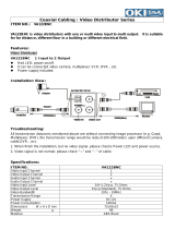
3 NAMES AND FUNCTIONS OF PARTS
Front panel
1. [STILL] button
Pauses the screen image when pressed during playback.
Pressing the button again restarts playback.
2. [PLAY/STOP] button and indicator
Plays back the normal image (indicator lights). When
pressed during playback, stops playback.
3. [REC/STOP] button and indicator
Starts normal recording. Indicator lights during recording.
During recording, pressing the button for at least 2
seconds stops recording and turns off the indicator.
4. [COPY] button (JP. 36)
Copies images to the hard disk’s archive area, to a
CompactFlash card, or to a Microdrive.
5. Removable HDD tray
6. HDD indicator
Lights up to indicate that data transfer between the unit
and HDD is enabled.
7. Tray release key
Turns power supply to the HDD ON and OFF. When the
key is turned clockwise, the HDD indicator will light up
indicating the ON condition. When OFF, the tray can be
removed. See caution for the key operation. (JP. 11)
8. HDD access indicator
Lights up to indicate the reading or writing of data.
9. [CHANGE DISK] button and indicator (JP. 18)
The red indicator lights when the power is turned ON.
When this button is held down for 2 seconds, the green
indicator flashes then lights, and the HDD can be
removed. If an HDD or fan error occurs, the red indicator
flashes.
10. [TIMER] button (JP. 23)
When pressed while recording is stopped, the unit enters
timer record standby. When the set time arrives, the digital
video recorder starts timer recording.
11. [ALARM] button (JP. 30)
When the [ ] or [ ] button is pressed during
playback, the unit skips to the next earlier or later alarm.
12. [SEARCH] button (
JP. 29)
z When the button is pressed while recording or stopped,
the search setting screen is displayed.
z When the button is pressed during the playback of
frame-recorded images, the playback mode is toggled
between Frame and Field.
13. [MENU] button
Used to display the menu screens.
[CHANNEL] button (JP. 28)
When a multiplexer capable of decoding channel
information (i.e., camera numbers) is connected to the
unit, a channel can be specified for single-channel
playback using this button.
14. [MENU RESET] button (JP. 43)
Used to initialize the currently displayed sub-menu
settings.
In addition, this button can also be pressed while the
normal screen is displayed to make time adjustments.
15. [REVIEW/CLEAR] button (JP. 26)
When pressed during playback, lets you fast-rewind the
image while watching it on-screen. When pressed while
the image is still, reverse playback is performed. Also used
for menu screen operations.
16. [ ] button
Used to move the cursor in menu screens down. Also used
to change setting values.
Used for frame advance (reverse) and adjusting the CUE/
REVIEW speed. Also used to set the security lock.
12 659
11 13 14 20 21 22191712
181516 23 24
3
78
10
4
e00_l8had_us_7.book Page 13 Wednesday, March 10, 2004 2:47 PM

NAMES AND FUNCTIONS OF PARTS3
14 English
INTRODUCTION
17. [ ] button
Used to move the cursor in menu screens up. Also used to
change setting values.
Used for frame advance (forward) and adjusting the CUE/
REVIEW speed.
18. [CUE/ENTER] button
When pressed during playback, lets you fast-forward the
image while watching it on-screen. When pressed while
the image is still, forward playback is performed. Also used
for menu screen operations.
19. [EXIT/OSD] button (JP. 20)
z Returns the display to the normal screen when the main
menu, a sub-menu, or a setting screen is displayed.
z If pressed repeatedly during recording or playback, the
operation display can be moved or hidden.
20. TIMER indicator (JP. 23)
The indicator lights when the unit enters timer record
standby.
21. FULL indicator (JP. 23)
The indicator begins to flash when the remaining available
memory in the hard disk’s normal recording area reaches
the setting value.
When the recording area becomes full, this indicator turns
on and recording will be stopped.
22. ALARM FULL indicator (JP. 57)
The indicator begins to flash when the remaining available
memory in the hard disk’s alarm recording area reaches
the setting value.
When the recording area becomes full, this indicator turns
on and recording will be stopped.
23. ALARM indicator
Flashes when recording an alarm image. Indicator lights
during pre-alarm recording.
24. CompactFlash card slot (
JP. 38)
Used to insert a CompactFlash card or Microdrive.
e00_l8had_us_7.book Page 14 Wednesday, March 10, 2004 2:47 PM

NAMES AND FUNCTIONS OF PARTS3
English 15
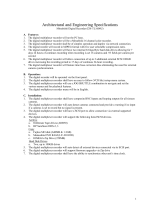
Rear panel
1. Fan
2. RS-232C terminal (when option board is installed)
3. RS-485 terminal A (when option board is installed)
4. RS-485 terminal B (when option board is installed)
z Do not connect the RS-485 A and RS-485 B connectors
to a phone line.
5. RS-485 termination switch (when option board is
installed)
6. LAN terminal (when option board is installed)
7. LAN link indicator (when option board is installed)
8. Power cord holder
Secure the power cord to the holder using the cord tie
(accessory) as shown in the illustration.
9. AC power socket (AC IN)
10. Wired remote control terminal
11. AUDIO IN terminal
12. AUDIO OUT terminal
13. VIDEO IN terminal
14. VIDEO LOOP OUT terminal
15. VIDEO OUT terminal
16. Control and alarm terminals
17. ALL RESET switch
Resets the recorder’s microcomputer. Menu settings are
not reset.
Resets the clock and backup mode setting.
ALL
RESET
LAN
OUT
LOOP OUT
VIDEO
NON-REC
COM IN
RESET
OUT OUT OUT OUT OUTOUT FULL FULLCOM COM COMIN IN
CLOCK
WARNING ALARM SERIES
SW
DC IN
REMOTE
IN
OUTIN
OFF ON
RS485
TERMINATE
RS485
RS232C
BA
AUDIO
ALARM
12 63
11 13 1412 15 16
7
10
45
98
17
Power cord tie
Pin Signal
COM Ground
ALARM IN Alarm input
ALARM RESET IN Alarm reset input
ALARM OUT Alarm output
NON REC OUT Non rec out terminal
COM Ground
CLOCK IN Clock adjust input
CLOCK OUT Clock adjust output
WARNING OUT Warning out terminal
DISK FULL OUT HDD space warning output
ALARM FULL
OUT
Alarm-recording area space warning output
COM Ground
SERIES IN
Input terminal used when recording with
multiple digital video recorders connected.
SERIES OUT
Output terminal used when recording with
multiple digital video recorders connected.
SWITCH OUT Switch output
COM Ground
NON-REC
COM IN
RESET
OUT OUT OUT OUT OUTOUT FULL FULLCOM COM COMIN IN
CLOCK
WARNING ALARM SERIES
SW
ALARM
e05_l8had_us_7.fm Page 15 Friday, March 12, 2004 9:46 AM

16 English
INTRODUCTION
4 INSTALLATION AND CONNECTIONS
This section describes how to connect the digital video recorder to the CCTV camera and other devices. Be sure to read the
instruction manuals for each connected device. Improper connections can cause smoke or malfunctions.
The connections for the camera, TV monitor, system controller, multiplexer, microphone, and PC are shown below.
The connections for a remote control circuit are shown
below. Making the connections shown below lets you
operate the digital video recorder by remote control.
z Connect the cable of the wired remote control (VA-
RMN01, sold separately) to the wired remote control
terminal.
The DSR-300 will function as follows in response to VA-
RMN01 key operations.
(1) Insert the cable while pushing in the lock pin using a
flat-blade screwdriver.
(2) Remove the screwdriver to secure the cable in place.
Basic connections
ALL
RESET
LAN
OUT
LOOP OUT
ALARM NON-REC
COM IN
RESET
OUT OUT OUT OUT OUTOUT FULL FULLCOM COM COMIN IN
CLOCK
WARNING ALARM SERIES
SW
DC IN
REMOTE
IN
OUTIN
OFF ON
RS485
TERMINATE
RS485
RS232C
BA
AUDIO
VIDEO
Microphone
(sold separately)
Amp (sold separately)
CCTV camera
(sold separately)
Video
input terminal
To audio input
terminal
Multiplexer (sold separately)
* When controlling the multiplexer from a system controller
System controller (sold separately)
Switching HUB
* Wrap the ferrite core once
around the LAN connection
cable before attaching the
cable. (Packaged together
with the option RS-485/
232C/LAN interface board.)
*
PC
PC
Connecting a remote control circuit
VA-RMN01 key DVR operation
REC REC
MENU MENU
↓ SHIFT/SHIFT → TIMER/SEARCH
↓ REC/PLAY SPEED ↑↓ / ↑
VA-RMN01
REW/REVIEW REW/REVIEW
PLAY PLAY
FF/CUE FF/CUE
REVERSE EXIT/OSD
STOP STOP
PAUSE/STILL PAUSE/STILL
Connecting cables to the control and
alarm terminals
VA-RMN01 key DVR operation
Cable
Flat-blade screwdriver
e00_l8had_us_7.book Page 16 Wednesday, March 10, 2004 2:47 PM

INSTALLATION AND CONNECTIONS4
English 17
Connecting a multiplexer
Making analog series connections
ALL
RESET
LAN
OUT
LOOP OUT
ALARM NON-REC
COM IN
RESET
OUT OUT OUT OUT OUTOUT FULL FULLCOM COM COMIN IN
CLOCK
WARNING ALARM SERIES
SW
DC IN
REMOTE
IN
OUTIN
OFF ON
RS485
TERMINATE
RS485
RS232C
BA
VIDEO
AUDIO
Multiplexer (sold separately)
Ground (C)
Alarm input
terminal
Alarm output terminal
Analog
input
Analog
output
Switch input terminal
Switch output terminal
Monitor (sold separately)
ALL
RESET
LAN
OUT
LOOP OUT
ALARM NON-REC
COM IN
RESET
OUT OUT OUT OUT OUTOUT FULL FULLCOM COM COMIN IN
CLOCK
WARNING ALARM SERIES
SW
DC IN
REMOTE
IN
OUTIN
OFF ON
RS485
TERMINATE
RS485
RS232C
BA
ALL
RESET
LAN
OUT
LOOP OUT
ALARM NON-REC
COM IN
RESET
OUT OUT OUT OUT OUTOUT FULL FULLCOM COM COMIN IN
CLOCK
WARNING ALARM SERIES
SW
DC IN
REMOTE
IN
OUTIN
OFF ON
RS485
TERMINATE
RS485
RS232C
BA
VIDEO
AUDIO
VIDEO
To 3rd
and sub-
sequent
DVRs
CCTV camera
(sold separately)
Amp (sold separately)
Amp (sold separately)
Monitor (sold separately) Monitor (sold separately)
To Series out
To Common
To Series in
To Series inTo Series out
To Common To Common
To Series in To Series out
e00_l8had_us_7.book Page 17 Wednesday, March 10, 2004 2:47 PM

INSTALLATION AND CONNECTIONS4
18 English
INTRODUCTION
1 When you have finished making all the
other connections, insert the power
plug into the wall outlet.
There is no power switch. The display indicators flash, and
after a few moments, the monitor screen displays the
camera image.
z When turning the power ON for the first time
“PLEASE SET THE CLOCK” is displayed on the
monitor screen. Follow the procedures on P. 22 to set
the clock.
z If the clock is already set
The operation display area is displayed.
z If the CHANGE DISK indicator is flashing in red
The digital video recorder has a self-check function that
indicates problems. If there is a problem at power ON or
during operation, the type of problem is indicated by
how rapidly the CHANGE DISK indicator flashes.
Contact a Sanyo Authorized Service Centre if the
CHANGE DISK indicator flashes.
4 flashes per second:
The hard disk is checked automatically at power ON.
If a hard disk problem is found, the CHANGE DISK
indicator flashes, and the hard disk must be replaced
or reformatted. If you need to save images stored on
the disk, contact a Sanyo Authorized Service Centre.
1 flash per second:
Fan problem
z If you disconnect the power cable
Do not move the recorder or subject it to vibration for at
least 30 seconds after turning OFF the power.
The disk in the hard disk drive briefly keeps spinning
after power OFF due to inertia, during which time the
head is unstable. At this time, the disk is sensitive to
shocks or vibrations, so avoid even light shocks.
Connecting the power cord
* Attach the supplied ferrite core to the base of the
power cable (coiling not necessary).
*
Operation
display area
01- 01- 04
00: 00: 00 EN 10FPS
e00_l8had_us_7.book Page 18 Wednesday, March 10, 2004 2:47 PM

English 19
1 PREPARING FOR USE
Whenever the power is turned ON, the operation display
area will be displayed at the top left of the monitor screen.
This area indicates the date and time, the image quality,
the recording rate, and other information needed for
operation.
(1) Camera number display (JP. 28)
Displayed when a camera number has been specified for
playback.
(Only in cases where a multiplexer capable of decoding
channel information is connected to the unit.) (JP. 52)
(2) Date display (JP. 22)
Shows the month/day/year.
01-01-04 (month-day-year)
(3) Operating symbol display
Displays the current operation (such as recording or
playback).
: Recording : Fast-forward playback
: Playback : Fast-rewind playback
: Reverse playback : Slow playback
: Still : Reverse slow playback
z During simultaneous recording and playback, the
display indicates playback ( ).
(4) Remaining memory in recording area (JP. 57)
Displays the remaining memory as a percentage when
overwriting in the normal recording area or the alarm
recording area is forbidden. To change the remaining-
memory display format, follow the instructions in “4.
RECORDING CONDITIONS SET” from the menu.
(5) Alarm display and alarm count display (JP. 24)
When you set an alarm using the “ALARM REC MODE
SET” menu item, the alarm display area displays the
following information.
z When alarm recording is set;
“ALARM” is displayed.
“ALARM” is flashed during alarm recording.
z When pre-alarm recording is set;
“PRE” is displayed.
When an alarm occurs, “PRE” disappears, “ALARM” is
displayed, and the number of alarms is shown. The total
number is indicated in the alarm display.
z When performing playback from the archive area;
“ARCHIV” is displayed.
(6) Time display (JP. 22)
“00:00:00” is displayed when you turn the power ON for
the first time. The digital video recorder uses the date and
time to manage recording and playback points.
(7) Image quality display (JP. 59)
Displays the quality of the image that can be recorded on
the hard disk. Set to “EN” (Enhanced) in the default
settings.
(8) Recording rate display (JP. 46)
Displays the recording rate that can be recorded on the
hard disk. The default setting is 10.00 FPS (for field
recording).
z Although operations such as playback, copying, and
data transfer are possible while recording, this unit
gives priority to recording and other operations may be
delayed as a result. Communication may be cut off in
some cases.
Operation display area
z
01- 01- 04 ALARM 0001
00: 00: 00 EN 10FPS
(1) (2)
(6) (7)
(3) (4) (5)
(8)
CH 4
z
100
%
05-10-04 ALARM 0001
10:50:00 EN 10FPS
Setting Description
SF Super Fine
FI Fine
EN Enhanced
NO Normal
BA Basic
e00_l8had_us_7.book Page 19 Wednesday, March 10, 2004 2:47 PM
Page is loading ...
Page is loading ...
Page is loading ...
Page is loading ...
Page is loading ...
Page is loading ...
Page is loading ...
Page is loading ...
Page is loading ...
Page is loading ...
Page is loading ...
Page is loading ...
Page is loading ...
Page is loading ...
Page is loading ...
Page is loading ...
Page is loading ...
Page is loading ...
Page is loading ...
Page is loading ...
Page is loading ...
Page is loading ...
Page is loading ...
Page is loading ...
Page is loading ...
Page is loading ...
Page is loading ...
Page is loading ...
Page is loading ...
Page is loading ...
Page is loading ...
Page is loading ...
Page is loading ...
Page is loading ...
Page is loading ...
Page is loading ...
Page is loading ...
Page is loading ...
Page is loading ...
Page is loading ...
Page is loading ...
Page is loading ...
Page is loading ...
Page is loading ...
Page is loading ...
Page is loading ...
Page is loading ...
Page is loading ...
Page is loading ...
Page is loading ...
Page is loading ...
Page is loading ...
Page is loading ...
Page is loading ...
Page is loading ...
Page is loading ...
Page is loading ...
Page is loading ...
Page is loading ...
Page is loading ...
Page is loading ...
Page is loading ...
Page is loading ...
Page is loading ...
Page is loading ...
Page is loading ...
Page is loading ...
Page is loading ...
Page is loading ...
Page is loading ...
Page is loading ...
Page is loading ...
Page is loading ...
Page is loading ...
Page is loading ...
Page is loading ...
Page is loading ...
Page is loading ...
Page is loading ...
Page is loading ...
Page is loading ...
Page is loading ...
Page is loading ...
Page is loading ...
Page is loading ...
Page is loading ...
Page is loading ...
Page is loading ...
Page is loading ...
Page is loading ...
Page is loading ...
Page is loading ...
Page is loading ...
Page is loading ...
Page is loading ...
Page is loading ...
Page is loading ...
Page is loading ...
Page is loading ...
Page is loading ...
Page is loading ...
Page is loading ...
Page is loading ...
Page is loading ...
Page is loading ...
Page is loading ...
Page is loading ...
Page is loading ...
Page is loading ...
Page is loading ...
Page is loading ...
Page is loading ...
Page is loading ...
Page is loading ...
Page is loading ...
Page is loading ...
/