Page is loading ...

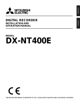
INSTALLATION &
OPERATION MANUAL
Digital Video Recorder
MV-DR3000
Before trying to connect or operate this product, please read this manual completely

1
SAFETY PRECAUTIONS
All the following safety and operated instructions which will prevent harm or damage to the operator and
other persons should be read before the unit is operated.
INFORMATION
This equipment has been tested and found to comply with the limits for a Class A digital device,
pursuant to Part 15 of the FCC Rules. These limits are designed to provide reasonable protection
against harmful interference when the equipment is operated in a commercial environment. This
equipment generates, uses, and can radiate radio frequency energy and, if not installed and used
in accordance with the instruction manual, may cause harmful interference with radio
communications.
Operation of this equipment in a residential area is likely to cause harmful interference in which
case the user will be required to correct the interference at his own expense.
WARNING
!
To reduce the risk of fire or electric shock, do not expose this appliance to rain or moisture.
!
Do not block ventilation openings.
!
Do not place anything on top of the unit that might spill or fall into it.
!
Do not attempt to service this unit yourself as opening or removing covers may expose you
to dangerous voltage or other hazards. Please refer all servicing to qualified service
personnel.
!
Do not use liquid cleaners or aerosols for cleaning.
!
This installation should be by a qualified service person and should conform to all local
codes.
To prevent fire or electric shock, do not overload wall outlets or extension cords.
This unit must be grounded to reduce the risk of electric shock hazard.
CAUTION
!
Danger of explosion if battery( RTC Battery ) is incorrectly replaced. Replace only with the
same or equivalent type recommended by the manufacturer. Dispose of used batteries
according to the manufacturer’s instructions.
!
Risk of explosion if replaced by an incorrect type. Dispose of used batteries according to
the instructions.

2
1. INTRODUCTION ................................. 4
1.1 Product Introduction................................4
1.2 Product Features ....................................4
1.3. FRONT / REAR VIEW............................5
1.3.1 Front View .............................................5
1.3.2 Rear View..............................................8
1.4 ALARM In / Out .......................................9
2. INSTALLATION ................................. 10
2.1 Basic Connection ..................................10
2.2 Hard-disk Drive Installation ...................11
2.3 System Information ...............................12
2.4 Updating System Software....................13
3. OPERATIONS ................................... 14
3.1 Configuring Recording Settings ............14
3.2 Recording Operations ...........................17
3.2.1 Manual Recording...............................17
3.2.2 Timer Recording..................................17
3.2.3 Alarm / Motion Recording....................18
3.2.4 Externally Triggered Recording ..........18
3.3 Playback Operations.............................20
3.3.1 Normal Playback.................................20
3.3.2 Fast Forward/Backward ......................20
3.3.3 Slow Forward/Reverse........................21
3.3.4 Play back Picture-by-picture ...............21
3.3.5 Playback Recorded Video from an HDD
of the mobile rack (for removable HDD
model only) ..............................................21
3.3.6 Picture in Picture ( PinP ) Display Mode
.................................................................21
3.4 Search Operations ................................22
3.4.1 FULL LIST Search ..............................22
3.4.2 ALARM LIST Search...........................22
3.4.3 TIME Search .......................................23
3.4.4 THUMBNAIL Search ...........................23
3.4.5 SD CARD Search ...............................24
3.4.6 CD Menu (For CD-RW model only) ....25
3.5 Backup Operations ...............................26
3.5.1 CD Rewritable unit Backup Operations
(FOR CD-ROM MODEL ONLY)...............26
3.5.2 Mobile Rack HD Backup Operations
(FOR REMOVABLE HDD MODEL ONLY)
................................................................ 27
3.5.3 SD Card Backup Operations for
Removable HDD Model .......................... 28
3.5.4 Backup the System setting info into an
SD card. .................................................. 29
3.5.5 Updating System Software................. 30
3.6 Key Lock Operation.............................. 30
4. MENU SETUP....................................31
4.1 REC Setting ......................................... 31
4.2 ALARM / MOTION Setting ................... 32
4.3 CLOCK / TIMER Setting ...................... 34
4.4 COMMUNICATION Setting .................. 35
4.5 DISK Setting......................................... 37
4.6 SYSTEM Setting .................................. 39
5. NETWORK.........................................41
5.1 Network Configuration.......................... 41
5.1.1 Cable Connections............................. 41
5.1.2 Configure Your DVR Network Settings
................................................................ 42
5.1.3 TCP/IP Communication Setup ........... 44
5.1.4 Testing Connection............................. 46
5.2 TRIPLEX 1 CH DVR VIEWER
SOFTWARE: Introduction ............................ 47
5.2.1 Software installation ........................... 47
5.2.2 Short introduction ............................... 48
5.2.3 Operation............................................ 49
5.3 Microsoft Internet Explorer ................... 55
5.3.1 Connecting the DVR .......................... 55
5.3.2 Change Record / Alarm Setting ......... 56
5.3.3 Change Timer Record Setting............ 56
5.3.4 Pan / Tilt / Zoom Setting..................... 57
6. TEXT INSERTION FUNCTION ..........58
7. MISCELLANEOUS ............................ 73
7.1 RS-232 & RS-485 Setup & Protocol .... 73
7.1.1 RS232 & RS485 Setup ...................... 73
7.1.2 Communication Protocol .................... 73
7.2 Hard Disk Installation ........................... 77
7.2.1 Built-in hard disk................................. 77
CONTENTS

3
7.2.2 Mobile Rack (FOR REMOVABLE HDD
MODEL)...................................................78
7.3 System Default......................................80
7.4 O.S.D Message.....................................81
7.5 Time Index Table ...................................82
7.6 Specifications ........................................83
7.7 Compatible Multiplexer Devices............84
7.8 ScanIP ..................................................85
APPENDIX 1. – Using CD Discs
(FOR CD-RW MODEL ONLY) ......... 87

4
1. INTRODUCTION
1.1 Product Introduction
This 1CH Triplex DVR is a storage media of
digital video image, which uses hard disk
drives instead of VCR tapes to store video. It
enables you to enjoy the extreme flexibility of
digital image archiving instead of clumsy tape
management, and is compatible with most
multiplexers in the market. Equipped with a
range of comprehensive features, such as
playback picture-by-picture, fast accessed
video recording by time and event, system
software which can be upgraded, the
expandable capacities of hard drive, and
much more, the DVR will make your
applications far more flexible and effective
than ever before. For all, the DVR is going to
prove the timely substitute for Time-lapse
VCR.
1.2 Product Features
z The full-capability triplex DVR allows
video recording while viewing live video
images and video playback images at the
same time.
z Stores video in hard-disk drives instead of
VCR tapes.
z Main recording media: one fixed
hard-disk drive and one removable
hard-disk (for removable model only).
z Main recording media: one fixed HDD
plus a CD-RW. (For CD-ROM model only)
z Hard-disk drive hot-swapping capability.
z Pre-alarm image recording.
z Capable of working with various known
multiplexers.
z Time-lapse and real-time recording.
z Refresh rate up to 60 IPS (50 IPS for
PAL).
z Image quality selectable at 4 different
levels for recording.
z Event/Timer/Alarm recording mode.
z Quick search by time, alarm, event, and
recording list.
z Fast and slow playback of recorded video
at various speeds.
z Single-picture playback.
z On-screen setup menu, title and system
timer.
z Password protection.
z Motion detection.
z Disk-full warning and operation status
LEDs.
z RS-232, RS-485 communication ports.
z Remote control via RS-232, RS-485 and
Ethernet ports.
z Power recovery on interruption.
z Operation-status record log.
z Distributes live and recorded images
through the TCP/IP network environment.
z Audio function included (
16 bits, 11 KHz /
22KHz).
z Built-in SD card slot for copying image to
SD card.
z Supports DHCP protocol.
1. INTRODUCTION

5
1.3. FRONT / REAR VIEW
1.3.1 Front View
FOR CD-ROM MODEL FOR REMOVABLE HDD MODEL
1
CD-RW device compartment:
The compartment allows you to burn the
data mostly for backup purposes. This tray
is for loading the CD disc. It will accept 120
mm and 80 mm discs. Please place the
discs in the exact center of the tray.
Writing Display Light:
When a disc is being burnt, the display
light will be a red flash.
Power Supply / Reading Light:
When a disc has been ejected, the display
light will be green. When a disc is unable to
be read, or the device is being repaired,
the display light will flash.
1
Hard-disk drive compartment:
The compartment allows you to install a
hard disk drive mostly for backup
purposes. Make sure the drive is well
secured with the mounting screws in the
mobile rack before you put the rack into
the compartment. And remember to turn
on the power of the compartment by
locking it.
2
Hard-disk compartment lock:
The key lock secures a hard disk in
place. Unlock the compartment before
you remove the hard disk from the slot
without turning off the device.
INTRODUCTION ( continued )
Power Monitor Display Search Setup Enter Play Pause Stop Rec
SD Card
DISK A-rec T-rec
FFREW
1
7 8 9 4 3 5 6
24 2a 2b 23
16 10 15 13 12 11 14
19 18 17
20
21
22
Power Monitor Display Search Setup Enter Play Pause Stop Rec
SD Card
DISK A-rec T-rec
FFREW
7 8 9 4 3 5 616 10 15 13 12 11 14
1
2
19
23 24
18 17
20
21
22

6
3
PAUSE button:
In a playback display, press this to freeze the display. During the freeze, press to display one
frame/field of a picture at a time in the forward direction. (A green light is on the PAUSE mode.)
4
PLAY button:
Press to play back a recorded video from the hard disk. (A green light shows in the PLAY mode.)
5
STOP button:
Press to stop playing back a recorded video. (A green light goes on in the STOP mode.)
6
REC button:
Push to start recording video into a hard disk while in the live display mode. (A red light turns on
in the REC mode.)
7
POWER button:
Press this button for at least 3 seconds to power off. Press again to activate the device.
8
DISPLAY button:
Press to show the system operation status on the screen.
9
Setup button:
Press this to enter the setup menu. Press again to exit the setup mode.
10
Search button:
Press to enter the search mode to access the recorded video.
11 14
Left / Right buttons:
Press the two buttons to highlight desired items in the menu setup mode. For the Key Lock
operation, press these two buttons simultaneously once; to disable Key Lock, press these two
buttons again simultaneously.
12 13
Up / Down buttons:
Press these two buttons to select the desired contents for programming in the setup menu mode.
15
Enter Button:
Press to enter a selected item and save the setting in the menu setup mode.
16
Monitor button:
Press to switch between a multiplexer-decoded video and the encoded video to be displayed
when connected with a multiplexer. When the button light is on it indicates the unit is displaying
the decoded video.( The images are not multiplexing . ) In this mode, the unit doesn’t display the
OSD message of the unit on the screen. However, this doesn’t affect the unit’s OSD message,
which is recorded into hard-disk drives. When the button light is off it indicates the unit is
displaying encoded video. (The images switch swiftly).
17
T-rec Indicator:
This indicator of the timer recording mode lights up to signal the scheduled record setting is on.
18
A-rec Indicator:
This indicator of the alarm-recording mode lights up to indicate the alarm record setting is on.
19
DISK Indicator:
The indicator shows the operation status of the unit’s hard-disk drives. The green light indicates
the hard-disk drive is storing or retrieving data. The red light signals the hard-disk drive is filling up.

7
The orange light indicates the hard-disk is retrieving a disk-full status.
20
Shuttle Ring:
The shuttle can be moved forward and backward for playback in either direction. Turn this left to
play a recorded video in the reverse direction at faster or slower speeds than the recorded speed.
Turn this right to play a recorded video in the forward direction at faster or slower speeds than the
recorded speed.
21
Jog Dial:
This dial can act in both a forward and a backward direction, as well as step by step. Turn this left
to play a recorded video in the reverse direction. Turn this right to play a recorded video in the
forward direction.
22
SD CARD Slot:
This is used for system software updating and archiving/accessing critical images.
23
Eject button
Pressing this controls the insertion and
ejection of the tray.
24
Emergency Eject Button:
When the power supply has been
interrupted, or it is impossible to eject a
disc, please use a pin to press the
emergency eject button so that the
caddy will eject the disc.
23
Mobile Rack Power LED:
Indicates the power status of the Mobile
Rack. The green light indicates the
Mobile Rack is activating.
24
Mobile Rack HDD LED:
Indicates the HDD status of the Mobile
Rack. The orange light indicates the
HDD is storing or retrieving data.

8
1.3.2 Rear View
RS-232
ALARM
DC12V
RS-485
AUDIO
IN
IN
OUT
OUT
VIDEO
TO
MONITOR
TO
MUX'S VCR IN
FROM MUX
MAIN MONITOR
ETHERNET
10/100
I/O
25 26 27 28 29 31
32 33
34 35 37 38 36
25
VIDEO IN Connector: This BNC connector is
used to connect the video output from a
camera or a MUX to the DVR.
26
FROM MUX MAIN MONITOR Connector:
This BNC connector is used to connect the
live video output from a MUX to the DVR.
27
AUDIO IN Connector: This connector is used
to connect the audio output from a camera, a
MUX or other devices to the DVR.
28
ETHERNET 10/100 Connector: This is a
standard RJ-45 connector for 10/100 Mbps
Ethernet networks.
29
RS-485 Port: The RS-485 communication
ports function as connectors when two or
more units are serially connected to an
external control device.
31
RS-232 Port: The RS-232 communication
port functions as a connector to an external
control device. Please refer to 6.1 RS-232 &
RS-485 Protocol for more details.
32
VIDEO OUT Connector: The connector
provides the unit’s composite video signals to
a MUX.
33
MONITOR Connector: The connector
provides the unit’s composite video or a
MUX’s live signal if connected to a display
device.
34
AUDIO OUT: This provides the unit’s audio
signal to a speaker.
35
ALARM I/O: This is a 9-PIN D-SUB
connector including SWITCH OUT, GROUND,
ALARM OUT, DISK FULL, RECORD IN,
ALARM RESET, and ALARM IN points for
connecting with external devices. Please refer
to the next section for details.
36
Plug Inlet: The inlet connects to an external
power supply. Connect the 12 V DC UL-listed
Class 2 Power Supply.
37
Wire Catch: The wire catch secures the
power cord and keeps it in place (so that it
does not droop or hang loosely).
38
Ground Screw’s: The ground screw is for a
chassis terminal.

9
ALARM IN
ALARM OUT
RECORD IN GROUND
DISK FULL
ALARM RESET
NO CONNECTION NO CONNECTION
SWITCH OUT
12345
6789
1.4 ALARM In / Out
The above figure is a rear view.
1. GND: Ground Contact.
2. ALARM OUT (OUTPUT): This is an
alarm-output trigger. Connect this to
external devices such as buzzers or
lights.
5V
0V(Active)
3. DISK FULL (OUTPUT): This is a disk-full
output trigger. Connect this to external
devices such as buzzers or lights.
5V
0V(Active)
4. ALARM RESET (INPUT): This pin
connects to an alarm-clear device for
clearing an alarm.
5V
0V(Active)
5. RECORD IN (INPUT): This pin connects
to a record-triggering device for starting a
record.
5V
0V(Active)
6. SWITCH OUT (OUTPUT): This pin,
sending out timing signals (falling /
negative) to a multiplexer, connects to a
multiplexer’s trigger terminal so the
multiplexer can switch to using the same
recording speed as the DVR.
7. NO CONNECTION
8. NO CONNECTION
9. ALARM IN (INPUT): This is an alarm input,
which can be programmed in the menu
system to Normally Open or Normally
Closed.
5V
0V(Active)

10
2. INSTALLATION
2.1 Basic Connection
A
. Connecting with a Single Camera
Please set the MULTIPLEXER option to OFF on
the REC SETTING page in the setup menu
when it is connected with a single camera.
(Please refer to section 4.1 MULTIPLEXER.)
B. Connecting with a Multiplexer
To match the multiplexer’s recording speed,
please set the MULTIPLEXER option to ON on
the REC SETTING page in the setup menu
when it is connected with a multiplexer. (Please
refer to section 4.1 MULTIPLEXER.)
C. Connecting with a Quad
Please set the MULTIPLEXER option to OFF on
the REC SETTING page in the setup menu
when it is connected with a quad. (Please refer
to section 4.1 MULTIPLEXER.)
2. INSTALLATION
RS-232
ALARM
DC12V
AUDIO
IN
IN
OUT
OUT
VIDEO
TO
MONITOR
TO
MUX'S VCR IN
FROM MUX
MAIN MONITOR
I/O
Camera
Monitor
RS-485
ETHERNET
10/100
12345
6789
SD Card
RS-232
ALARM
DC12V
AUDIO
IN
IN
OUT
OUT
VIDEO
TO
MONITOR
TO
MUX'S VCR IN
FROM MUX
MAIN MONITOR
I/O
Audio
IN
OUT
S-video
Trig In
Multiplexer
GROUND
SWITCH OUT
PC
RS-485
ETHERNET
10/100
Monitor
Video in
Audio in
SD Card
RS-232
ALARM
DC12V
AUDIO
IN
IN
OUT
OUT
VIDEO
TO
MONITOR
TO
MUX'S VCR IN
FROM MUX
MAIN MONITOR
I/O
Audio
IN
OUT
S-video
Quad
Monitor
Video in
Audio in
PC
RS-485
ETHERNET
10/100

11
D. Attaching an
External Device to DVR
Connect an alarm out, alarm input, and a peripheral device as shown in the diagram below.
2.2 Hard-disk Drive Installation
The DVR is equipped with two compartments
of hard disk drive (for removable model
only), The unit usually comes with one
hard-disk drive installed in the compartment
HD1, which is default- configured as a master.
If you need a second hard-disk drive to be
installed in the compartment HD2 (Mobile),
please contact your distributors or installers
for specific instructions on how to install it.
Please don’t serve yourself before consulting
your installers. If there is only one hard-disk
drive in the mobile compartment, please set
the HD2 USAGE option to REC (please refer
to section 4.5) before proceeding with the
recording function. The jumper-settings
arrangement of installed hard-disk drives for
the system (Table 3.2 A.) is shown in the
tables below.
Note: The CD-RW model is equipped with a
fixed hard- disk and a CD-RW drive. The unit
usually comes with one hard-disk drive
installed in the compartment HD1, which is
default-configured as a master.
Table 3.2 A. The jumper settings of hard-disk drives in the system
Location Jumper
IDE 1 Compartment HD 1 Master (Default)
IDE 2 Compartment HD 2 Master
INSTALLATION ( continued )
RS-232
ALARM
DC12V
AUDIO
IN
IN
OUT
OUT
VIDEO
TO
MONITOR
TO
MUX'S VCR IN
FROM MUX
MAIN MONITOR
I/O
12345
6789
Alarm Reset
(Normally Open)
(Normally Open)
Alarm in
Ground
RS-485
ETHERNET
10/100
Lamp

12
Table 3.2 B. Compatible hard-disk drives
Manufacturer Model Capacity Rotation
ST340810A 40G 5400 RPM
ST380020A 80G 5400 RPM
ST320014A 20G 5400 RPM
ST340015A 40G 5400 RPM
ST380012ACE 80G 5400 RPM
ST3120025ACE 120G 5400 RPM
ST340014A 40G 7200 RPM
ST380011A 80G 7200 RPM
ST380013A 80G 7200 RPM
ST3120026A 120G 7200 RPM
ST3160023A 160G 7200 RPM
ST3200822A 200G 7200 RPM
ST3250823A 250G 7200 RPM
Seagate
ST3400832A 400G 7200 RPM
4A160J0-1A 160G 5400 RPM
4R080L0-1 80G 5400 RPM
5A300J0-1A 300G 5400 RPM
6Y080L0 80G 7200 RPM
6Y080L0-3 80G 7200 RPM
6Y120L0-1 120G 7200 RPM
6Y200P0-1A 200G 7200 RPM
6Y250P0-1A 250G 7200 RPM
6B300R0 300G 7200 RPM
6L080P0 (RoHS) 80G 7200 RPM
6L100P0 (RoHS) 100G 7200 RPM
6L120P0 (RoHS) 120G 7200 RPM
6L160P0 (RoHS) 160G 7200 RPM
6L200P0 (RoHS) 200G 7200 RPM
6L250R0 (RoHS) 250G 7200 RPM
Maxtor
6L300R0 (RoHS) 300G 7200 RPM
WD800AB 80G 5400 RPM
WD1200AB 120G 5400 RPM
WD800BB 80G 7200 RPM
WD1200BB 120G 7200 RPM
WD1800BB 180G 7200 RPM
WD2000BB 200G 7200 RPM
Western Digital
WD2500JB 250G 7200 RPM
SV0802N 80G 5400 RPM
Samsung
SV1203N 120G 5400 RPM
NOTE: Hard-disk drives not shown on this list have not been tested by our engineering team
and are not recommended for use with this product. For the latest updated list on the
recommended hard disk drives, please contact your dealers or distributors.
2.3 System Information
You can display system settings information as
shown on Table 3.3 A below at any time by
pressing the Display button
8
. In the
playback mode, the recorded video information
is displayed. In the live or recording mode, the
Manual Recording information is displayed.
However, when the DVR is displaying a
decoded image from a multiplexer, you must
first switch the unit to encoded image
displaying (the pictures is switching swiftly and
the light of the Monitor button
16
is off) by
pressing the Monitor button
16
. Each
sequential press of the Display button
8
displays a different message detailed in the
following example. By default, the unit displays
the time, date, and an indicating bar of capacity
status on a monitor as shown.
Default Display
( Capacity Used ) ( Capacity Remaining )
09- 05-2003 16:13:02
(Date) (Time)

13
Press the Display button
8
once; the DVR
will display the following sample message plus
the default display. Press the Display button
8
again; the unit will not display any OSD
message. Press the button one more time to
go back to the default display.
Total capacity of installed hard disk: 59 GB.
(12.4 HR): Total 12.4 hour recording time available.
( ): Timer record activated.
(
): Alarm record activated.
(
): motion detection activated.
(QUALITY: BEST): Record quality setting: BEST.
(NTSC ): NTSC system.
(RATE: 6 HR): Setting of Record time mode: 6 hours.
(20 F/S): Record speed setting: 20 fields/sec.
(MUX: OFF): Only connected to a single camera.
( ): Audio function activated.
(
): Indicates which HDD is activated.
( 9K ): The image file size
.
( HD ): Hard-disk compartment.(HD2 IS FOR
REMOVABLE MODEL ONLY)
(CD):CD-RW Compartment. (FOR CD-RW MODEL
ONLY)
( SIZE 20G): The capacity of the installed hard disk.
( REC ): Percentage of system Recording.
( PLAY ): Percentage of system Playback.
( IP : 192 . 168 . 1 . 90 ): Network IP Address
192.168.1.90
(
): External signal.
( x ): Cannot operate now.
2.4 Updating System Software
Please take the following steps to safely update it.
1. Inserting your SD card into your SD card
reader.
2. Plug your card reader's USB connector into
your PC.
3. Save the firmware ( the multi.bin file ) into the
SD card.
4. After you have checked that the saving is
complete, take the SD card out of the card
reader.
5. Turn off the DVR.
6. Insert the SD card into the built-in SD slot of
the unit.
7. Hold down the the Up
12
and Down
13
buttons simultaneously, and then turn on the
DVR.
8. Keep holding down the buttons until the DVR
sounds a tone and display the message
“ XXXXXX BYTES READ” Now the DVR is
updating the system software, which will take
approximately 90 seconds to process.
9. Restart the unit when the device sounds a tone
twice and displays the message “PLEASE
RESTART” The process is complete.
(If you have already followed the procedure
1~9. the unit, however, not being able to power
on. Please first check if the SD card you are
using is functioning and the file is intact. And
then start procedures 1 ~ 9 all over again.)
10. Verify the version of the system software from
the “MAIN MENU -> SYSTEM -> VERSION” by
push down Setup button. (Please refer to
section 4.6 VERSION.)
!
Caution:
1. Before carrying out the updating procedures, please
ensure the SD card is working and the file of system
software is intact.
2. Don’t interrupt the process while the unit is updating
itself, as this will cause the unit to crash.
1+2 :59G 12.4 HR
QUALITY : BEST
NTSC
RATE :6HR
MUX :ON
20 F/S
9K
HD SIZE REC PLAY
1 20G 10.0% 0.1%
2 39G 0.0% 0.0%
(For removable HDD model only)
CD 133M 80.0% (For CD-RW model only)
IP : 192.168.1.90
14-04-2005 09:46:53
13 12

14
3. OPERATIONS
This section shows you how to operate and
manage the DVR when it gets in the way.
3.1 Configuring Recording
Settings
Recording time will vary depending on the
image size, recording rate, and the capacity of
the hard-disk drives. Generally, the DVR
comes with a built-in hard-disk drive for
continuous recording from one to four weeks
under most recording conditions. The table
below shows the possible recording times
based on a 20GB hard-disk drive at certain
refresh rates and the corresponding image
quality. With one or more hard-disk drives in
operation, please calculate the recording time
using the table below in accordance with your
requirement. For an NTSC unit, for example, if
the unit is set to record images with BEST
quality at a 60 fps record rate, normally a
20GB hard-disk drive will be filled in 3.7 hours
(see the gray area in the table). If the total
capacity of 80GB hard-disk drives is in use
under the same refresh rate and picture quality,
it will be filled in 14.8 hours (4 times the rate of
a 20GB hard-disk drive).
Note: Set up the REC Time Mode when a
multiplexer is connected.
If a multiplexer is connected, for optimum
image recording and playback, the record
speed of the multiplexer must be correctly
adjusted to match the DVR and set the
MULTIPLEXER option on the setup menu to
ON. This can be done by either of the two
methods detailed below.
(1) If an APPRO multiplexer is connected for use,
you can program the REC time mode of the
multiplexer by referring to the table below (each
refresh rate refers to one REC time mode).
(2) For a multiplexer other than APPRO, please
connect the SW. OUT terminal in the 9-PIN
D-SUB connector on the rear panel of the DVR
to the multiplexer’s trigger contact. The DVR will
provide the timing signal (Negative/Falling) to
the multiplexer. Thus, if the DVR changes the
recording speed, the multiplexer will
automatically adjust the record to match. A
2-hour and 4-hour timing signal in NTSC or a
3-hour and 6-hour one in PAL is constantly
negative / falling.
3. OPERATIONS

15
NTSC (MUX ON)
Audio ON (11KHz)
Possible Recording Time HDD=20GB ( hour )
BEST
3.5 4.4 6.6 11.0 23.6 N.A. N.A. N.A. N.A. N.A. N.A.
HIGH
3.5 5.5 8.3 13.7 29.2 N.A. N.A. N.A. N.A. N.A. N.A.
STANDARD
3.7 7.4 11.0 18.1 38.2 N.A. N.A. N.A. N.A. N.A. N.A.
Image
Quality
BASIC
5.5 11.0 16.4 26.7 55.3 N.A. N.A. N.A. N.A. N.A. N.A.
Refresh Rate (Field/Sec)
60 30 20 12 5.5 2.4 1.22 0.71 1/4 1/6 1/8
REC Time Mode
2 hr 4 hr 6 hr 12 hr 24 hr 48 hr 96 hr 168 hr 480 hr 720 hr 960 hr
NTSC (MUX ON)
Audio OFF
Possible Recording Time HDD=20GB ( hour )
BEST
3.6 4.5 6.7 11.3 24.8 56.5 110.7 192.1 544.7 816.0 1087.3
HIGH
3.6 5.6 8.4 14.1 31.0 70.6 138.4 240.1 680.9 1020.0 1359.1
STANDARD
3.7 7.5 11.3 18.8 41.1 94.1 184.6 320.2 907.9 1360.0 1812.2
Image
Quality
BASIC
5.6 11.3 16.9 28.2 62.1 141.2 276.9 480.3 1361.9 2040.1 2718.3
Refresh Rate (Field/Sec)
60 30 20 12 5.5 2.4 1.22 0.71 1/4 1/6 1/8
REC Time Mode
2 hr 4 hr 6 hr 12 hr 24 hr 48 hr 96 hr 168 hr 480 hr 720 hr 960 hr
NTSC (MUX OFF)
Audio ON (11KHz)
Possible Recording Time HDD=20GB ( hour )
BEST
3.5 4.4 8.8 13.2 25.7 N.A. N.A. N.A. N.A. N.A. N.A.
HIGH
3.5 5.5 11.0 16.4 31.7 N.A. N.A. N.A. N.A. N.A. N.A.
STANDARD
3.7 7.4 14.6 21.6 41.4 N.A. N.A. N.A. N.A. N.A. N.A.
Image
Quality
BASIC
5.5 11.0 21.6 31.7 59.7 N.A. N.A. N.A. N.A. N.A. N.A.
Refresh Rate (Field/Sec)
60 30 **20 **12 **5.5 2.4 1.22 0.71 1/4 1/6 1/8
REC Time Mode
2 hr 4 hr 6 hr 12 hr 24 hr 48 hr 96 hr 168 hr 480 hr 720 hr 960 hr
NTSC (MUX OFF)
Audio OFF
Possible Recording Time HDD=20GB ( hour )
BEST
3.6 4.5 9.0 13.5 27.1 58.7 113.0 194.4 547.0 818.3 1089.5
HIGH
3.6 5.6 11.3 16.9 33.9 73.4 141.2 243.0 683.8 1022.8 1361.9
STANDARD
3.7 7.5 15.0 22.6 45.2 97.9 188.3 324.0 911.7 1363.8 1815.9
Image
Quality
BASIC
5.6 11.3 22.6 33.9 67.8 146.9 282.5 486.0 1367.6 2045.7 2723.9
Refresh Rate (Field/Sec)
60 30 **20 **12 **5.5 2.4 1.22 0.71 1/4 1/6 1/8
REC Time Mode
2 hr 4 hr 6 hr 12 hr 24 hr 48 hr 96 hr 168 hr 480 hr 720 hr 960 hr
PAL (MUX ON)
Audio ON(11KHz)
Possible Recording Time HDD=20GB ( hour )
BEST
3.5 5.3 8.0 13.2 23.2 N.A. N.A. N.A. N.A. N.A. N.A.
HIGH
3.5 6.6 9.9 16.4 28.7 N.A. N.A. N.A. N.A. N.A. N.A.
STANDARD
4.4 8.8 13.2 21.6 37.6 N.A. N.A. N.A. N.A. N.A. N.A.
Image
Quality
BASIC
6.6 13.2 19.5 31.7 54.4 N.A. N.A. N.A. N.A. N.A. N.A.
Refresh Rate (Field/Sec)
50 25 17 10 5.5 2.9 1.52 0.88 1/4 1/6 1/8
REC Time Mode
3 hr 6 hr 9 hr 12 hr 24 hr 48 hr 96 hr 168 hr 480 hr 720 hr 960 hr
OPERATIONS ( continued )

16
PAL (MUX ON)
Audio OFF
Possible Recording Time HDD=20GB ( hour )
BEST
3.6 5.4 8.1 13.5 24.4 46.1 89.5 154.6 545.2 816.5 1087.7
HIGH
3.6 6.7 10.1 16.9 30.5 57.6 111.8 193.2 681.5 1020.6 1359.7
STANDARD
4.5 9.0 13.5 22.6 40.6 76.8 149.1 257.7 908.7 1360.8 1812.9
Image
Quality
BASIC
6.7 13.5 20.3 33.9 61.0 115.2 223.7 386.5 1363.1 2041.2 2719.4
Refresh Rate (Field/Sec)
50 25 17 10 5.5 2.9 1.52 0.88 1/4 1/6 1/8
REC Time Mode
3 hr 6 hr 9 hr 12 hr 24 hr 48 hr 96 hr 168 hr 480 hr 720 hr 960 hr
PAL (MUX OFF)
Audio ON(11KHz)
Possible Recording Time HDD=20GB ( hour )
BEST
3.5 5.3 10.6 15.7 25.7 N.A. N.A. N.A. N.A. N.A. N.A.
HIGH
3.5 6.6 13.2 19.5 31.7 N.A. N.A. N.A. N.A. N.A. N.A.
STANDARD
4.4 8.8 17.4 25.7 41.4 N.A. N.A. N.A. N.A. N.A. N.A.
Image
Quality
BASIC
6.7 13.5 27.1 40.6 67.8 N.A. N.A. N.A. N.A. N.A. N.A.
Refresh Rate (Field/Sec)
50 25 **17 **10 **5.5 2.9 1.52 0.88 1/4 1/6 1/8
REC Time Mode
3 hr 6 hr 9 hr 12 hr 24 hr 48 hr 96 hr 168 hr 480 hr 720 hr 960 hr
PAL (MUX OFF)
Audio OFF
Possible Recording Time HDD=20GB ( hour )
BEST
3.6 5.4 10.8 16.2 27.1 48.8 92.2 157.3 547.9 819.2 1090.4
HIGH
3.6 6.7 13.5 20.3 33.9 61.0 115.2 196.6 684.9 1024.0 1363.1
STANDARD
4.5 9.0 18.0 27.1 45.2 81.3 153.7 263.2 913.2 1365.3 1817.4
Image
Quality
BASIC
6.7 13.5 27.1 40.6 67.8 122.0 230.5 393.3 1369.8 2048.0 2726.2
Refresh Rate (Field/Sec)
50 25 **17 **10 **5.5 2.9 1.52 0.88 1/4 1/6 1/8
REC Time Mode
3 hr 6 hr 9 hr 12 hr 24 hr 48 hr 96 hr 168 hr 480 hr 720 hr 960 hr
NOTE: Recording times on the tables above are
estimated. For actual available
recording time of a recording
configuration, please refer to the system
information of the DVR. (Please refer to
section 2.3 system information for more
details.)
NOTE: There is no audio function at the refresh
rate in NTSC: 2.4 fields/sec ~ 1 fields/ 8
sec. There is no audio function at the
refresh rate in PAL: 2.9 fields/sec ~ 1
fields / 8 sec.
NOTE: An actual recording field number could
be less than the Refresh Rate on the
table above.
** : In the NTSC and Mux Off mode, a recording
rate of 20F/S would be actually 15 F/S,
12F/S would be 10 F/S and 5.5 F/S would be
5F/S.
** : In the PAL and Mux Off mode, a recording
of rate 17F/S would be actually 12.5 F/S,
10F/S would be 8.3 F/S and 5.5 F/S would be
actually 5F/S.
(This adjustment is to avoid image shaking
during playback at the same speed. )

17
RECORD
ALARM / MOTION
CLOCK/ TIMER
COMMUNICATION
DISK
SYSTEM
MAIN MENU
GOTO CLOCK/ TIMER PAGE
RECORD
ALARM / MOTION
CLOCK/ TIMER
COMMUNICATION
DISK
SYSTEM
MAIN MENU
GOTO CLOCK/ TIMER PAGE
00:00- 00:00
00:00- 00:00
00:00- 00:00
00:00- 00:00
00:00- 00:00
00:00- 00:00
00:00- 00:00
REC SCHEDULE
OK
START END
00:00- 00:00
00:00- 00:00
00:00- 00:00
00:00- 00:00
00:00- 00:00
00:00- 00:00
00:00- 00:00
START END
CANCEL
S
M
T
W
T
F
S
TO MOVE TO CHANGE
3.2 Recording Operations
This section details the way to record video
into hard-disk drives. Before commencing with
the recording function, please configure the
recording setting properly according to your
needs.
3.2.1 Manual Recording
Take the following steps to start and stop
recording:
(1) Press the REC button
6
to record video
into a hard-disk drive with the corresponding
programmed recording settings. The REC
button
6
will light up indicating the DVR is
in the recording status.
(2) Press the REC button
6
for 3 seconds to
stop recording any time.
(3) To access just recorded video, please refer to
section 3.4 for more details.
3.2.2 Timer Recording
Timer recording provides 2 periods of time
each day in a weekly table which programs
the DVR to turn on and off at specified times.
This way the DVR will start/ stop recording
according to the programmed schedule.
(1) Press the Setup button
9
to enter the
MAIN MENU.
(2) Select the CLOCK / TIMER and press the
Enter button
15
to enter the CLOCK /
TIMER page.
(3) Select the TIMER-SET.
(4) Press the Enter button
15
to enter the REC
SCHEDULE table.
(5) You can set up by using the “<” button
11
and the “>” button
14
to locate the specific
day/hour/minute and use the “
^” button
12
and the “v” button
13
to set the
day/hour/minute you wish.
You can also set up by using the Shuttle
Ring and the Jog Dial.
is the equal of
the “<” button
11
, is the equal of the
“>” button
14
, is the equal of the “^”
button
12
and is the equal of the “v”
button
13
.
The time is displayed in a 24-hour clock
format.
(6) After scheduling is completed, press the
Enter button
15
and set OK to save the
setting or select CANCEL to leave the page
without saving.
(7) To activate/ deactivate the programmed
recording schedule, set the REC ENABLE
to ON/ OFF. If the scheduled recording is on,
the red indicator of the Timer Record
17
will be on as well.
(8) Press the REC button
6
for 3 seconds
CLOCK/TIMER
CLOCK :SET
DAYLIGHT SAVING :OFF
REC ENABLE :OFF
TIMER :SET
TITLE :SET
MAIN PAGE
CLOCK/TIMER
CLOCK :SET
DAYLIGHT SAVING :OFF
REC ENABLE :OFF
TIMER :SET
TITLE :SET
MAIN PAGE

18
RECORD
ALARM / MOTION
CLOCK/ TIMER
COMMUNICATION
DISK
SYSTEM
MAIN MENU
GOTO ALARM/ MOTION PAGE
ALM OPERATION
REC RATE
REC QUALITY
AUDIO
ALM TYPE
ALM DURATION
PRE-ALARM
MOTION SETTING
ALARM/ MOTION
MAIN PAGE
: OFF
: 30 F/S
: BEST
: OFF
: NO
: 0 SEC
: OFF
MOTION
SENSITIVITY
REGION
MOTION SETTING
MAIN PAGE
: ON
: 3
: SET
ALM OPERATION
REC RATE
REC QUALITY
AUDIO
ALM TYPE
ALM DURATION
PRE-ALARM
MOTION SETTING
ALARM/ MOTION
MAIN PAGE
: ON
: 30 F/S
: BEST
: OFF
: NO
: 0 SEC
: OFF
RECORD
ALARM / MOTION
CLOCK/ TIMER
COMMUNICATION
DISK
SYSTEM
MAIN MENU
GOTO ALARM/ MOTION PAGE
during the scheduled recording to stop it any
time. If you wish to continue the scheduled
recording, press the REC button
6
to
proceed.
Note : You can proceed to start the scheduled
recording from the current time if it is in the
scheduled interlude as soon as setting is
completed, and come out from the menu to
start recording.
Note : If you activate the recording function
before the scheduled recording, the unit will
operate recording as shown in the diagram
below and keep those Images in different files.
03:00 06:00 08:00 12:00 14:00
START END START END
Start Manual
Recording
Timer Manual Timer Manual
3.2.3 Alarm / Motion Recording
Take the following steps to activate the
programmed alarm recording. For the ALM
OPERATION, REC RATE, REC QUALITY,
AUDIO, ALM TYPE, ALM DURATION, and
PRE-ALARM settings, please refer to section
4.2 for more details.
(1) Press the Setup button
9
to enter the
MAIN MENU.
(2) Select ALARM / MOTION and press the
Enter button
15
to enter the ALARM /
MOTION.
(3) Set the desired REC RATE, REC
QUALITY, ALM TYPE, and ALM
DURATION for use. If audio is required,
set AUDIO to ON. If pre-alarm recording is
required, set PRE-ALARM to ON.
(4) To activate/deactivate the alarm recording,
set ALM OPERATION to ON/ OFF.
(5) To active the motion alarm recording, select
MOTION SETTING and press the Enter
button
15
to enter the MOTION SETTING
PAGE, set MOTION ENABLE TO ON, and
set a suitable SENSITIVITY and REGION
according to the video sources.
3.2.4 Externally Triggered Recording
By connecting/ disconnecting RECORD IN of
ALARM I/O on the rear panel of the DVR, you
can activate/deactivate the recording function of
a DVR. The file will be kept with a prefixed “R”.

19
1
2
3
4
Manual or Externally
Triggered Recording
Alarm Takes Place
Actual Recording
Speed
Normal Alarm Normal
Timer Recording
Actual Recording
Speed
Alarm Takes Place
Timer Recording
Actual Recording
Speed
Alarm Takes Place
Timer Recording
Actual Recording
Speed
Alarm Takes Place
Normal Alarm Normal
Normal Alarm
Alarm Normal
NOTE: The status of recording operations
when an alarm takes place is shown in the
diagrams below.
/