LTC 8016/90
Instruction Manual
EN Allegiant Bilinx
Data Interface

EN
|
2
Bosch Security Systems | 18 August 2005
LTC 8016/90 | Instruction Manual | Important Safeguards
Important Safeguards
1. Read, Follow, and Retain Instructions - All safety
and operating instructions should be read and
followed before operating the unit. Retain instructions
for future reference.
2. Heed Warnings - Adhere to all warnings on the unit
and in the operating instructions.
3. Attachments - Attachments not recommended by
the product manufacturer should not be used, as they
may cause hazards.
4. Installation Cautions - Do not place this unit on an
unstable stand, tripod, bracket, or mount. The unit
may fall, causing serious injury to a person and
serious damage to the unit. Use only manufacturer-
recommended accessories, or those sold with the
product. Mount the unit per the manufacturer's
instructions. Appliance and cart combination should
be moved with care. Quick stops, excessive force, or
uneven surfaces may cause the appliance and cart
combination to overturn.
5. Cleaning - Unplug the unit from the outlet before
cleaning. Follow any instructions provided with the
unit. Generally, using a damp cloth for cleaning is
sufficient. Do not use liquid cleaners or aerosol
cleaners.
6. Servicing - Do not attempt to service this unit
yourself. Opening or removing covers may expose
you to dangerous voltage or other hazards. Refer all
servicing to qualified service personnel.
7. Damage Requiring Service - Unplug the unit from
the main AC power source and refer servicing to
qualified service personnel under the following
conditions:
• When the power supply cord or plug is damaged.
• If liquid has been spilled or an object has fallen
into the unit.
• If the unit has been exposed to water and/or
inclement weather (rain, snow, etc.).
• If the unit does not operate normally, when
following the operating instructions. Adjust only
those controls specified in the operating
instructions. Improper adjustment of other controls
may result in damage, and require extensive work
by a qualified technician to restore the unit to
normal operation.
• If the unit has been dropped or the cabinet
damaged.
• If the unit exhibits a distinct change in
performance, this indicates that service is needed.
8. Replacement Parts - When replacement parts are
required, the service technician should use
replacement parts specified by the manufacturer or
that have the same characteristics as the original part.
Unauthorized substitutions may result in fire,
electrical shock or other hazards.
9. Safety Check - Upon completion of servicing or
repairs to the unit, ask the service technician to
perform safety checks to ensure proper operating
condition.
10. Power Sources - Operate the unit only from the type
of power source indicated on the label. If unsure of
the type of power supply to use, contact your dealer
or local power company.
• For units intended to operate from battery power,
refer to the operating instructions.
• For units intended to operate with External Power
Supplies, use only the recommended approved
power supplies.
• For units intended to operate with a limited power
source, this power source must comply with
EN60950. Substitutions may damage the unit or
cause fire or shock.
• For units intended to operate at 24VAC, normal
input voltage is 24VAC. Voltage applied to the
unit's power input should not exceed 30VAC.
User-supplied wiring, from the 24VAC supply to
unit, must be in compliance with electrical codes
(Class 2 power levels). Do not ground the 24VAC
supply at the terminals or at the unit's power
supply terminals.
11. Coax Grounding - If an outside cable system is
connected to the unit, ensure that the cable system is
grounded. U.S.A. models only - Section 810 of the
National Electrical Code, ANSI/NFPA No.70,
provides information regarding proper grounding of
the mount and supporting structure, grounding of the
coax to a discharge unit, size of grounding
conductors, location of discharge unit, connection to
grounding electrodes, and requirements for the
grounding electrode.
12. Grounding or Polarization - This unit may be
equipped with a polarized alternating current line
plug (a plug with one blade wider than the other).
This safety feature allows the plug to fit into the
power outlet in only one way. If unable to insert the
plug fully into the outlet, try reversing the plug. If the
plug still fails to fit, contact an electrician to arrange
replacement of the obsolete outlet. Do not defeat the
safety purpose of the polarized plug.
Alternately, this unit may be equipped with a
3-wire grounding plug (a plug with a third pin, for
grounding). This safety feature allows the plug to fit
into a grounding power outlet only. If unable to insert
the plug into the outlet, contact an electrician to
arrange replacement of the obsolete outlet. Do not
defeat the safety purpose of the grounding plug.
13. Lightning - For added protection during a lightning
storm, or when this unit is left unattended and
unused for long periods of time, unplug the unit from
the wall outlet and disconnect the cable system. This
will prevent damage to the unit due to lightning and
power line surges.
EN
|
3
Bosch Security Systems | 18 August 2005
LTC 8016/90 | Instruction Manual | Safety Precautions
For Indoor Product
1. Water and Moisture - Do not use this unit near
water - for example, in a wet basement, in an
unprotected outdoor installation or in any area
classified as a wet location.
2. Object and Liquid Entry - Never push objects of
any kind into this unit through openings, as they
may touch dangerous voltage points or short out
parts that could result in a fire or electrical shock.
Never spill liquid of any kind on the unit.
3. Power Cord and Power Cord Protection - For
units intended to operate with 230VAC, 50Hz,
the input and output power cord must comply
with the latest versions of IEC Publication 227 or
IEC Publication 245.
Power supply cords should be routed so they are
not likely to be walked on or pinched. Pay
particular attention to location of cords and plugs,
convenience receptacles, and the point of exit
from the appliance.
4. Overloading - Do not overload outlets and
extension cords; this can result in a risk of fire or
electrical shock.
For Outdoor Product
Power Lines - An outdoor system should not be
located in the vicinity of overhead power lines,
electric lights or power circuits, or where it may
contact such power lines or circuits. When
installing an outdoor system, extreme care should
be taken to keep from touching power lines or
circuits, as this contact might be fatal. U.S.A.
models only - refer to the National Electrical
Code Article 820 regarding installation of CATV
systems.
For Rack-mount Product
1. Ventilation - This unit should not be placed in a
built-in installation or rack, unless proper
ventilation is provided, or the manufacturer’s
instructions have been adhered to. The
equipment must not exceed its maximum
operating temperature requirements.
2. Mechanical Loading - Mounting of the
equipment in a rack shall be such that a
hazardous condition is not achieved due to
uneven mechanical loading.
Safety Precautions
Installation should be performed by qualified
service personnel only in accordance with the
National Electrical Code or applicable local
codes.
Power Disconnect. Units with or without
ON-OFF switches have power supplied to the
unit whenever the power cord is inserted into the
power source; however, the unit is operational
only when the ON-OFF switch is in the ON
position. The power cord is the main power
disconnect for all units.
CAUTION: TO REDUCE THE RISK OF
ELECTRIC SHOCK, DO NOT REMOVE COVER
(OR BACK). NO USER SERVICEABLE PARTS
INSIDE. REFER SERVICING TO QUALIFIED
SERVICE PERSONNEL.
This symbol indicates the presence of
uninsulated “dangerous voltage” within the
product’s enclosure that can cause an electric
shock.
This symbol indicates the presence of
important operating and maintenance
(servicing) instructions in the literature
accompanying the appliance.
EN
|
4
Bosch Security Systems | 18 August 2005
LTC 8016/90 | Instruction Manual | FCC & ICES Information
Sécurité
Attention : l'installation doit exclusivement être réalisée par du
personnel qualifié, conformément au code national d'électricité
américain (NEC) ou au code d'électricité local en vigueur.
Coupure de l'alimentation. Qu'ils soient pourvus ou non d'un
commutateur ON/OFF, tous les appareils reçoivent de l'énergie une
fois le cordon branché sur la source d'alimentation. Toutefois,
l'appareil ne fonctionne réellement que lorsque
le commutateur est réglé sur ON. Le débranchement du cordon
d'alimentation permet de couper l'alimentation des appareils.
ATTENTION : POUR ÉVITER TOUT RISQUE D'ÉLECTROCUTION,
N'ESSAYEZ PAS DE RETIRER LE CAPOT (OU LE PANNEAU
ARRIÈRE). CET APPAREIL NE CONTIENT AUCUN COMPOSANT
SUSCEPTIBLE D'ÊTRE RÉPARÉ PAR L'UTILISATEUR. CONFIEZ
LA RÉPARATION DE L'APPAREIL À DU PERSONNEL QUALIFIÉ.
Ce symbole signale que le produit renferme une « tension
potentiellement dangereuse » non isolée susceptible de
provoquer une électrocution.
Ce symbole invite l'utilisateur à consulter les instructions
d'utilisation et d'entretien (dépannage) reprises dans la
documentation qui accompagne l'appareil.
Sicherheitshinweise
Achtung! Die Installation sollte nur von qualifiziertem
Kundendienstpersonal gemäß jeweils zutreffender
Elektrovorschriften ausgeführt werden.
Unterbrechung des Netzanschlusses. Geräte mit oder ohne
Netzschalter haben Spannung am Gerät anliegen, sobald der
Netzstecker in die Steckdose gesteckt wird. Das Gerät ist jedoch
nur betriebsbereit, wenn der Netzschalter (EIN/AUS) auf EIN
steht. Wenn das Netzkabel aus der Steckdose gezogen wird, ist
die Spannungszuführung zum Gerät vollkommen unterbrochen.
VORSICHT: UM EINEN ELEKTRISCHEN SCHLAG ZU
VERMEIDEN, IST DIE ABDECKUNG (ODER RÜCKSEITE) NICHT
ZU ENTFERNEN. ES BEFINDEN SICH KEINE TEILE IN DIESEM
BEREICH, DIE VOM BENUTZER GEWARTET WERDEN
KÖNNEN. LASSEN SIE WARTUNGSARBEITEN NUR VON
QUALIFIZIERTEM WARTUNGSPERSONAL AUSFÜHREN.
Das Symbol macht auf nicht isolierte „gefährliche Spannung"
im Gehäuse aufmerksam. Dies kann zu einem elektrischen
Schlag führen.
Der Benutzer sollte sich ausführlich über Anweisungen für
die Bedienung und Instandhaltung (Wartung) in den
begleitenden Unterlagen informieren.
Precauciones de Seguridad
Atención: la instalación la debe realizar únicamente personal
cualificado de conformidad con el National Electric Code o las
normas aplicables en su país.
Desconexión de la alimentación. Las unidades con o sin
interruptores de encendido/apagado reciben alimentación
eléctrica siempre que el cable de alimentación esté conectado a
la fuente de alimentación. Sin embargo, la unidad sólo funciona
cuando el interruptor está en la posición de encendido. El cable
de alimentación es la principal fuente de desconexión de todas
las unidades.
PRECAUCIÓN: PARA DISMINUIR EL RIESGO DE DESCARGA
ELÉCTRICA, NO RETIRE LA CUBIERTA (NI LA PARTE
POSTERIOR). NO EXISTEN PIEZAS DE RECAMBIO EN EL
INTERIOR DEL EQUIPO. EL PERSONAL DE SERVICIO
CUALIFICADO SE ENCARGA DE REALIZAR LAS
REPARACIONES.
Este símbolo indica que existen puntos de tensión peligrosos
sin aislamiento dentro de la cubierta de la unidad. Estos
puntos pueden constituir un riesgo de descarga eléctrica.
El usuario debe consultar las instrucciones de funcionamiento y
mantenimiento (reparación) en la documentación que se
suministra con el aparato.
FCC & ICES INFORMATION
(U.S.A. and Canadian Models Only)
This device complies with part 15 of the FCC Rules. Operation is
subject to the following two conditions:
(1) This device may not cause harmful interference, and
(2) This device must accept any interference received,
including interference that may cause undesired
operation.
NOTE: This equipment has been tested and found to comply
with the limits for a Class A digital device, pursuant to Part 15 of
the FCC Rules and ICES-003 of Industry Canada. These limits
are designed to provide reasonable protection against harmful
interference when the equipment is operated in a commercial
environment. This equipment generates, uses and radiates radio
frequency energy, and if not installed and used in accordance
with the instruction manual, may cause harmful interference to
radio communications. Operation of this equipment in a
residential area is likely to cause harmful interference, in which
case the user will be required to correct the interference at his
expense.
Intentional or unintentional changes or modifications, not
expressly approved by the party responsible for compliance, shall
not be made. Any such changes or modifications could void the
user’s authority to operate the equipment. If necessary, the user
should consult the dealer or an experienced radio/television
technician for corrective action. The user may find the following
booklet, prepared by the Federal Communications Commission,
helpful: H
ow to Identify and Resolve Radio-
TV Interference
Problems. This booklet is available from the U.S. Government
Printing Office, Washington, DC 20402,
Stock No. 004-000-00345-4.
WARNING: This is a Class A product. In a domestic
environment, this product may cause radio interference,
in which case, the user may be required to take adequate
measures.
Page is loading ...

EN
|
6
Bosch Security Systems | 18 August 2005
LTC 8016/90 | Instruction Manual | Table of Contents
Table of Contents
Important Safeguards . . . . . . . . . . . . . . . . . . . . . . . . . . . . . . . . . . . . . . . . . . . . . . . . . . . . . . . . . . . . . . . . . . . . . .2
FCC & ICES Information . . . . . . . . . . . . . . . . . . . . . . . . . . . . . . . . . . . . . . . . . . . . . . . . . . . . . . . . . . . . . . . . . .4
1.0 UNPACKING . . . . . . . . . . . . . . . . . . . . . . . . . . . . . . . . . . . . . . . . . . . . . . . . . . . . . . . . . . . . . . . . . . . . . .7
2.0 SERVICE . . . . . . . . . . . . . . . . . . . . . . . . . . . . . . . . . . . . . . . . . . . . . . . . . . . . . . . . . . . . . . . . . . . . . . . . .7
3.0 DESCRIPTION . . . . . . . . . . . . . . . . . . . . . . . . . . . . . . . . . . . . . . . . . . . . . . . . . . . . . . . . . . . . . . . . . . . .7
3.1 General . . . . . . . . . . . . . . . . . . . . . . . . . . . . . . . . . . . . . . . . . . . . . . . . . . . . . . . . . . . . . . . . . . . . . . . . . . . .7
3.2 Power . . . . . . . . . . . . . . . . . . . . . . . . . . . . . . . . . . . . . . . . . . . . . . . . . . . . . . . . . . . . . . . . . . . . . . . . . . . . .7
3.3 Compatibility Information . . . . . . . . . . . . . . . . . . . . . . . . . . . . . . . . . . . . . . . . . . . . . . . . . . . . . . . . . . . . .7
4.0 INSTALLATION . . . . . . . . . . . . . . . . . . . . . . . . . . . . . . . . . . . . . . . . . . . . . . . . . . . . . . . . . . . . . . . . . . . .8
4.1 Enclosure Mounting and Location Selection . . . . . . . . . . . . . . . . . . . . . . . . . . . . . . . . . . . . . . . . . . . . . . .8
4.2 Connections to AC Power . . . . . . . . . . . . . . . . . . . . . . . . . . . . . . . . . . . . . . . . . . . . . . . . . . . . . . . . . . . . .8
4.3 Camera Video Connections . . . . . . . . . . . . . . . . . . . . . . . . . . . . . . . . . . . . . . . . . . . . . . . . . . . . . . . . . . . .8
4.4 Group ID Number . . . . . . . . . . . . . . . . . . . . . . . . . . . . . . . . . . . . . . . . . . . . . . . . . . . . . . . . . . . . . . . . . . .9
4.5 Video Connections to the Controller Unit . . . . . . . . . . . . . . . . . . . . . . . . . . . . . . . . . . . . . . . . . . . . . . . .12
4.6 Allegiant Series Switcher Data Interface . . . . . . . . . . . . . . . . . . . . . . . . . . . . . . . . . . . . . . . . . . . . . . . . .14
4.7 Data Connection to a Biphase Generating Device . . . . . . . . . . . . . . . . . . . . . . . . . . . . . . . . . . . . . . . . . .15
4.8 Data Connections Using Biphase RS-232 Protocol . . . . . . . . . . . . . . . . . . . . . . . . . . . . . . . . . . . . . . . . .16
5.0 TYPICAL CONFIGURATION DIAGRAMS . . . . . . . . . . . . . . . . . . . . . . . . . . . . . . . . . . . . . . . . . . . .17
6.0 OPERATION . . . . . . . . . . . . . . . . . . . . . . . . . . . . . . . . . . . . . . . . . . . . . . . . . . . . . . . . . . . . . . . . . . . . .20
7.0 DEVICE OUTLINE . . . . . . . . . . . . . . . . . . . . . . . . . . . . . . . . . . . . . . . . . . . . . . . . . . . . . . . . . . . . . . . .20
8.0 CONNECTOR AND CABLE PINOUTS . . . . . . . . . . . . . . . . . . . . . . . . . . . . . . . . . . . . . . . . . . . . . . .20
8.1 LTC 8016 Connector Pinouts . . . . . . . . . . . . . . . . . . . . . . . . . . . . . . . . . . . . . . . . . . . . . . . . . . . . . . . . . .20
8.2 Supplied Serial Data Cable Pinouts . . . . . . . . . . . . . . . . . . . . . . . . . . . . . . . . . . . . . . . . . . . . . . . . . . . . .21
8.3 Miscellaneous Cables . . . . . . . . . . . . . . . . . . . . . . . . . . . . . . . . . . . . . . . . . . . . . . . . . . . . . . . . . . . . . . . .21
9.0 MAINTENANCE . . . . . . . . . . . . . . . . . . . . . . . . . . . . . . . . . . . . . . . . . . . . . . . . . . . . . . . . . . . . . . . . . .21
10.0 TROUBLESHOOTING . . . . . . . . . . . . . . . . . . . . . . . . . . . . . . . . . . . . . . . . . . . . . . . . . . . . . . . . . . . . .22
11.0 LED INDICATORS . . . . . . . . . . . . . . . . . . . . . . . . . . . . . . . . . . . . . . . . . . . . . . . . . . . . . . . . . . . . . . . .22
12.0 REPLACEMENT PARTS . . . . . . . . . . . . . . . . . . . . . . . . . . . . . . . . . . . . . . . . . . . . . . . . . . . . . . . . . . . .22
13.0 COMMON ACCESSORY PARTS . . . . . . . . . . . . . . . . . . . . . . . . . . . . . . . . . . . . . . . . . . . . . . . . . . . .22
APPENDIX A - GROUP ID SETTINGS FOR LARGE SYSTEMS . . . . . . . . . . . . . . . . . . . . . . . . . . . . . . .23

EN
|
7
Bosch Security Systems | 18 August 2005
LTC 8016/90 | Instruction Manual | Unpacking
1.0 UNPACKING
This equipment should be unpacked and handled with
care. If an item appears to have been damaged in
shipment, notify the shipper.
Verify that all parts shown in the Parts List have been
included. If any items are missing, notify your Bosch
Security Systems Sales or Customer Service
Representative.
The original packing carton is the safest container in
which to transport the unit. Save it for possible future
use.
1.1 Parts List
2.0 SERVICE
If the unit needs repair, contact the nearest Bosch
Security Systems Service Center for authorization to
return and shipping instructions.
Service Centers
USA
Phone: 800-366-2283 or 717-735-6638
Fax: 800-366-1329 or 717-735-6639
CCTV Spare Parts
Phone: 800-894-5215 or 408-956-3853 or 3854
Fax: 408-957-3198
E-mail: [email protected].com
Canada
Phone: 514-738-2434
Europe, Middle East & Asia Pacific Region
Phone: 32-1-440-0711
For additional information, see
www
.boschsecurity.com.
3.0 DESCRIPTION
3.1 General
The LTC 8016 Allegiant Bilinx Data Interface Unit
is an accessory device used to provide two-way
communication between a controller and up to
16 Bilinx-capable cameras. Full control of
pan/tilt/zoom functions and processing of camera
alarm/events are supported. The Interface unit is
especially suited for use with the Allegiant Series
Matrix Switcher/Controllers.
When connected to a head-end device generating
biphase control code, single direction communication
is available for control of pan/tilt/zoom, auxiliaries
and pre-positions of Bilinx- compatible cameras.
Camera setup is simplified when the Interface Unit is
used with the AutoDome Series of P/T/Z cameras,
since programming of the dome camera address is no
longer required. In addition to conventional CCTV
coax, configuration solutions are available for other
compatible video/data transmission products, such as
unshielded twisted pair (UTP) products and fiber
optic links.
3.2 Power
Model Rated Voltage Nominal
No. Voltage Range Power
LTC 8016/90 120 /230 VAC, 105 to 253 15 W
50/60 Hz
3.3
Compatibility Information
Although any device generating a standard video signal
can be connected to the Allegiant Bilinx Data Interface
Unit, it is only capable of communicating with devices
that are compatible with Bilinx technology.
If the unit is being connected to any of the following
devices, they must meet the following minimum
specifications:
• Allegiant Series Switcher/Controller
firmware 8.6 (released May, 2004) or later is
required if using the Allegiant data interface
connection.
• AutoDome Series Camera models with
firmware 5.11 (released October, 2003)
or later is required.
• Dinion Series Cameras that were manufactured
after March 2004.
Qty Item
1 LTC 8016/90 16-channel data interface unit
2 AC power cords (one for 120 VAC, and one for
220 - 240 VAC)
1 2 m (6 ft) 16-Conductor video ribbon cable
1 3 m (10 ft) Data interface cable
1 6-Position terminal block with 100Ω terminating resistor
2 Rack-mount brackets
1 Offset screwdriver (star & slot ends)
1 This installation manual
EN
|
8
Bosch Security Systems | 18 August 2005
LTC 8016/90 | Instruction Manual | Installation
• Any Dinion
XF
Series Cameras manufactured
after April 2004.
• Any controller device generating Allegiant
biphase P/T/Z control code protocol.
4.0 INSTALLATION
The Allegiant Bilinx Data Interface Unit should be
installed in a suitable indoor environment free from
excessive dust, moisture and temperature extremes.
Setup of the Allegiant Bilinx Data Interface Unit is
quick and easy. Follow the steps listed below. If a
particular step does not apply to your configuration,
proceed to the next step.
4.1 Enclosure Mounting and Location
Selection
The Allegiant Bilinx Data Interface Unit is supplied in
a desktop enclosure. If the unit is to be installed into a
standard EIA 19-inch rack, remove the four (4) rubber
footpads on the bottom. Use the supplied offset
screwdriver to remove two (2) star head screws
located on each side near the front of the unit. Then
attach the supplied rack mounting brackets to the unit.
The unit can then be installed into the rack with user-
supplied fastening hardware.
Since video signal connections need to be made
between the Interface Unit and the main system
control unit, the physical distance between them
should be taken into consideration. Connection
between the LTC 8016 and the control device is via a
34-pin video ribbon cable. A 2 m (6 ft) video ribbon
cable is supplied, but if the controller does not
support this type of video connection, optional
accessory products are required. If unsure of the
available connection methods, refer to the Section
VIDEO CONNECTIONS TO CONTROLLER UNIT
found later in the manual.
4.2 Connections to AC Power
Connect the appropriate power cord to the AC
main source. If the cord termination is not suitable for
connection to the main AC supply, modification
to the cord, or a locally sourced cord with the correct
end style is required.
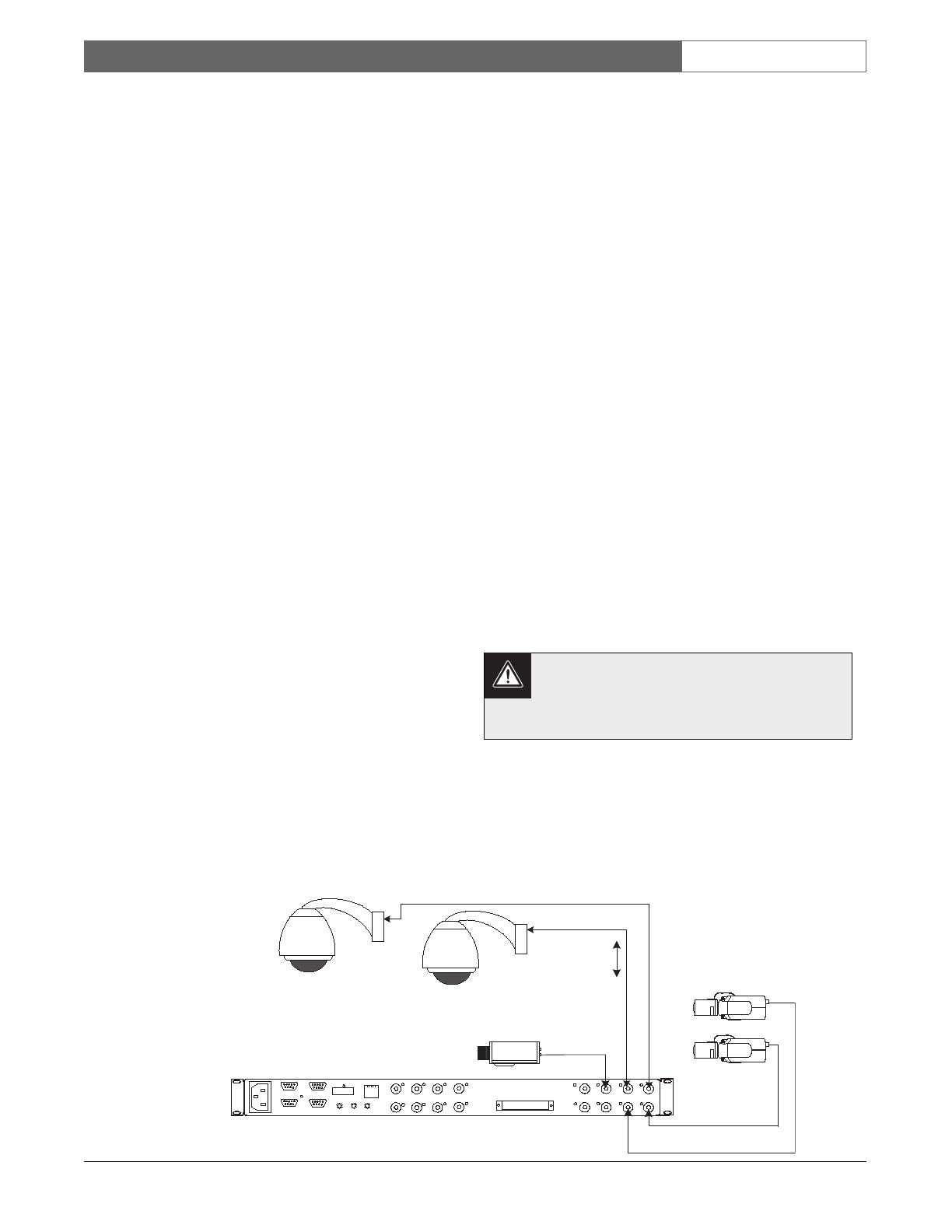
4.3 Camera Video Connections
There are two banks of BNC inputs on the rear panel
of the Interface Unit: 1-8 and 9-16. The inputs are
designed to accept standard composite video signals,
and are fixed at 75Ω termnation. The unit accepts
NTSC or PAL video signals. Both Bilinx and non-
Blinx cameras can be connected to a bank of inputs,
but at least one Bilinx camera must be connected to
the bank in use, or it will enter a search mode and
cause a periodic video disturbance. If more than 8
cameras are connected to the unit, both banks must
have at least one Bilinx camera connected to it.
BILINX TECHNOLOGY PROVIDES
ADJUSTMENT AND CONFIGURATION
CAPABILITIES FOR COMPATIBLE CAMERAS
FROM THE CONTROLLER LOCATION.
THERE’S NO NEED TO PRE-PROGRAM
CAMERA OPTIONS OR CONFIGURE
CAMERA ADDRESSES.
Coax communication must not exceed 300 m
(1000 ft) when using RG-59U grade CCTV
coax, or 600 m (2000 ft) when using RG-6 or
RG-11 grade coax.
There are other types of video transmission devices
that are compatible with Bilinx technology. The
LTC 4630 & LTC 4631 Series can transmit Bilinx
video signals via fiber optics, up to a maximum of
600 m (2000 ft). It is also possible to use CAT-5 grade
cable connected to Balun devices, to achieve distances
of up to 225 m (750 ft).
Video Plus
Bilinx Data
Bilinx-enabled
AutoDome
Series Cameras
16-Channel Bilinx
Interface Unit
PC
INPUTS
15
16
13
14
11
12
9
10
8
6
5
3
4
2
LOOPING VIDEO 1-16
. . . . . . . . . . . . . . . . .
. . . . . . . . . . . . . . . . .
7
1
RS-232
RS-485 IN
RS-485 OUT
DATA
ETHERNET
10/100 BaseT
ACTLINK
CODE
BIPHASE IN
GROUP ID
0
2
6
4
8
0
2
6
4
8
0
2
6
4
8
Bilinx-enabled
Dinion Series
Cameras
Conventional
Camera
(Non-Bilinx)
BOSCH
Figure 1 Typical Video Connections to Interface Unit

EN
|
9
Bosch Security Systems | 18 August 2005
LTC 8016/90 | Instruction Manual | Installation
NOTE: The video signal and Bilinx control
data require unobstructed two-way
communication. Do not place active video
devices in the coax line, because it will block
the control data signals.
Passive devices, such as ground loop isolation
transformers or other devices specifically designed to
support Bilinx communication, can be placed in the
coax line. In some configurations, it may be possible
to connect an active device after the video passes
through the head-end control unit. For sample
applications, refer to the Typical Configuration Diagrams
Section found later in this manual.
When an operating camera is connected to the
Interface Unit, the video channel LED illuminates
GREEN to indicate the presence of an acceptable
video signal. As Bilinx control data is sent to or
received from Bilinx-enabled cameras, the respective
channel LED flashes accordingly.
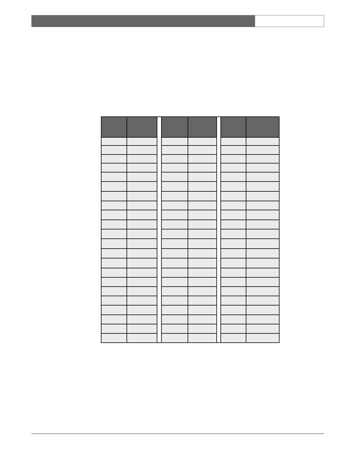
4.4 Group ID Number
The rear panel of the Interface Unit contains a set of
3 rotary switches, as shown below. Use the straight
slot side of the supplied offset screwdriver to set the
switches to the necessary value.
These switches are used to identify the group of
cameras to be connected to the Interface Unit. Each
group consists of 16 cameras in consecutive order,
and the group must always end at an exact multiple
of 16. For example, the lowest camera group range
is from 1 to 16. The next group range is from
17 to 32, etc., up to the last group (camera range of
9985 to 9999). If multiple Interface Units are used in
the same system, each Group ID number must be
unique.
The following chart summarizes the supported switch
settings:
When the Interface Unit is connected to an Allegiant
system using the Allegiant data interface protocol,
the Group ID switches should always be set to
correspond to the physical camera numbers used in
the system. For control systems that use the biphase
data interface, the switches should be set to
correspond to the controller’s logical camera
configuration.
After a change is made in a large Allegiant system
with multiple Interface Units, 30 seconds may be
required before the new settings take effect in all
Interface Units.
Setting 900 is reserved for factory use. If the Interface
Unit is inadvertently set to this value for more than
5 seconds before being set to its correct value, a
power off/on may be required for the unit to return
to its normal operating mode.
Select the step below that applies to your specific
system configuration.
BOSCH
POWER / DATA
Allegiant Bilinx Data Interface
Interface
Data
LTC 8016/90
Video + Data
NVT-211 or
NVT-213A Baluns
(Sold separately)
LTC 4631
F/O Module
Fiber Cable Length
600 m ( 2000 ft) max
Typical CAT-5
UTP Cable
225 m (750 ft)
max
LTC 4630
F/O Module
Coax
Coax
Bilinx-enabled
AutoDomes
Allegiant or Biphase
Control System
Switch Setting Use
001 to 625 Valid switch settings used for Allegiant and biphase
controller interfaces
901 to 931 Settings used in Allegiant interface mode to
terminate RS-485 data line
000 Reserved; setting is used during firmware upgrades
900 Reserved; setting is used by the factory
GROUP ID
0
2
6
4
8
0
2
6
4
8
0
2
6
4
8
Figure 2 Interface Unit Used with Other Video
Transmission Technologies

EN
|
10
Bosch Security Systems | 18 August 2005
LTC 8016/90 | Instruction Manual | Installation
4.4.1 Group ID Settings When Using Allegiant
RS-232 or RS-485 Protocol
When using the Allegiant data interface protocol, the
Group ID must be set to correspond to a block of 16
physical camera numbers between 1-16 and 481-496.
Since each block consists of 16 numbers, the Group
ID number for these cameras ranges from 1 to 31.
Select a Group ID number that does not duplicate
another Group ID number.
A special case exists when multiple units are cascaded
using the Interface Unit’s RS-485 data connection
(explained later). The left-most Group ID switch on
the last unit must be set to 9, to terminate the data
link.
For example, if a total of 32 Bilinx-enabled cameras
will be connected using the range of Allegiant inputs
17-32 and 49-64, one of the Interface Units must be
set to Group ID 002, and the other to 004. If the
Interface Unit for cameras 49-64 is the last unit
connected at the end of the RS-485 data link, its
actual Group ID should be set to 904.
If only one Interface Unit will be connected to
support Bilinx cameras on inputs 1 to 16, no change
is required from the Interface Unit’s default setting
of 901.
Set the Group ID switches using the supplied
screwdriver, as follows:
1
The last unit must be set to terminate the RS-485 data line, by
setting the left-most Group ID switch to 9.
If the Allegiant’s camera number assignments will be
changed (using the Allegiant Master Control Software
package) to use logical camera numbers other than
the default physical input numbers, Interface Units
with Group ID ranging from 1 to 31 are automatically
notified of the new settings, by the Allegiant system.
This allows the system to support random camera
numbers.
NOTE: If the Allegiant’s logical camera number
assignments are changed as described above, then
downloaded into the Allegiant CPU, the update
process may take up to 30 seconds. Camera control
functions will not be available until this update has
completed.
Group ID
Switches
1
Camera
Number
Range
Group ID
Switches
1
Camera
Number
Range
001 1 to 16 017 257 to 272
002 17 to 32 018 273 to 288
003 33 to 48 019 289 to 304
004 49 to 64 020 305 to 320
005 65 to 80 021 321 to 336
006 81 to 96 022 337 to 352
007 97 to 112 023 353 to 368
008 113 to 128 024 369 to 384
009 129 to 144 025 385 to 400
010 145 to 160 026 401 to 416
011 161 to 176 027 417 to 432
012 177 to 192 028 433 to 448
013 193 to 208 029 449 to 464
014 209 to 224 030 465 to 480
015 225 to 240 031 481 to 496
016 241 to 256
EN
|
11
Bosch Security Systems | 18 August 2005
LTC 8016/90 | Instruction Manual | Installation
4.4.2 Switch Settings When Interfacing to Biphase
Controller Devices
When using a biphase data interface, the Group
ID switches must be set to correspond to a block
of 16 logical camera numbers between 1-16 and
9985-9999. Since each block consists of 16 numbers,
the Group ID number for these cameras range from
1 to 625. The Group ID number selected must not
duplicate Group ID numbers already used.
The Interface Unit is set to 901 by default, and no
change is required when only one Interface Unit is
used in a system for cameras 1 to 16. Otherwise, use
the supplied screwdriver to set the Group ID
to correspond to the logical camera number range
shown in the table below. For larger systems, refer
to APPENDIX A for additional Group ID switch
settings.
Group ID
Switches
Camera
Number
Range
Group ID
Switches
Camera
Number
Range
Group ID
Switches
Camera
Number
Range
001 1 to 16 023 353 to 368 045 705 to 720
002 17 to 32 024 369 to 384 046 721 to 736
003 33 to 48 025 385 to 400 047 737 to 752
004 49 to 64 026 401 to 416 048 753 to 768
005 65 to 80 027 417 to 432 049 769 to 784
006 81 to 96 028 433 to 448 050 785 to 800
007 97 to 112 029 449 to 464 051 801 to 816
008 113 to 128 030 465 to 480 052 817 to 832
009 129 to 144 031 481 to 496 053 833 to 848
010 145 to 160 032 497 to 512 054 849 to 864
011 161 to 176 033 513 to 528 055 865 to 880
012 177 to 192 034 529 to 544 056 881 to 896
013 193 to 208 035 545 to 560 057 897 to 912
014 209 to 224 036 561 to 576 058 913 to 928
015 225 to 240 037 577 to 592 059 929 to 944
016 241 to 256 038 593 to 608 060 945 to 960
017 257 to 272 039 609 to 624 061 961 to 976
018 273 to 288 040 625 to 640 062 977 to 992
019 289 to 304 041 641 to 656 063 993 to 1008
020 305 to 320 042 657 to 672 064 1009 to 1024
021 321 to 336 043 673 to 688
022 337 to 352 044 689 to 704
EN
|
12
Bosch Security Systems | 18 August 2005
LTC 8016/90 | Instruction Manual | Installation
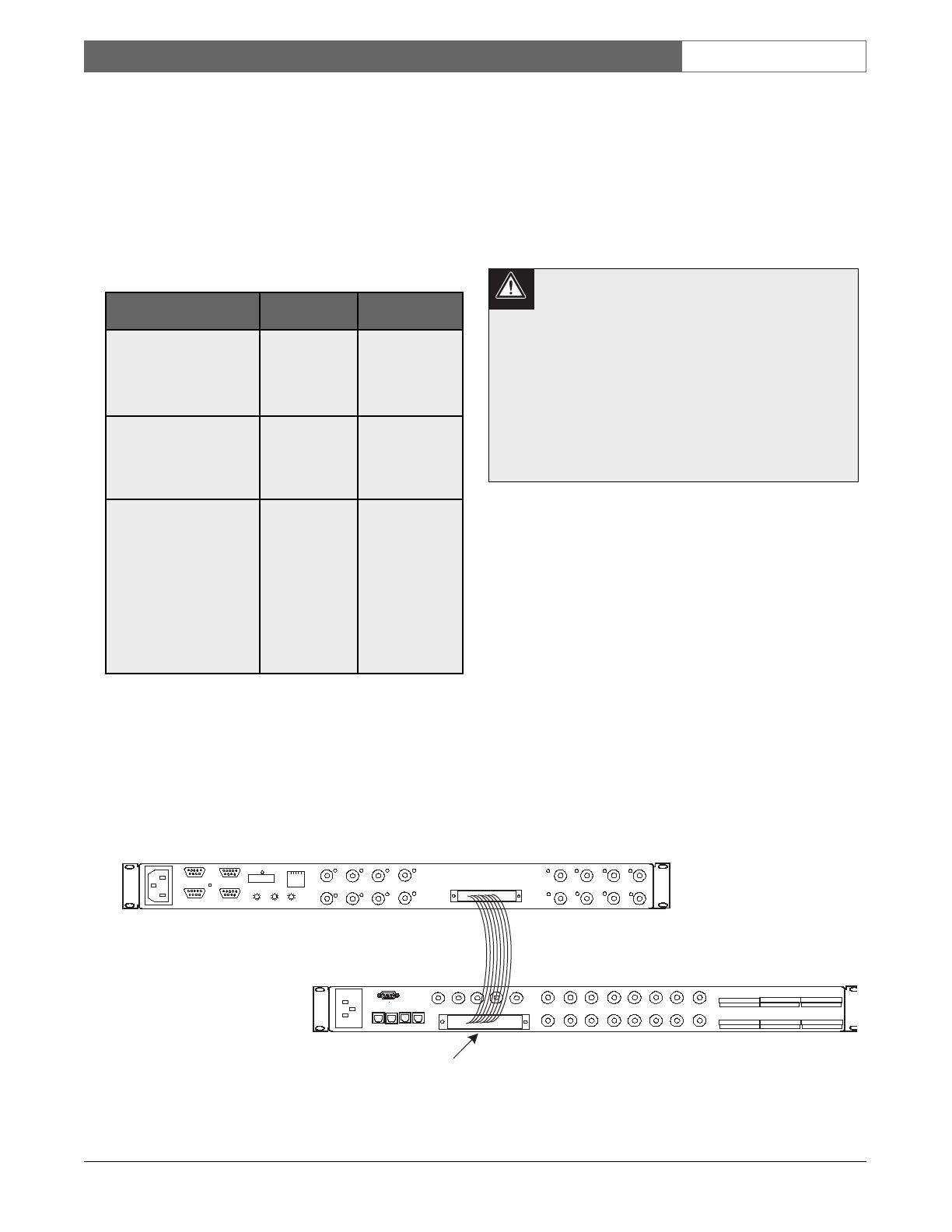
4.5 Video Connections to
the Controller Unit
Video connections from the Interface Unit vary based
on the type of video connections available on the
controller, and the distance between the controller
and the Interface Unit. Review the options in the
table below to determine which best suits your
configuration, then follow the appropriate section
below:
Video output signals from the Interface Unit are
expecting to see a standard 75Ω termination. Unless a
video input will be used to loop out to another device,
make sure that the video inputs on the control unit are
properly set to provide 75Ω video termination. For
details on setting the video terminations of your
controller device, refer to the device’s installation
instructions.
The video connections from the Interface Unit MUST
be kept in consecutive order, and the group must
always end at an exact multiple of 16. For example,
the lowest camera group range is from 1 to 16. The
next group range is from 17 to 32, and so on, up to
the last group, that corresponds to the camera range
of 9985 to 9999. Always make video connections to
the controller following these guidelines.
Certain controller units support video looping
inputs. Do not connect a camera to the
looping output of a video channel on the
control unit that is already being used by the
Interface Unit. Smeared or double video
images will result. Alternate video
connections available on video control
systems should only be used for looping
video signals out to some other external
control system device or monitor.
4.5.1 Video Connections to Products Supporting
Ribbon Cable Interface
Video connections from the Interface Unit to Allegiant
models LTC 8200, LTC 8300, LTC 8600, LTC 8800,
LTC 8900, and the DESA
XL
Series Digital Video
Recorders use the supplied video ribbon cable. Noting
the video ribbon cable connector’s orientation and
alignment tab, connect one end of the supplied
16-channel ribbon cable to the back of the Interface
Unit. Place the other end into the connector on the
rear panel of the controller unit that corresponds to the
physical camera number range previously determined
by the Group ID switch settings (described above). For
example, if the Group ID switches have been set to
003, the video ribbon cable should be installed into
the Allegiant connector corresponding
to video inputs 33 to 48.
LTC 8016 Interface Unit
2m (6ft) Supplied
Video Ribbon Cable
LTC8200
KEYBOARD
CONSOLE
MONITOR OUTPUTS
CAMERA INPUTS
ALARM 1-8
BIPHASE OUT
BIPHASE OUT
RELAY OUT
1
9
2
10
3
11
4
12
5
13
14
6
7
15
8
16
5
4
1
2
3
. . . . . . . . . . . . . . . . .
. . . . . . . . . . . . . . . . .
ALARM 9-16
BIPHASE OUT
PC
INPUTS
15
16
13
14
11
12
9
10
8
6
5
3
4
2
LOOPING VIDEO 1-16
. . . . . . . . . . . . . . . . .
. . . . . . . . . . . . . . . . .
7
1
RS-232
RS-485 IN
RS-485 OUT
DATA
ETHERNET
10/100 BaseT
ACTLINK
CODE
BIPHASE IN
GROUP ID
0
2
6
4
8
0
2
6
4
8
0
2
6
4
8
LTC 8200 Allegiant Series Switcher
Video Looping
Ribbon Connector
Figure 3 Interface Unit Video Connections to a Typical Allegiant System
Controller Type Configuration
Method
Max Separation
Distance
Allegiant Series LTC 8200,
LTC 8300, LTC 8600,
LTC 8800, and LTC 8900,
DESA
XL
DVR Series
Use 16-channel
video ribbon
cable, supplied
with the
LTC 8016
2 m (6 ft)
Any controller system
using BNC connectors
Use the optional
LTC 8508/01
16-channel
ribbon-to-BNC
video cable
1 m (3 ft)
Any controller system
using BNC connectors
Use the
16-channel
video ribbon
cable supplied
with the
LTC 8016, to
the optional
LTC 8807/00
panel, then
BNC to user-
supplied video
link
Distance is
limited only by
the type of user-
supplied video
transmission link
EN
|
13
Bosch Security Systems | 18 August 2005
LTC 8016/90 | Instruction Manual | Installation
1 m (3 ft)
LTC 8508/01
Ribbon-to-BNC
Cable (Purchased
Separately)
PC
INPUTS
15
16
13
14
11
12
9
10
8
6
5
3
4
2
LOOPING VIDEO 1-16
. . . . . . . . . . . . . . . . .
. . . . . . . . . . . . . . . . .
7
1
RS-232
RS-485 IN
RS-485 OUT
DATA
ETHERNET
10/100 BaseT
ACTLINK
CODE
BIPHASE IN
GROUP ID
0
2
6
4
8
0
2
6
4
8
0
2
6
4
8
Connect to Video Input
Connectors on Control Unit
16 BNC
Connectors
LTC 8016 Interface Unit
BOSCH
Divar Digital Versatile Recorder
SEARCH
B
ACK
ALT
1 2 3 4 5 6 7 8 9 10 11 12 13 14 15 16LIVE
F2F1
ESC
A
Figure 4 Typical Video Connections to Divar Series DVR Control Units
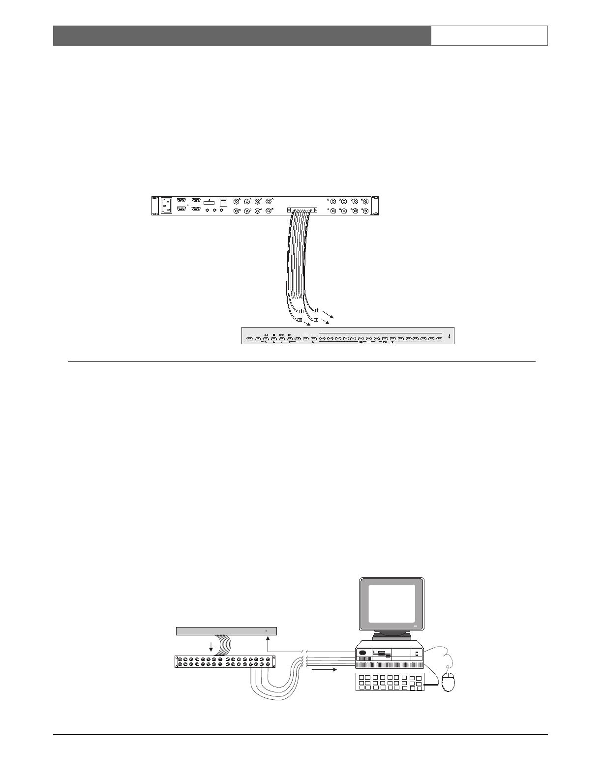
Figure 5 Video Connections to Control System Located at Remote Site
4.5.2 Video Connections to Products via
LTC 8508/01 Ribbon-to-BNC Cable
Video connections to Allegiant models LTC 8100,
LTC 8500, and other products using BNC video
connectors, can utilize the 1 m (3 ft) 16-channel
LTC 8508/01 Ribbon-to-BNC cable (sold separately).
One LTC 8508 cable is required for each Interface
Unit being installed. Noting the connector orientation
and alignment tab, connect the ribbon connector end
of the cable to the Interface Unit. Attach the BNC
ends to the video inputs on the rear panel of the
controller that corresponds to the physical camera
number range previously determined by the Group ID
switch settings above. For example, if the Group ID
switches have been set to 001, the BNC ends of the
video ribbon cable should be installed in the
controller’s video inputs 1 to 16. For your convenience,
the BNC ends are marked with the video channel
number.
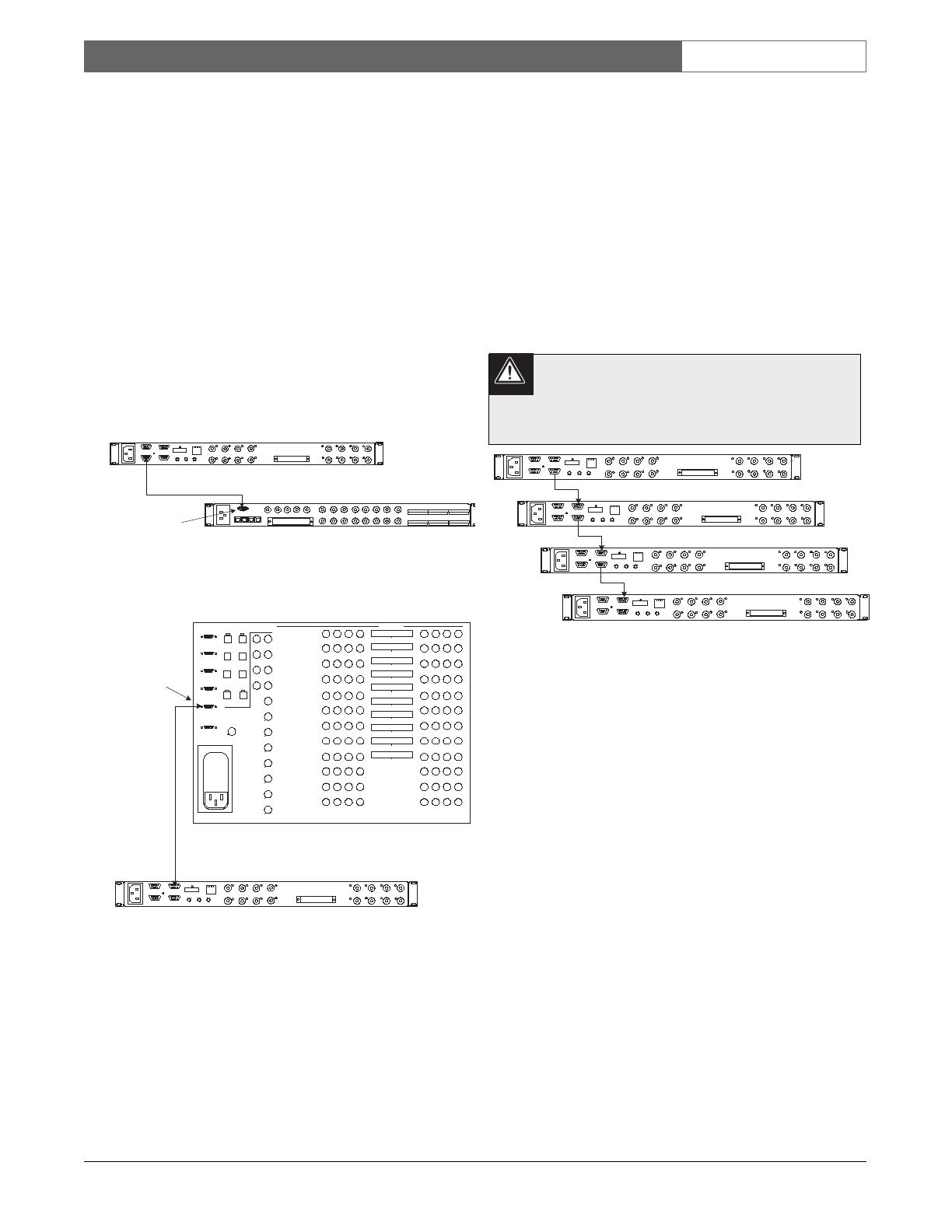
4.5.3 Video Connections to Products via
LTC 8807/00 Video Interconnect Panel
If using a rack-mountable BNC patch panel, or if the
Interface Unit will be remoted some distance from the
controller unit, an LTC 8807/00 Video Interconnect
Panel (sold separately) can be used for video
connections to a controller. Each LTC 8807 panel can
be used with up to two Interface Units, supporting a
maximum of 32 cameras. Connect the supplied video
ribbon cable from the Interface Unit into the upper
connector on the back of the LTC 8807 for the first
block of 16 cameras. The lower connector is only used
if a second Interface Unit will be connected, providing
a second block of 16 cameras.
User-supplied coax jumper cables are required to
complete the video connections between the LTC 8807
panel and the BNC connectors on the controller unit.
Attach the coax to the video inputs on the rear panel
of the controller bay, that correspond to the physical
camera number range previously determined by the
Group ID switch settings above. For example, if the
Group ID switches have been set to 001, the coax
cables should be installed into the controller’s video
inputs 1 to 16.
If the control unit will be located at a remote distance
from the Interface Unit, standard practices for video signal
transmission, and the associated data interface, should be
used (more details provided in the next section).
Typical Remoted DVR
or Other Biphase-
enabled Controller
BOSCH
POWER
Interface
Data
Customer-supplied
Video Coax
LTC 8807/00 Interconnect Panel
(sold separately) for use with up to
two (2) LTC 8016 units
Video
Signals
LTC 8016/90
Interface Unit
Supplied 16-Channel
LTC 8809 Video Cable
Follow Standard
Practices for Remoting
Coax & Data Cables

EN
|
14
Bosch Security Systems | 18 August 2005
LTC 8016/90 | Instruction Manual | Installation
4.6 Allegiant Series Switcher Data
Interface
4.6.1 Allegiant Interface Configurations
When using the Allegiant data interface protocol, up
to 31 Interface Units can be connected to a single
large Allegiant system. In this configuration, bi-
directional Bilinx communication to physical cameras
ranging from 1 to 496 is supported. In very large
systems, additional units can be interfaced to the
Allegiant via biphase data connection.
When connecting to an Allegiant system, select a data
port on the main Allegiant CPU that will be used to
communicate with the Interface Unit. The Interface
Unit provides separate interface connectors so it is able
to support both RS-232 and RS-485 Allegiant interfaces.
Only one port on the Interface Unit can be
used at a time. Connecting data cables to
more than one port on the Interface Unit
simultaneously could result in non-operation.
4.6.1.1 Allegiant Interface Port Selection
Based on the Allegiant model being used, select an
available CPU port from the table below. Note that it
is not possible to connect the Interface Unit cable to a
Console port provided by an Allegiant LTC 8712
Series Port Expander accessory unit.
The ALARM port requires a special cable
pinout. DO NOT USE the supplied cable for
this port connection. A cable must be
constructed by the installer, per the pinouts
shown in the CONNECTOR & CABLE
PINOUTS Section.
4.6.1.2 Setting the Allegiant System to Use Bilinx
Communication Mode
Using Allegiant Keyboard User Function 39, a system
keyboard operator with Level 1 Priority must configure
the Allegiant to enable the communication interface on
the selected port.
IntuiK
ey S
eries Keyboard:
From the main Allegiant screen, navigate to the User
Functions menu screen, then press [Enter User
Command]. Key in 39, then press [Enter].
L
TC 8555 or LTC 8550 Series Keyboard:
Press [USER], key in 39, then press [Enter].
The monitor’s on-screen text will indicate the current
configuration mode, such as NO DIU OPERATION
(i.e., meaning No D
ata Interface Unit Operation) on
a non-configured system. Use the keyboard joystick
up/down to navigate through the available port
options. Enter the operator password when prompted,
and press [Enter] to select the port currently shown.
The port is now configured with the proper baud rate
and handshake settings to communicate with the
Interface Unit.
If the on-screen option reads No CTS
Operation, the CPU firmware version is older
than the revision needed for compatibility with
Bilinx communication. On Allegiant systems
sold after 1995, CPU upgrades can be done
from an external PC using a software
download approach. Older systems
(i.e., having CPU modules with a single
8-position dip switch) can be upgraded by
replacing the CPU module. Contact the
nearest Bosch Security Systems Sales
Representative or Tech Support specialist for
additional details on Allegiant CPU upgrades.
A system reset is required to complete the process.
Either use Keyboard User Function 15, or power
off/on the main Allegiant CPU bay. The Allegiant is
then ready to communicate with the Interface Unit.
Allegiant
Model
Supported Ports
CONSOLE PRINTER ALARM1 COM1 COM2
LTC 810 0 YES NO NO NO NO
LTC 8200 YES NO NO NO NO
LTC 8300 YES YES NO NO NO
LTC 8500 YES YES YES NO NO
LTC 8600 YES YES YES YES YES
LTC 8800 YES YES YES YES YES
LTC 8900 YES YES YES YES YES
ALLEGIANT Video Matrix
BOSCH
IntuiKey
Keyboard
Typical Allegiant
System Main CPU Bay
BOSCH
POWER
Allegiant Data
Interface Protocol
LTC 8016/90
Interface Unit
1 2
3
4 5
6
7 8
9
0
Shot
Mon
Prod
Clr
BOSCH
BOSCH
001 PASSWD REQ'ED 12:00:00
NO DIU OPERATION 12-01-04
001 PASSWD REQ'ED 12:00:00
NO DIU OPERATION 12-01-04
Figure 6 Allegiant On-screen Setup Procedure for
Bilinx Operation
EN
|
15
Bosch Security Systems | 18 August 2005
LTC 8016/90 | Instruction Manual | Installation
4.6.2 Allegiant Data Connections Using a Single
Interface Unit
Use the supplied 3 m (10 ft) data interface cable to
connect the Allegiant to the Interface Unit. Connect
one end of the cable to the Allegiant port selected in
the previous section, and the other end of the cable to
the Interface Unit port, according to the following
guide:
If an Allegiant CONSOLE, PRINTER, or ALARM
port is being used, connect the cable to the RS-232
connector on the rear of the Interface Unit.
If an Allegiant COM1 or COM2 port is being used,
connect the cable to the RS-485 IN connector on the
rear of the Interface Unit.
Once a connection is established between the
Interface Unit and the Allegiant, an automatic
download of the Allegiant’s physical camera-to-
logical camera table is sent to the Interface Unit.
Prior to this update, the front panel LED on the
Interface Unit flashes to indicate that it is waiting for
the information to be received. Once the LED
changes to a steady condition, configuration is
complete.
4.6.3 Allegiant Data Connections Using Multiple
Interface Units
Up to 31 units can be connected to a single
Allegiant switcher, using a daisychain data interface
configuration. This provides support for up to
496 Bilinx cameras. Since the same data is being sent
to all Interface Units in the chain, it does not matter
what order is used when connecting the data lines
between the units. Simply connect the supplied
3 m (10 ft) data interface cable from the RS-485 OUT
connector of one Interface Unit to the RS-485 IN of
the next unit.
To properly terminate the RS-485 data
connection, the last Interface Unit in the series
(i.e., furthest from the Allegiant switcher) must
have its left-most Group ID set to 9.
Daisychain configurations can only be used when the
data connection from the controller to the Interface
Unit utilizes either an RS-232 or RS-485 data port.
Do not use this method if the data connection from a
controller uses the biphase data port.
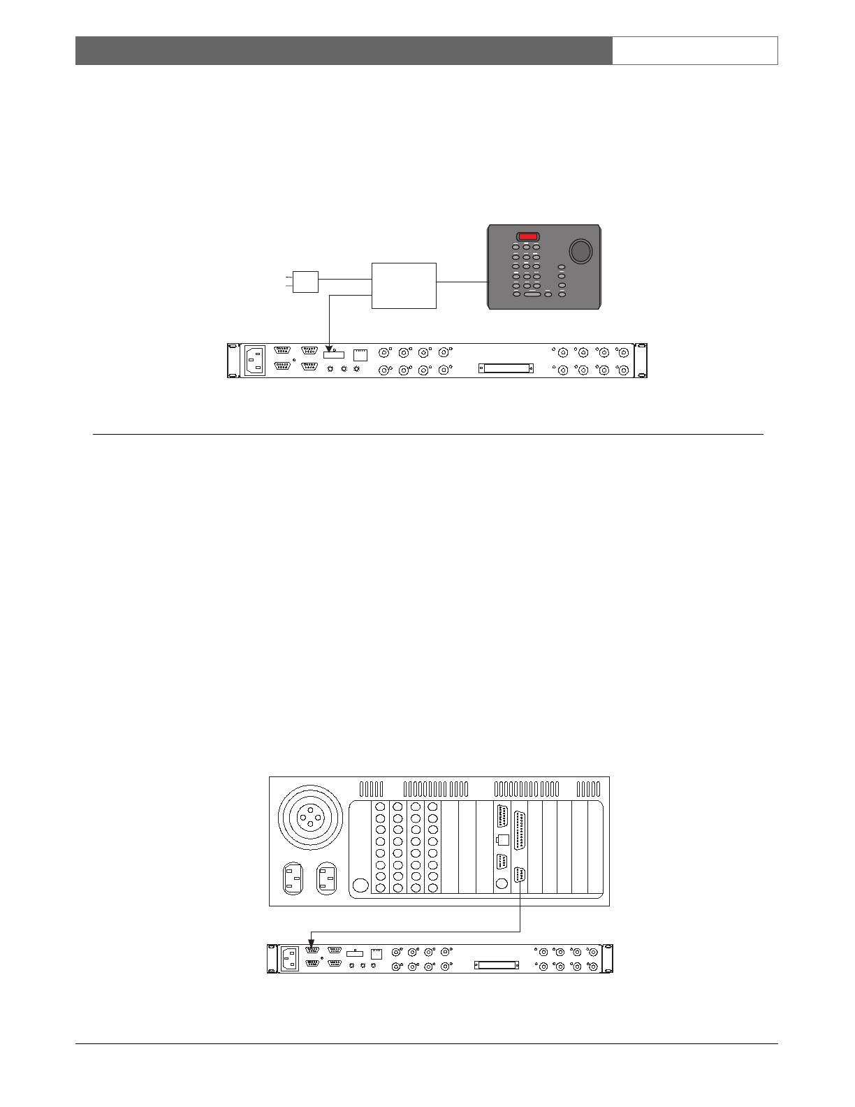
4.7 Data Connection to a Biphase
Generating Device
The Interface Unit is designed to support data
connections from other head-end controller devices
with the ability to generate Bosch Security Systems
biphase control data. Since biphase protocol is a
single direction communication format, control of
P/T/Z functions, auxiliaries, and pre-positions are
fully supported, but it is not possible to receive any
data back from the camera site. This means that
reporting of alarms or other camera site-related events
is not possible with a biphase data connection.
LTC 8016 Interface Unit
2 m (6 ft) Supplied
Data Interface Cable
LTC8200
KEYBOARD
CONSOLE
MONITOR OUTPUTS
CAMERA INPUTS
ALARM 1-8
BIPHASE OUT
BIPHASE OUT
RELAY OUT
1
9
2
10
3
11
4
12
5
13
14
6
7
15
8
16
5
4
1
2
3
. . . . . . . . . . . . . . . . .
. . . . . . . . . . . . . . . . .
ALARM 9-16
BIPHASE OUT
PC
INPUTS
15
16
13
14
11
12
9
10
8
6
5
3
4
2
LOOPING VIDEO 1-16
. . . . . . . . . . . . . . . . .
. . . . . . . . . . . . . . . . .
7
1
RS-232
RS-485 IN
RS-485 OUT
DATA
ETHERNET
10/100 BaseT
ACTLINK
CODE
BIPHASE IN
GROUP ID
0
2
6
4
8
0
2
6
4
8
0
2
6
4
8
LTC 8200 Allegiant Series Switcher
Allegiant
CONSOLE Port
LTC 8016 Interface Unit
2m (6ft) Supplied
Data Interface Cable
PC
INPUTS
15
16
13
14
11
12
9
10
8
6
5
3
4
2
LOOPING VIDEO 1-16
. . . . . . . . . . . . . . . . .
. . . . . . . . . . . . . . . . .
7
1
RS-232
RS-485 IN
RS-485 OUT
DATA
ETHERNET
10/100 BaseT
ACTLINK
CODE
BIPHASE IN
GROUP ID
0
2
6
4
8
0
2
6
4
8
0
2
6
4
8
LTC 8600 Allegiant Series Switcher
Allegiant
COM Port 1
Figure 8 Data Interface Connection Detail When
Using Large Model Allegiant System
Figure 7 Data Interface Connection Detail When
Using Large Model Allegiant System
2m (6ft) Supplied
Data Interface Cable
PC
INPUTS
15
16
13
14
11
12
9
10
8
6
5
3
4
2
LOOPING VIDEO 1-16
. . . . . . . . . . . . . . . . .
. . . . . . . . . . . . . . . . .
7
1
RS-232
RS-485 IN
RS-485 OUT
DATA
ETHERNET
10/100 BaseT
ACTLINK
CODE
BIPHASE IN
GROUP ID
0
2
6
4
8
0
2
6
4
8
0
2
6
4
8
PC
INPUTS
15
16
13
14
11
12
9
10
8
6
5
3
4
2
LOOPING VIDEO 1-16
. . . . . . . . . . . . . . . . .
. . . . . . . . . . . . . . . . .
7
1
RS-232
RS-485 IN
RS-485 OUT
DATA
ETHERNET
10/100 BaseT
ACTLINK
CODE
BIPHASE IN
GROUP ID
0
2
6
4
8
0
2
6
4
8
0
2
6
4
8
PC
INPUTS
15
16
13
14
11
12
9
10
8
6
5
3
4
2
LOOPING VIDEO 1-16
. . . . . . . . . . . . . . . . .
. . . . . . . . . . . . . . . . .
7
1
RS-232
RS-485 IN
RS-485 OUT
DATA
ETHERNET
10/100 BaseT
ACTLINK
CODE
BIPHASE IN
GROUP ID
0
2
6
4
8
0
2
6
4
8
0
2
6
4
8
PC
INPUTS
15
16
13
14
11
12
9
10
8
6
5
3
4
2
LOOPING VIDEO 1-16
. . . . . . . . . . . . . . . . .
. . . . . . . . . . . . . . . . .
7
1
RS-232
RS-485 IN
RS-485 OUT
DATA
ETHERNET
10/100 BaseT
ACTLINK
CODE
BIPHASE IN
GROUP ID
0
2
6
4
8
0
2
6
4
8
0
2
6
4
8
2m (6ft) Supplied
Data Interface Cable
2m (6ft) Supplied
Data Interface Cable
Up to 31 units total (when using large Allegiant System Controller)
Figure 9 Data Interface Connection Detail When
Using Multiple Interface Units
EN
|
16
Bosch Security Systems | 18 August 2005
LTC 8016/90 | Instruction Manual | Installation
LTC 8016 Interface Unit
PC
INPUTS
15
16
13
14
11
12
9
10
8
6
5
3
4
2
LOOPING VIDEO 1-16
. . . . . . . . . . . . . . . . .
. . . . . . . . . . . . . . . . .
7
1
RS-232
RS-485 IN
RS-485 OUT
DATA
ETHERNET
10/100 BaseT
ACTLINK
CODE
BIPHASE IN
GROUP ID
0
2
6
4
8
0
2
6
4
8
0
2
6
4
8
LTC 5136 Series Controller
LTC 5136
Data
Converter
Unit
Power
Supply
Adaptor
RS-232
Data &
Power
Biphase Control
Code Output
Figure 10 Biphase Data Interface Connection Detail
LTC 8016 Interface Unit
PC
INPUTS
15
16
13
14
11
12
9
10
8
6
5
3
4
2
LOOPING VIDEO 1-16
. . . . . . . . . . . . . . . . .
. . . . . . . . . . . . . . . . .
7
1
RS-232
RS-485 IN
RS-485 OUT
DATA
ETHERNET
10/100 BaseT
ACTLINK
CODE
BIPHASE IN
GROUP ID
0
2
6
4
8
0
2
6
4
8
0
2
6
4
8
Typical PC-based DVR Unit
Biphase RS-232
Code Output Data
User-supplied Cable (see text)
Figure 11 Biphase RS-232 Data Interface Connection Detail
To connect the Interface Unit to a biphase controller,
attach the biphase data cable from the controller to the
biphase input terminal block on the rear panel of the
Interface Unit. Use the straight slot end of the supplied
offset screwdriver to tighten the terminal block screws.
The Interface Unit supports daisychain biphase
connections to simplify connection to multiple
Interface Units. If this type of connection is necessary,
remove the termination resistor from the biphase
output terminal block, and connect another user-
supplied shielded twisted pair cable from the output of
one Interface Unit to the input of another.
4.8 Data Connections Using Biphase
RS-232 Protocol
The Interface Unit can be connected directly to Bosch
Security System products that generate biphase control
data in RS-232 format. These products include the
PC-based DiBos, and DESA Series Digital Video
Recorders.
Typically, the RS-232 interface of the controller first
connects to an optional LTC 8786 or LTC 8780 Data
Converter accessory unit. The outputs from the Data
Converter Unit can be connected to P/T/Z cameras or
other devices designed to receive standard biphase
code protocol.
Although the LTC 8016 is capable of receiving
standard biphase protocol, it can also directly accept
biphase in an RS-232 format. Any controller capable
of generating biphase data in an RS-232 format
operating at 9600, 19200, 57600, or 115200 baud,
with 8 data bits, no parity, and 1 stop bit, can be
connected to the Interface Unit.
When RS-232 communication is first established,
the Interface Unit may require 3 to 5 seconds to
automatically detect and adjust to the controller’s
baud rate. No control of cameras is possible until
this process is completed.
Refer to the portion of the next section that is
applicable to your configuration, based on the
controller product being connected to the
Interface Unit.
EN
|
17
Bosch Security Systems | 18 August 2005
LTC 8016/90 | Instruction Manual | Typical Configuration Diagrams
4.8.1 Connecting to DiBos Digital Video
Recorders
A RS-232 grade data cable (not supplied) is required
to connect the DiBos DVR to the LTC 8016 Interface
Unit. A Bosch Security System’s S1385 cable can be
purchased separately, or one can be constructed based
on the pinouts in the CONNECTOR AND CABLE
PINOUTS Section.
Connect one end of the RS-232 data cable to an
available COM port on the DiBos, and the other end
of the cable to the PC port on the Interface Unit. The
DiBos software must now be configured to send the
biphase PTZ commands out the COM port. For
details on this configuration option, refer to the
appropriate section in the DiBos instruction manual.
4.8.2 Connecting to DESA and DESA-8 Series
Digital Video Recorders
A RS-232 grade data cable (not supplied) is required
to connect the DESA DVR to the LTC 8016 Interface
Unit. A Bosch Security System’s S1385 cable can be
purchased separately, or one can be constructed based
on the pinouts in the CONNECTOR AND CABLE
PINOUTS Section.
Connect one end of the RS-232 data cable to the
COM2 port on the DESA, and the other end of the
cable to the PC port on the Interface Unit. The
DESA software must now be configured to send the
biphase PTZ commands out of its COM2 port (rather
than the default COM1 port). For details on this
configuration option, refer to the appropriate section
in the DESA instruction manual.
4.8.3 Connecting to DESA
XL
Series Digital
Video Recorders
A user-supplied RS-232 grade data cable is required to
connect the DESA
XL
DVR to the LTC 8016 Interface
Unit. The interface cable must either be purchased
locally, or constructed based on the pinouts in the
CONNECTOR AND CABLE PINOUTS Section.
Connect one end of the RS-232 data cable to the end
of the Watchdog/PTZ cable connected to the DESA’s
COM1 port, and the other end of the cable to the PC
port on the Interface Unit.
Data
Video + Data
Control
Data
Typical DVR or Other biphase-
enabled Controller
BOSCH
POWER
Biphase
Data
1 m LTC 8508/01
16-Channel Ribbon-
to-BNC Cable
(sold separately)
Video
Signals
16-Channel
LTC 8016/90
Allegiant Bilinx
Interface Unit
Bilinx-enabled
AutoDomes
Bilinx-enabled
Dinion Series
Cameras
BOSCH
Divar Digital Versatile Recorder
SEARCH
B
ACK
ALT
1 2 3 4 5 6 7 8 9 10 11 12 13 14 15 16LIVE
F2F1
ESC
A
Video
Video
BOSCH
Figure 12 Typical Interface Unit Connected to DVR Control Unit
5.0 TYPICAL CONFIGURATION
DIAGRAMS
EN
|
18
Bosch Security Systems | 18 August 2005
LTC 8016/90 | Instruction Manual | Typical Configuration Diagrams
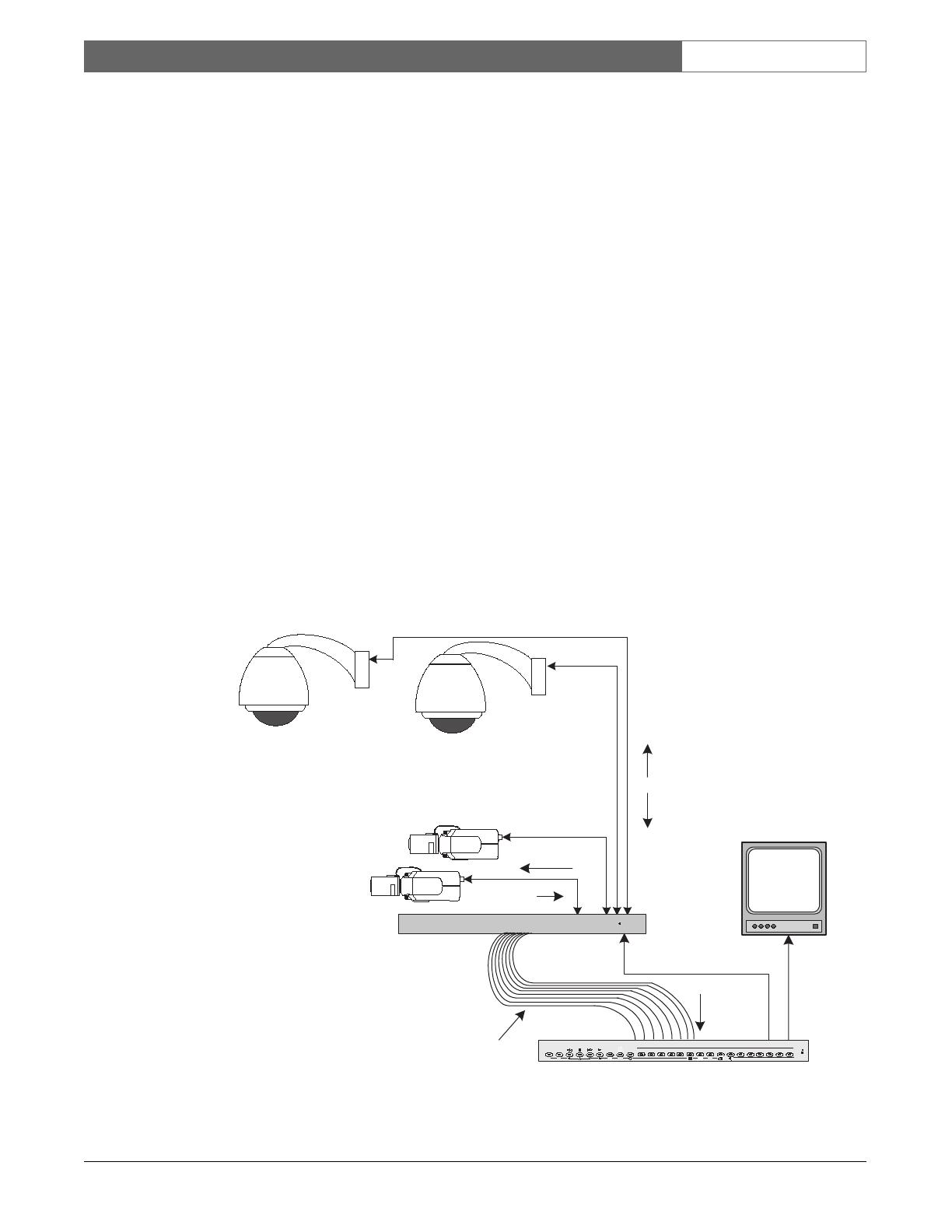
ALLEGIANT Video Matrix
BOSCH
BOSCH BOSCH
Video
Only
IntuiKey
Keyboard
Video Plus
Bidirectional Data
System Monitors
Typical Allegiant
System Main CPU Bay
Supplied 16-Channel
LTC 8809 Video Cable
Bilinx-enabled
AutoDomes
BOSCH
POWER
Data
16-Channel
LTC 8016/90
Allegiant Bilinx
Interface Unit
1
2
3
4 5 6
7 8
9
0
Shot
MonProd
Clr
BOSCH
BOSCH
Conventional Camera
Video + Data
Bilinx-enabled
Dinion Series
Cameras
Video + Data
Video
Signals
Max Cable Lengths:
RG-59U = 300 m (1000 ft)
RG-6 or RG-11 = 600 m (2000 ft)
LTC 8555
Figure 13 Typical Interface Unit Connected to Allegiant Switching System
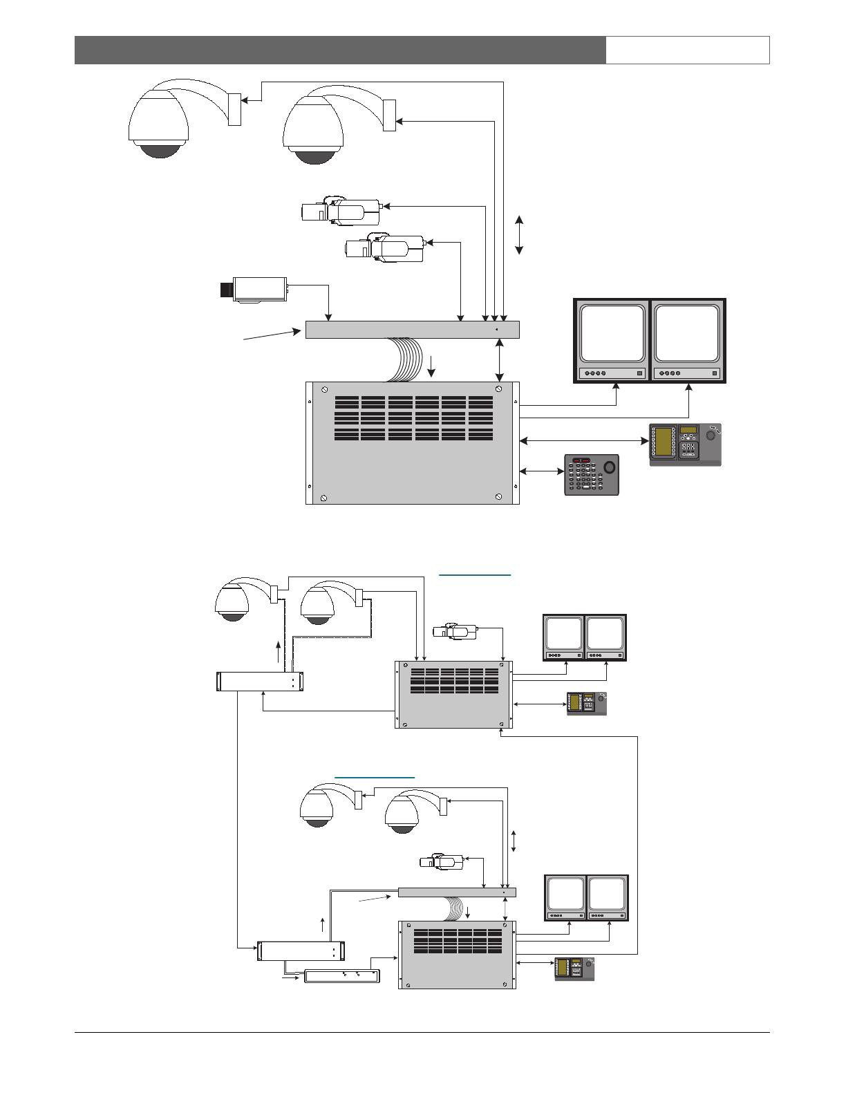
ALLEGIANT Video Matrix
BOSCH
IntuiKey Keyboard
Video
Allegiant Satellite
System
ALLEGIANT Video Matrix
BOSCH
Video
BOSCH
ALLEGIANT Data Unit
CODE
POWER
LTC 8568 Signal
Distribution Unit
Biphase
Code
Video
Allegiant Master
System
Biphase Data
Video
IntuiKey Keyboard
Satellite Video Trunk Line(s)
BOSCH
ALLEGIANT Data Unit
CODE
POWER
LTC 8569 Code
Merger Unit
CODE OUT
RS-232 IN
RS-232 OUT
CODE IN
ON
LTC 8780
Biphase
Code
1 2
3
4 5
6
7 8
9
0
Shot
MonProd
Clr
BOSCH
1
2
3
4
5
6
7 8
9
0
Shot
MonProd
Clr
BOSCH
Video Plus
Bidirectional Data
Supplied 16-Channel
LTC 8809 Video Cable
Bilinx-enabled
AutoDomes
BOSCH
POWER
Data
LTC 8016/90
Video + Data
Bilinx-enabled
Dinion Series
Camera
Video + Data
Video
Signals
BOSCH BOSCH
BOSCH BOSCH
Biphase
Input
Satellite
Data
Biphase
Code
Master Site
Satellite Site
(Control of P/T/Z and camera menu access
of satellite cameras supported via biphase
signal, but no camera events available)
(Control of P/T/Z, access to camera menus,
and camera events available via Bilinx)
Figure 14 Interface Unit Used in Allegiant Satellite System Configuration
EN
|
19
Bosch Security Systems | 18 August 2005
LTC 8016/90 | Instruction Manual | Typical Configuration Diagrams
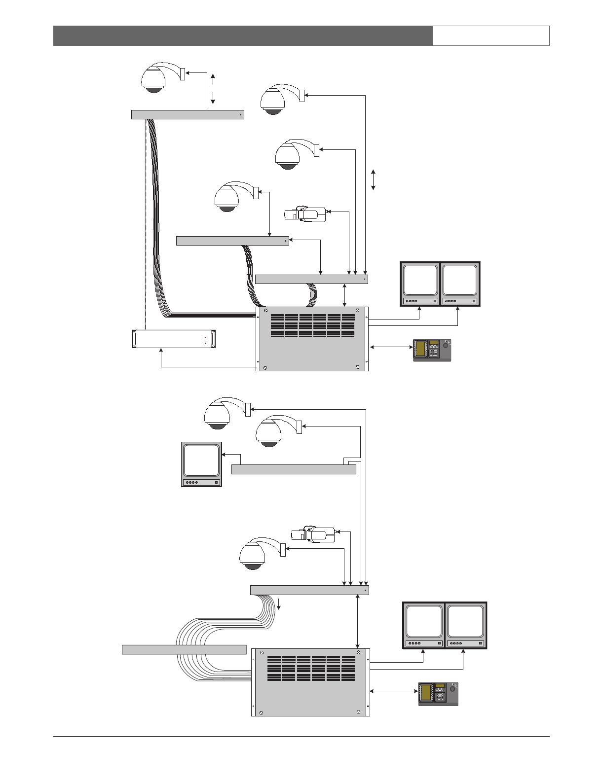
ALLEGIANT Video Matrix
BOSCH
BOSCH BOSCH
Video + Data
IntuiKey Keyboard
Video
System Monitors
Large Allegiant
Matrix System
BOSCH
POWER / DATA
Allegiant Bilinx Data Interface
Interface
Data
LTC 8016/90
Additional LTC 8016/90
units can be connected
via the Biphase data
interface, but full
bidirectional functionality
will not available
Loop Through
Interface Data
1 2
3
4
5
6
7
8
9
0
Shot
MonProd
Clr
BOSCH
BOSCH
POWER / DATA
Allegiant Bilinx Data Interface
Bilinx-enabled
Dinion Series
Cameras
LTC 8016/90
Bilinx-enabled
AutoDomes
BOSCH
ALLEGIANT Data Unit
CODE
POWER
LTC 8568 Signal
Distribution Unit
Biphase Data
BOSCH
POWER / DATA
Allegiant Bilinx Data Interface
Up to 31 LTC 8016 units
can be cascaded,
providing full support
for up to 496 Bilinx-
enabled cameras
Control
Data
Video
Video Plus
Bidirectional Data
Supplied 16-Channel
LTC 8809 Video Cable
LTC 8016/90
Bilinx-enabled
AutoDome
STP Cable
Figure 15 Large Allegiant System with Several Interface Units
BOSCH BOSCH
Video + Data
IntuiKey Keyboard
Video
Allegiant System
Video
BOSCH
POWER / DATA
Allegiant Bilinx Data Interface
Interface
Data
LTC 8016/90
Video + Data
Typical Quad, multiplexer or
other device having passive
video looping inputs
BOSCH
Video Loop
1
2
3
4
5
6
7
8
9
0
Shot
MonProd
Clr
BOSCH
1 m LTC 8508/01
16-Channel Ribbon-
to-BNC Cable
(sold separately)
Typical Video
Motion Detector
or other device
having active
video looping
inputs
ALLEGIANT Video Matrix
BOSCH
User-
supplied
Coax
Figure 16 Recommended Configuration When Using Bilinx with Other Devices
EN
|
20
Bosch Security Systems | 18 August 2005
LTC 8016/90 | Instruction Manual | Operation
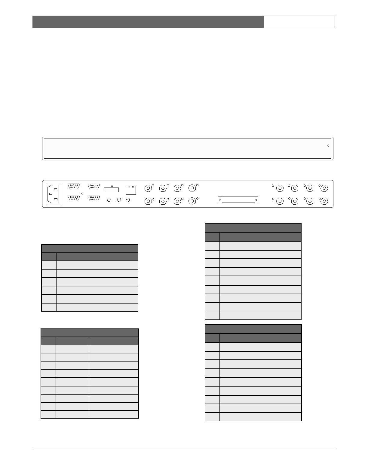
7.0 DEVICE OUTLINE
8.0 CONNECTOR AND CABLE PINOUTS
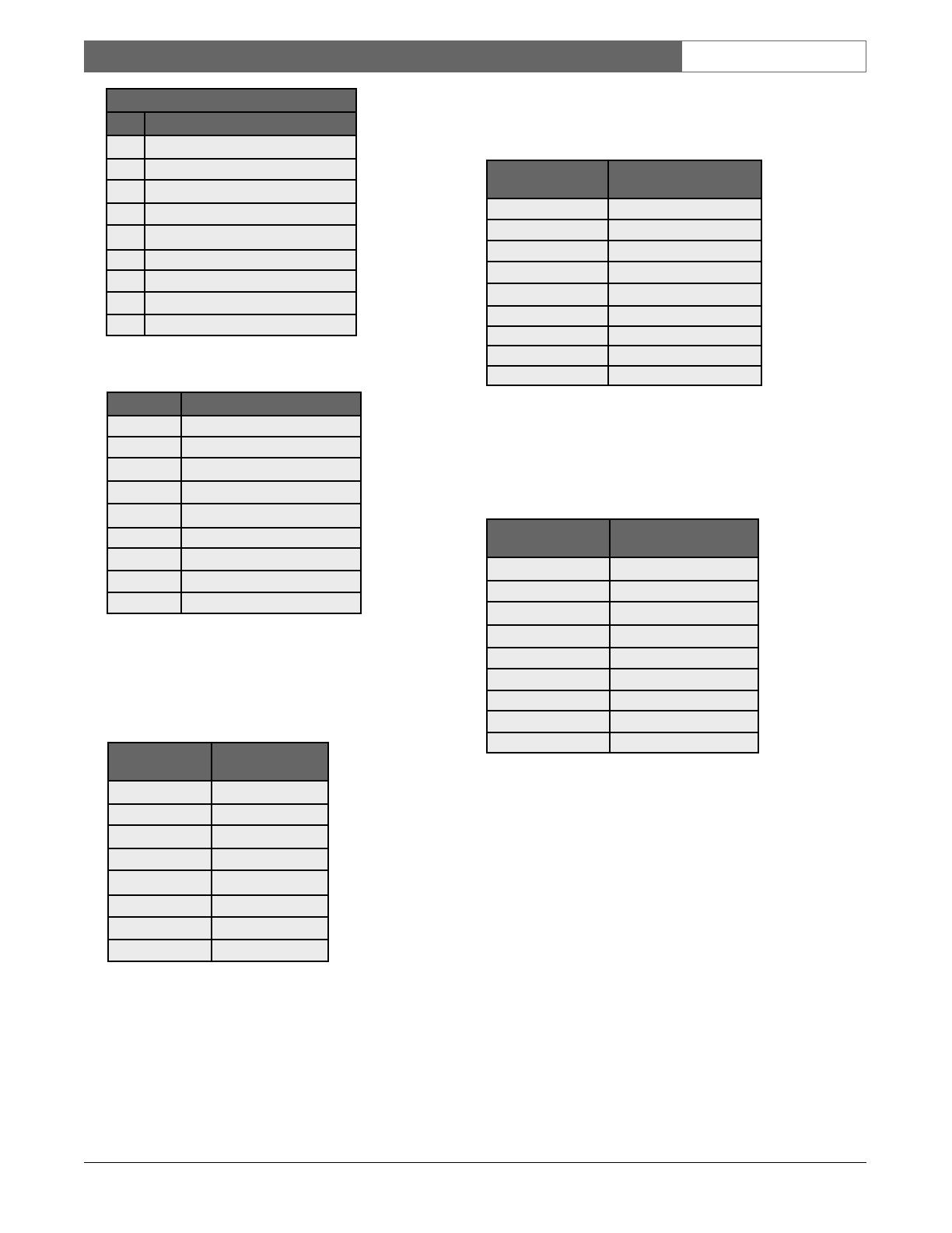
8.1 LTC 8016 Connector Pinouts
1
Pins are not numbered; the numbers represent
the pin sequence from left to right.
2
Pinouts used on units manufactured before
July, 2004 (date code 0426).
PC
INPUTS
15
16
13
14
11
12
9
10
8
6
5
3
4
2
LOOPING VIDEO 1-16
. . . . . . . . . . . . . . . . .
. . . . . . . . . . . . . . . . .
7
1
RS-232
RS-485 IN
RS-485 OUT
DATA
ETHERNET
10/100 BaseT
ACTLINK
CODE
BIPHASE IN
GROUP ID
0
2
6
4
8
0
2
6
4
8
0
2
6
4
8
Figure 18 Rear Panel
6-Position CODE Connector
1
Pin Connection
1 Shield
2 Biphase Data --
3 Biphase Data +
4 Shield
5 Biphase Data --
6 Biphase Data +
9-Pin PC Connector
Pin Connection Old Pinouts
2
1 –– ––
2 Rx Tx
3 Tx Rx
4 –– ––
5 Data Gnd Data Gnd
6 –– ––
7 RTS CTS
8 CTS RTS
9 –– ––
9-Pin RS-232 Connector
Pin Connection
1 Data Gnd
2 RTS
3 CTS
4 Tx
5 Rx
6 ––
7 Data Gnd
8 ––
9 ––
9-Pin RS-485 IN Connectors
Pin Connection
1 ––
2 TXD+
3 TXD--
4 RXD+
5 RXD--
6 ––
7 ––
8 ––
9 ––
6.0 OPERATION
Once installation is finished, operation of this unit is
completely automatic. Refer to the applicable section of
the manual supplied with the control device and/or
camera for details regarding their features/functions.
The Interface Unit is designed to process camera
contact alarm and motion event messages from cameras
that support this functionality. The Interface Unit can
also detect Dark Alarm signal conditions when the
video amplitude level drops below 15 IRE. When the
Interface is connected to an Allegiant system using the
Allegiant data interface, messages can be sent to the
controller to notify the system of these events. By
default, camera contact alarm input 1 will result in a
standard Allegiant system alarm response, assuming an
alarm response mode has been configured in the
system. System responses to camera alarms 2 to 4, and
the Dark Alarm require programming of the Allegiant
system using the PC-based Allegiant LTC 8059 Master
Control Software, version 2.7 or later.
Allegiant Bilinx Data Interface
BOSCH
Status/Power
Figure 17 Front Panel
EN
|
21
Bosch Security Systems | 18 August 2005
LTC 8016/90 | Instruction Manual | Maintenance
8.2 Supplied Serial Data Cable Pinouts
8.3 Miscellaneous Cables (Not supplied)
Bosch S1385 or Industry standard Null modem
RS-232 Data Cable (Required if connecting the
LTC 8016 directly to the COM port on PC)
1
The PC connector on units manufactured
before July, 2004 (date code 0426) used
a male 9-pin connector for this port.
Industry type straight through RS-232 Data
Cable (Required if connecting the LTC 8016 to a
Watchdog/PTZ connector on the DESA
XL
DVR)
2
The PC connector on units manufactured before
July, 2004 (date code 0426) used a male 9-pin
connector for this port.
9-Pin to 9-Pin Serial Data Cable for Allegiant Alarm
Port (Required if connecting the LTC 8016 to the
Allegiant Alarm Port)
9.0 MAINTENANCE
The Allegiant Bilinx Data Interface Unit does not
require any special maintenance.
9-Pin RS-485 OUT Connectors
Pin Connection
1 ––
2 RXD+
3 RXD--
4 TXD+
5 TXD--
6 ––
7 ––
8 ––
9 ––
9-Pin Male 9-Pin Male
1 ––
2 4
3 5
4 2
5 3
6 ––
7 ––
8 ––
9 ––
9-Pin Female
(PC COM Port)
9-Pin Female
1
(LTC 8016 PC)
1,6 4
2 3
3 2
4 1,6
5 5
7 8
8 7
9 ––
9-Pin Male
(Alarm Port)
9-Pin Male
(LTC 8016 RS-232 Port)
1RTS 3CTS
2Tx 5Rx
3 Chassis Gnd ––
4 Data Gnd 1 Data Gnd
5 Data Gnd 7 Data Gnd
6Rx 4Tx
7CTS 2RTS
8 No Connection ––
9 No Connection ––
9-Pin Male
(DVR COM Port)
9-Pin Female
2
(LTC 8016 PC Port)
1 1
2 2
3 3
4 4
5 5
6 6
7 7
8 8
9 9
Page is loading ...
Page is loading ...
Page is loading ...
/