Page is loading ...

Commercial Series
Radio CP160
User Guide
6866550D05-O
Issue: December 2003

1
8
4
2
3
5
P1
P2
6
7
11
9
10
12
13

1
English
CONTENTS
CONTENTS
Computer Software Copyrights . . . . . . . . . 2
RadioOverview .................... 3
Operation and Control Functions . . . . . . . . 3
Radio Controls . . . . . . . . . . . . . . . . . . . 3
Programmable Buttons . . . . . . . . . . . . . 4
Indicator Tones . . . . . . . . . . . . . . . . . . . 8
Battery Charge Status. . . . . . . . . . . . . . 9
LED Indicator . . . . . . . . . . . . . . . . . . . . 9
LCD Display and Icons . . . . . . . . . . . . 10
Menu Buttons . . . . . . . . . . . . . . . . . . . 11
Menu Navigation Chart . . . . . . . . . . . . 12
GettingStarted.................... 13
Battery Information. . . . . . . . . . . . . . . . . . 13
Charging Your Battery. . . . . . . . . . . . . 13
Desktop Rapid Charger. . . . . . . . . . . . 14
Accessory Information . . . . . . . . . . . . . . . 15
Attaching the Battery. . . . . . . . . . . . . . 15
Removing The Battery . . . . . . . . . . . . 15
Attaching The Antenna . . . . . . . . . . . . 16
Removing The Antenna . . . . . . . . . . . 16
Attaching The Belt Clip . . . . . . . . . . . . 17
Removing The Belt Clip . . . . . . . . . . . 17
Turning the Radio On or Off . . . . . . . . . . .18
Radio On Message . . . . . . . . . . . . . . . . . .18
Adjusting the Volume. . . . . . . . . . . . . . . . .18
Selecting a Radio Channel . . . . . . . . . . . .19
Home Revert Memory Channel (1&2) . . . .19
Store Memory Channel (1&2) . . . . . . . . . .19
Receiving a Call. . . . . . . . . . . . . . . . . . . . .20
Sending a Call . . . . . . . . . . . . . . . . . . . . . .20
Monitoring . . . . . . . . . . . . . . . . . . . . . . . . .21
VOX Operation . . . . . . . . . . . . . . . . . . . . .21
Connecting a VOX Headset . . . . . . . . .21
Enable/Disable Headset Sidetone. . . . . . .22
VOX Headset . . . . . . . . . . . . . . . . . . . .22
Non-VOX Headset With In-Line PTT . .22
Keypad Lock/Unlock . . . . . . . . . . . . . . . . .22
RadioCalls........................23
Receiving a Selective Call . . . . . . . . . . . . .23
Sending a Selective Call . . . . . . . . . . . . . .23
Receiving a Call Alert Page . . . . . . . . . . . .24
Sending a Call Alert Page . . . . . . . . . . . . .24
Repeater Or Talkaround Mode . . . . . . . . .25

2
English
CONTENTS
Scan............................. 27
Start System Scan . . . . . . . . . . . . . . . . . . 27
Stop System Scan . . . . . . . . . . . . . . . . . . 28
Start Auto Scan . . . . . . . . . . . . . . . . . . . . 28
Stop Auto Scan . . . . . . . . . . . . . . . . . . . . 28
Talkback. . . . . . . . . . . . . . . . . . . . . . . . . . 28
Delete a Nuisance Channel . . . . . . . . . . . 29
Restore Channels to the Scan List . . . 29
Edit a Scan List . . . . . . . . . . . . . . . . . . . . 29
Add or Delete Channels . . . . . . . . . . . . . . 30
Prioritize a Channel in a Scan List . . . . . . 31
Set Priority Channels . . . . . . . . . . . . . 31
Phone ........................... 33
Access the Repeater . . . . . . . . . . . . . . . . 33
Receive a Phone Call. . . . . . . . . . . . . . . . 33
Disconnect a Phone Call . . . . . . . . . . . . . 34
Make a Phone Call. . . . . . . . . . . . . . . . . . 34
Tone Preferences. . . . . . . . . . . . . . . . . . 35
Tones On/Off . . . . . . . . . . . . . . . . . . . . . . 37
Keypad On/Off Tones . . . . . . . . . . . . . . . 37
Call Tone Tagging . . . . . . . . . . . . . . . . . . 38
Escalert . . . . . . . . . . . . . . . . . . . . . . . . . . 38
UserSettings......................39
Set Squelch Level . . . . . . . . . . . . . . . . . . .41
Set Power Level . . . . . . . . . . . . . . . . . . . .41
Option Board On/Off . . . . . . . . . . . . . . . . .42
Set the Lights. . . . . . . . . . . . . . . . . . . . . . .42
Display the Software Version . . . . . . . . . .43
C
omputer
S
o
f
tware
C
opyr
i
g
h
t
The products described in this manual may include copyrighted computer
programmes stored in semiconductor memories or other media. Laws in the
United States of America and other countries preserve for Motorola Europe
and Motorola Inc. certain exclusive rights for copyrighted computer
programmes, including the right to copy or reproduce in any form the
copyrighted computer programme. Accordingly, any copyrighted computer
programmes contained in the products described in this manual may not be
copied or reproduced in any manner without the express written permission of
the holders of the rights. Furthermore, the purchase of these products shall not
be deemed to grant either directly or by implication, estoppel, or otherwise, any
licence under the copyrights, patents, or patent applications of the holders of
the rights, except for the normal non-exclusive royalty free licence to use that
arises by operation of the law in the sale of the product.

3
English
RADIO OVERVIEW
RADIO OVERVIEW
This user guide covers the operation of the CP160
Portable Radios.
ATTENTION!
This radio is restricted to occupational use only to
satisfy ICNIRP RF energy exposure requirements.
Before using this product, read the RF energy
awareness information and operating instructions in
the Product Safety and RF Exposure booklet
(Motorola Publication part number 6864117B25_) to
ensure compliance with RF energy exposure limits.
OPERATION AND CONTROL FUNCTIONS
Radio Controls
The numbers below refer to the illustrations on the
inside front cover.
1. Push-to-talk (PTT)
Press and hold down this button to talk;
release it to listen.
2. On-Off / Volume Knob
Used to turn the radio on or off, and to adjust
the radio’s volume.
3. Channel Selector Knob
Used to switch the radio to different channels.
4. LED Indicators
Indicate radio status:
Green: Solid during power up routine; off after
successful power up; flashing when scanning.
Red: Solid - transmitting; Flashing when
transmitting - low battery:
Flashing - channel is busy receiving.
Yellow: Solid when radio is in monitor mode,or
is sending a selective call or call alert;
Flashing - receiving a selective call or call alert.
5. Microphone/Speaker
Hold the microphone 2.5 to 5 cm (1-2 inches)
from your mouth, and speak clearly into it.
6. LCD Display
An 8 character single line display with up to 9
radio status icons.
7. Front Button P2
J
JJ
J
8. Menu Scroll Buttons L M
9. Front Button P1
K
KK
K
10. Side Button 2
11. Side Button 1
12. Accessory Connector
Connects remote microphones, remote
earphones and other accessories. Replace dust
cap when not in use.
13. Belt Clip
Before using this product, read the
operating instructions for safe usage
contained in the Product Safety and
RF Exposure booklet 6864117B25_
enclosed with your radio.
!
Caution

4
English
RADIO OVERVIEW
Programmable Buttons
Your radio has four programmable buttons. Your
dealer can program these buttons as shortcuts to
various radio features.
Check with your dealer for a complete list of
functions your radio supports.
Programmable buttons include:
• Side Buttons (S1 and S2)
• Front Buttons (
K and J)
Some buttons can access up to two features,
depending on the type of button press:
• short press—quickly pressing and releasing the
programmable buttons
• long press—pressing and holding the
programmable buttons for a minimum of 2.5
seconds
• hold down—pressing and holding down the
programmable buttons while checking status or
making adjustments
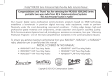
The following table is a summary of programmable
radio features and corresponding page references.
In the “Button” column, have your dealer record the
name of the programmable button next to the
feature that has been programmed to it.
Also, where appropriate, have your dealer indicate
whether the button press requires a short press, a
long press, or needs to be held down.
5
English
RADIO OVERVIEW
Feature Indicator Short Press Long Press Hold Down Page Button
Battery
Indicator
——
Checks the
battery charge
status.
9
Menu Mode —
J button enters Menu Mode and
selects menu options. Once in Menu
Mode,
K button is automaticall
re-assigned to exit Menu Mode.
†
—11
J
Volume Set — — —
Sounds a tone
for adjusting the
radio’s volume
level.
18
Home Revert
Memory
Channel (1&2)
—
Allows instant
access to the
home channel.
——19
Store Memory
Channel (1&2)
—
Stores current
channel to the
home channel.
—19
Monitor
C
A long press initiates Monitor. A short
press cancels Monitor.
Monitors the
selected
channel for any
activity.
21
†
This function is activated by EITHER a short OR a long press, but not both.

6
English
RADIO OVERVIEW
Voice Operated
Transmission
(VOX)
— Toggle VOX on and off.
†
—21
Keypad Lock/
Unlock
L
Toggle keypad
between locked
and unlocked.
22
Radio Call — Directly access radio call menu.
†
—23
Repeater/
Talkaround
J
Toggles between using a repeater or
transmitting directly to another radio.
†
—25
Scan/Nuisance
Channel Delete
G
Starts or stops the
Scan operation.
Deletes a nuisance
channel while
scanning.
—27
Edit Scan List — Add, delete, or prioritize channels.
†
—29
Phone D Directly access Phone mode.
†
—33
Escalert — Toggle escalert on and off.
†
—38
Squelch —
Toggle squelch level between tight and
normal squelch.
†
—41
Power Level B
Toggle transmit power level between
High and Low power.
†
—41
†
This function is activated by EITHER a short OR a long press, but not both.
Feature Indicator Short Press Long Press Hold Down Page Button

7
English
RADIO OVERVIEW
Option Board
A
Toggle the option board on and off.
†
—42
Lights —
Toggle keypad and display backlights
on and off.
†
—42
†
This function is activated by EITHER a short OR a long press, but not both.
Feature Indicator Short Press Long Press Hold Down Page Button
8
English
RADIO OVERVIEW
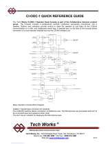
Indicator Tones
High pitched tone Low pitched tone
Some programmable buttons use tones to indicate
one of two modes:
Self Test Pass Tone
Self Test Fail Tone
Positive Indicator Tone
Negative Indicator Tone
Good Key Tone
Bad Key Tone
Programmable
Buttons
Positive
Indicator Tone
Negative
Indicator Tone
Scan Start Stop
Power Level High Low
Squelch Tight Normal
Repeater/
Talkaround
Does not use
repeater
Uses repeater
VOX Enabled Disabled
Silent Monitor/
Open Squelch
— Enabled
Home Revert
Memory
Channel (1&2)
— Enabled
Store Memory
Channel (1&2)
— Stored
Menu Mode J
— Accessed
Radio Call — Enabled
Scan List Edit — Enabled
Phone Mode — Enabled
Option Board Enabled Disabled
Escalert Enabled Disabled

9
English
RADIO OVERVIEW
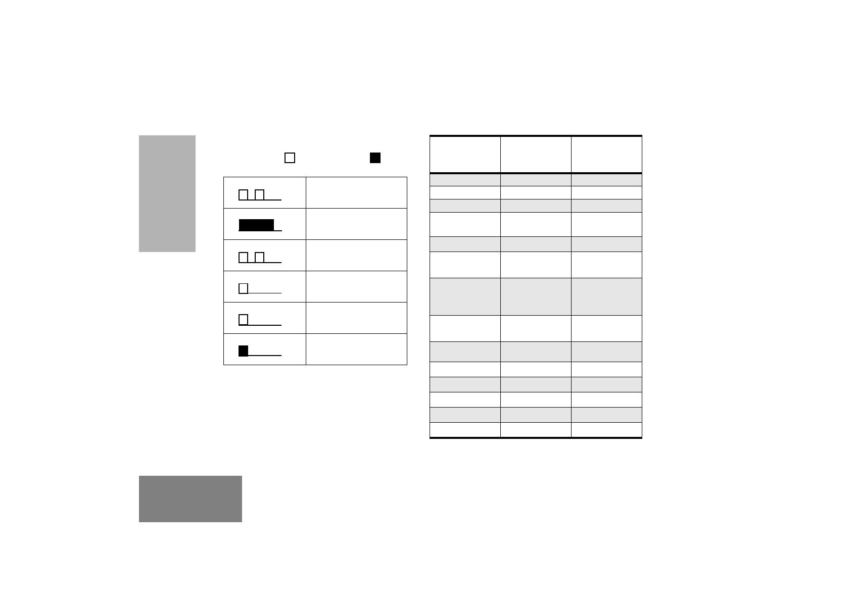
Battery Charge Status
You can check battery charge status if your dealer
has preprogrammed one of the programmable
buttons. Hold down the preprogrammed Battery
Indicator button. The charge status is shown on the
display.
LED Indicator
The LED shows radio status as follows:
Battery Level Display
Full
Good
Fair
Low
Very Low
LED State Indication
Radio Call
Red Solid Radio transmitting.
Red Flashing Receiving.
Red Flashing Channel busy.
Scan
Green Flashing Radio is scanning.
Call Alert
Yellow Flashing Receiving a Call Alert
Yellow Solid Sending a Call Alert
Selective Call
Yellow Flashing Receiving a Selective Call
Yellow Solid Sending a Selective Call
Monitor/Open Squelch
Yellow Solid Radio in monitor mode.
Low Battery Level
Red Flashing Flashing when
transmitting.
10
English
RADIO OVERVIEW
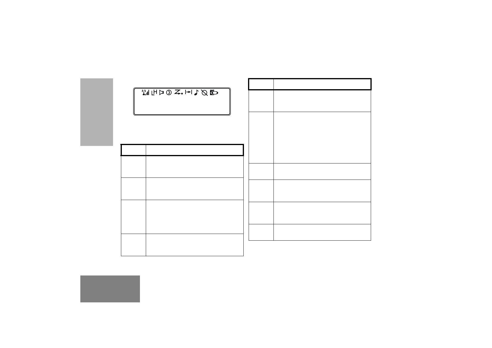
LCD DISPLAY AND ICONS
Displays radio Status, Addresses or Channel, on
one line of 8 characters. The top line of the display
shows radio status icons, explained in the table
below:
Note: At extremely low temperatures, you may
experience a slight delay in displaying new
information. This is normal and does not affect the
function of your radio.
Symbol Name and Description
Option Board Indicator
Indicates that an option board is
activated in the radio.
Signal Strength Indicator
The more bars, the stronger the signal
being received by your radio.
Power Level Indicator
“L” lights when your radio is configured
to transmit in Low Power. “H” lights
when your radio is configured to
transmit in High Power.
Monitor Indicator
The selected channel is being
monitored.
CHAN 32
Scan Indicator
Indicates that the scan feature is
activated.
Priority Scan Indicator
Indicates that the scan feature is
activated. The dot is flashing during
priority scan mode when scan has
landed on a Priority 1 channel.
The dot is steady during priority scan
mode when scan has landed on a
Priority 2 channel.
Phone Indicator
Phone mode is selected.
Call Received Indicator
A Selective Call or Call Alert has been
received.
Talkaround Indicator
You are transmitting directly to another
radio, not via a repeater.
Keypad Lock
The keypad has been locked.
Symbol Name and Description
A
I
B
C
G
H
D
F
J
L

11
English
RADIO OVERVIEW
MENU BUTTONS
Menu Button
If preprogrammed by your dealer, the two front
buttons (
K and J) can be used, in conjunction
with other programmble features, to access and
select menu options (
J); and exit menu mode (K).
The
J button can be preprogrammed by your
dealer to either a short or long press to access the
Menu Mode.
Exit the Menu
While in Menu Mode, the K button is automatically
assigned to completely exit the Menu Mode by a
long press, or by a series of short presses to exit
from a sub-level of the menu hierarchy.
The radio also exits the menu mode if there have
been no inputs via the navigation buttons for the
default “Inactivity Time” or after a selection has been
made.
Once you have exited Menu Mode, the
K and J
buttons return to normal programmable condition.
Menu Scroll Buttons
Used to scroll while in Menu Mode.
Refer to the menu navigation chart for menu
selectable features.
Navigate the Menu
L
or M to scroll through the menu options. If
you scroll past the last option, the selection wraps
around and starts again.
When you reach the required option, a short press
of the
J button selects that option and enters the
sub-menu.
L or M to scroll through the sub-menu options.
Select the option with a short press of the
J button.
12
English
RADIO OVERVIEW
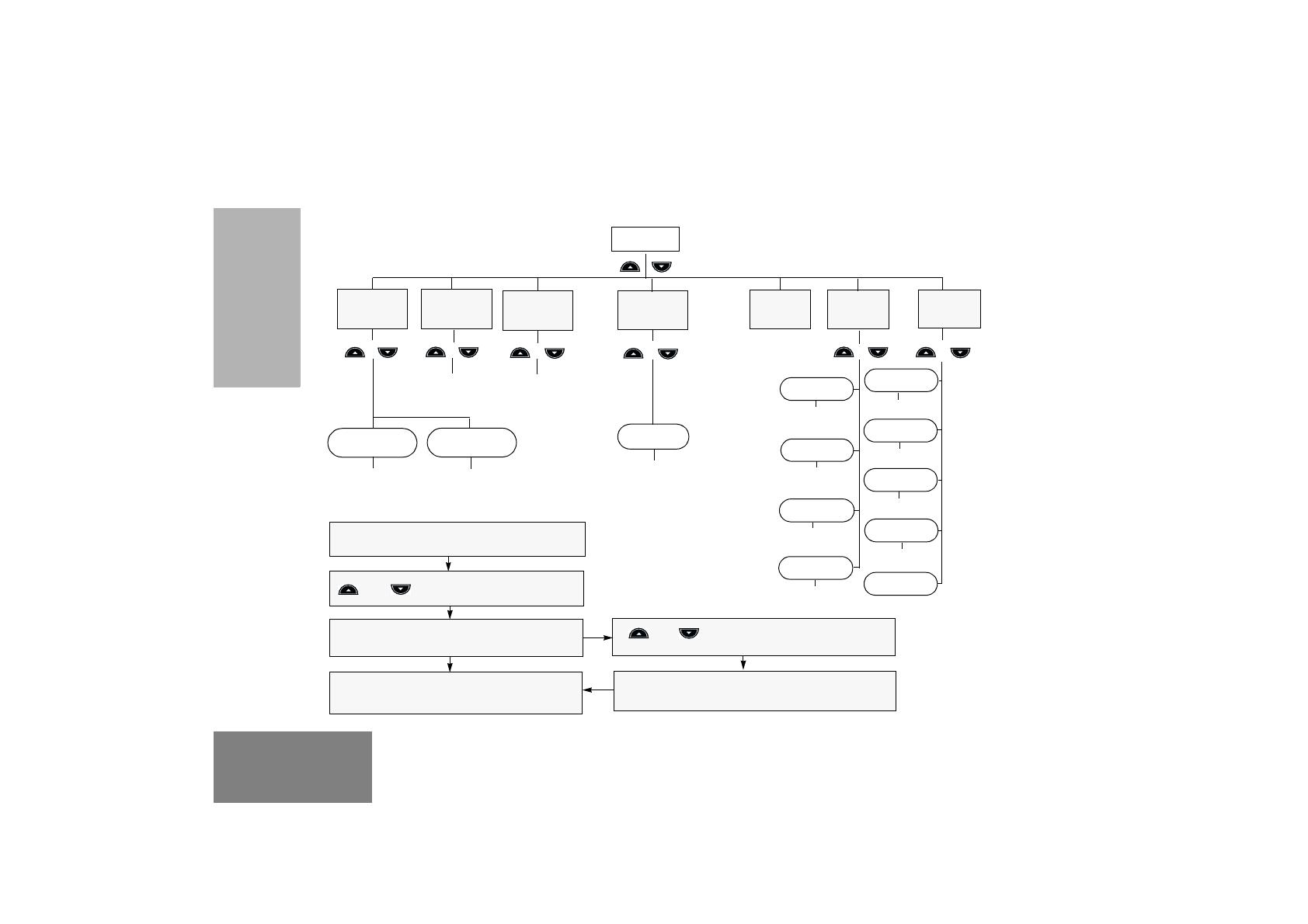
Menu Navigation Guidelines
J
J to enter Menu Mode.
or to scroll through the list.
J to select Menu item
or to scroll through the
Menu sub-list.
J to select sub-menu item.
Select/enter
ID
Reptr mode /
Talkrnd mode
Program
Lists
Tones
Radio
Calls
Scan List
Repeater/
Talkround
On/Off
System
Scan
Utilities
K return to previous menu level
or
Hold down
K to exit Menu Mode
Selective
Call
Call Alert
Select/enter
ID
add/
delete entry
Set prority
Phone
Tone
Tone Tag
Escalert
Keypad
On/Off
On/Off
Standard/alert
1 - 6
On/Off
Squelch
Power Level
Option Bd
Lights
Software Ver
On/Off
On/Off
High/Low
Normal/Tight
MENU NAVIGATION CHART
(Refer to Menu Navigation guidelines—
lower, left-hand corner of this page)

13
English
GETTING STARTED
GETTING STARTED
BATTERY INFORMATION
Charging Your Battery
This radio is powered by a either a nickel-metal
hydride (NiMH), or a lithium-ion (Li-lon)
rechargeable battery. Charge the battery before use
to ensure optimum capacity and performance. The
battery was designed specifically to be used with a
Motorola charger. Charging in non-Motorola
equipment may lead to battery damage and void the
battery warranty.
Note: When charging a battery attached to a radio,
turn the radio off to ensure a full charge.
The battery should be at about 25°C (77°F) (room
temperature), whenever possible. Charging a cold
battery (below 10°C [50°F]) may result in leakage of
electrolyte and ultimately in failure of the battery.
Charging a hot battery (above 35°C [95°F]) results
in reduced discharge capacity, affecting the
performance of the radio. Motorola rapid-rate
battery chargers contain a temperature-sensing
circuit to ensure that batteries are charged within the
temperature limits stated above.
If a battery is new, or its charge level is very low, you
will need to charge it before you can use it. When
the battery level is low and the radio is in transmit
mode you will see the LED indicator flash red. Upon
release of the PTT button, you will hear an alert
tone.
Note: Batteries are shipped uncharged from the
factory. Always charge a new battery 14 to 16
hours before initial use, regardless of the
status indicated by the charger.

14
English
GETTING STARTED
Desktop Rapid Charger
To Charge the Battery
a Remove the battery from the charger and use a
pencil eraser to clean the three metal contacts
on the back of the battery. Replace the battery
in the charger. If the LED indicator continues to
flash red, consult your dealer.
b A standard battery may require 90 minutes to
charge to 90% capacity.
1 Turn the radio off.
2 Place the battery, with or without the radio, in
the charger pocket.
• The charger LED indicates the charging
progress.
LED color Status
No LED Indication Battery inserted incorrectly
or battery not detected.
Single Green Flash Successful charger
power-up.
Flashing Red
a
Battery unchargeable or not
making proper contact.
Red Battery is charging.
Flashing Yellow Battery in charger but
waiting to be charged. The
battery temperature may be
too hot or too cold. The
voltage may be lower than
the predetermined threshold
level for charging.
Flashing Green
b
Battery 90% (or more)
charged.
Green Battery fully charged.

15
English
GETTING STARTED
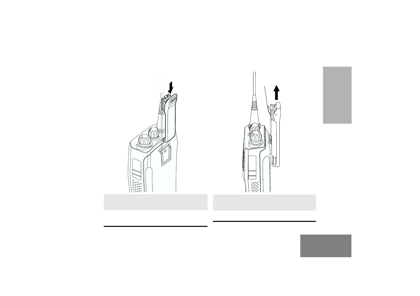
ACCESSORY INFORMATION
Attaching the Battery
Removing the Battery
1 Align the battery to the battery rails on the
back of the radio (approximately 1 cm from the
top of the radio.)
2 Press the battery firmly to the radio and slide
the battery upward until the latch snaps into
place.
3 Slide the battery latch, located on radio
bottom, into the lock position.
1 Turn off the radio if it is turned on.
2 Slide the battery latch into the unlock position.
Disengage by pushing downward and holding
the latch towards the front of the radio.
3 With the battery latch disengaged, slide the
battery down from the top of the radio
approximately 1 cm. Once the battery is free
from the battery rails, lift it directly away from
the radio.
Battery Latch
Locked Un-locked

16
English
GETTING STARTED
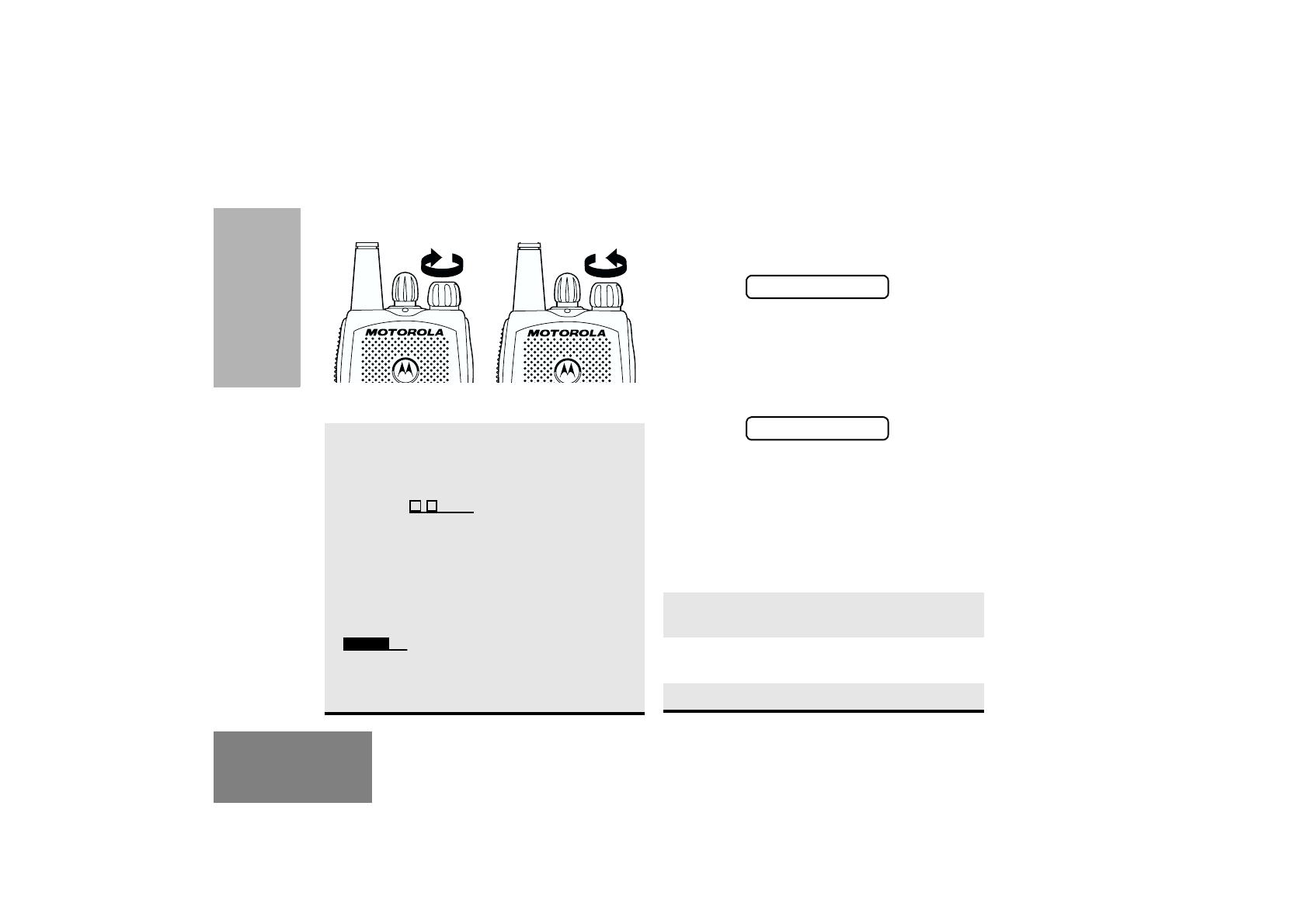
Attaching the Antenna Removing the Antenna
Turn the antenna clockwise to attach it.
Turn the antenna counter-clockwise to remove it.
17
English
GETTING STARTED
Attaching the Belt Clip Removing the Belt Clip
1 Align the grooves of the belt clip with those of
the battery.
2 Press the belt clip downward until you hear a
click.
1 Use a key to press the belt clip tab away from
the battery to unlock the belt clip.
2 Slide the belt clip upward to remove it.
Belt Clip Tab
18
English
GETTING STARTED
TURNING THE RADIO ON OR OFF RADIO ON MESSAGE
At power up the radio may display a message
customised by your dealer, e.g.:
After this text has been displayed, the radio
performs a self test routine. During the routine the
Green LED lights. On completion of a successful
self test the radio produces the Self-Test pass Tone,
the Green LED indicator goes out and the display
shows the channel that was in use at power down,
typically:
This may be a number or an alias and will be the
current channel.
ADJUSTING THE VOLUME
Turn the On/Off/Volume Control knob clockwise to
increase the volume, or counterclockwise to
decrease the volume.
–
or
–
use the pre-programmed Volume Set button
Turn the On/Off/Volume
Control knob clockwise. If
power-up is successful,
you will hear the Self-Test
Pass Tone ( )
and see the display icons
light momentarily and the
LED flash green.
If the radio fails to power
up, you will hear the Self
Test Fail Ton e
().
The radio will need to be
returned for re-
programming.
Turn the On/Off/
Volume Control knob
counter-clockwise
until you hear a click
and both the display
and LED indicators
turn off.
ON OFF
1 Hold down the Volume Set button; you will
hear a continuous tone.
2 Turn the On/Off/Volume Control knob to the
desired volume level.
3 Release the Volume Set button.
RADIO ON
CHAN 32
/