Page is loading ...

Copyright © 2011 Maretron, LLP All Rights Reserved P/N: M002104 Rev.1.1 1/11
Installation Instructions
Maretron TP-IP-1 TMP100 Immersion Temperature Probe
Instructions
Please follow these instructions to connect the TP-IP-1 immersion temperature probe to the NMEA 2000
®
network
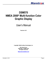
via a Maretron TMP100 Temperature Module. The wiring diagram appears in Figure 1 below. The diagram shows
a connection to channel #2, but connections to other channels are similar. Please note that the TP-IP-1 may be
connected only to channels #2, #3, #4, and #5. It may not be connected to channels #0 and #1.
1. The TP-IP-1 is packaged with a compression fitting for mounting the temperature probe to a liquid vessel.
Drill and tap a 1/4” NPT hole in the tank to be monitored where you want the probe to enter the tank.
(Alternatively, you may purchase a metric compression fitting instead).
2. Thread the male end of the compression fitting into the hole and tighten securely.
3. Insert the immersion probe into the compression fitting, and tighten the collar of the compression fitting to
achieve a snug, leak-proof fit.
4. The TP-IP-1 cable contains one red and one black wire. Connect the black wire to the appropriate Tx-
terminal on the TMP100 as shown in Figure 1 below.
5. Connect the red wire to the appropriate Tx+ terminal on the TMP100 as shown in Figure 1 below.
6. Use a DSM250 (firmware 1.3.8 or greater) or other Maretron display product capable of configuring the
TMP100 to configure the “Channel #x Source” to the type of temperature you are measuring.
7. Use a DSM250 (firmware 1.3.8 or greater) or other Maretron display product capable of configuring the
TMP100 to configure the “Channel #x Instance” to a number that is unique across the network for the
source you have selected. In other words, if you are measuring Live Well Temperature, there may be only
one channel on the network that measures Live Well Temperature that has an instance number of 0.
Number further Live Well Temperature channels as instance #1, #2, and so on.
8. If desired, use DSM250 (firmware 1.3.8 or greater) or other Maretron display product capable of
configuring the TMP100 to configure the “Channel #x Label” to a text string that allows you to identify the
particular temperature that is being measured by this probe. For example, if you have two tanks, you may
wish to label one of them “Port Live Well” and the other “Starboard Live Well”.
9. Using a Maretron DSM250 or Maretron N2KView, show the temperature with the source and instance you
have selected and verify that you see a valid temperature on the display.
Maretron, LLP
9014 N. 23
rd
Ave #10
Phoenix, AZ 85021
Telephone: (+1) 866-550-9100
E-mail: [email protected]
Web: http://www.maretron.com
1
2
5
4
3
6
7
8
9
10
11
12
T0+
T1-
TMP100 Screw Terminals
T0-
T1+
T2+
T2-
T3+
T3-
T4+
T4-
T5+
T5-
TP-IP-1 Immersion Probe
Red
Black
Figure 1 – Wiring Diagram
/