Page is loading ...

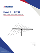
Model 3144
Log Periodic
Dipole Array Antenna
User Manual

ETS-Lindgren L.P. reserves the right to make changes to any product described
herein in order to improve function, design, or for any other reason. Nothing
contained herein shall constitute ETS-Lindgren L.P. assuming any liability
whatsoever arising out of the application or use of any product or circuit
described herein. ETS-Lindgren L.P. does not convey any license under its
patent rights or the rights of others.
© Copyright 1997–2010 by ETS-Lindgren L.P. All Rights Reserved. No part
of this document may be copied by any means without written permission
from ETS-Lindgren L.P.
Trademarks used in this document: The ETS-Lindgren logo is a trademark of
ETS-Lindgren L.P.
Revision Record
MANUAL 3144 LOG PERIODIC ANTENNA | Part # 399171, Rev. E
Revision Description Date
A–C Initial Release
Updates/edits
Updates/edits
January, 1997
D Updates/edits September, 2002
E Rebrand September, 2010
ii |

Table of Contents
Notes, Cautions, and Warnings ................................................ v
1.0 Introduction .......................................................................... 7
Optional Items ................................................................................................ 8
Support Rod ........................................................................................... 8
Tripod ..................................................................................................... 8
ETS-Lindgren Product Information Bulletin ................................................... 9
2.0 Maintenance ....................................................................... 11
Maintenance Recommendations ................................................................. 11
Annual Calibration ....................................................................................... 11
Service Procedures ..................................................................................... 11
3.0 Specifications ..................................................................... 13
Electrical Specifications ............................................................................... 13
Physical Specifications ................................................................................ 13
4.0 Mounting & Assembly ....................................................... 15
Mounting Instructions ................................................................................... 15
Using Included Mounting Adapters ...................................................... 15
Additional 4-TR Mounting Options ....................................................... 17
Additional 7-TR and Mast Mounting Options ....................................... 18
Additional 2x2 Boom Mounting Options .............................................. 19
Assembly Instructions .................................................................................. 20
5.0 Application ......................................................................... 21
6.0 Typical Data ........................................................................ 23
Model 3144 Antenna Factor ........................................................................ 23
Model 3144 Gain ......................................................................................... 23
Model 3144 VSWR ...................................................................................... 24
Model 3144 Half-Power Beamwidth ............................................................ 24
Model 3144 Forward Power 1M ................................................................... 25
Model 3144 Forward Power 3M ................................................................... 25
Appendix A: Warranty ............................................................. 27
| iii

This page intentionally left blank.
iv |

Notes, Cautions, and Warnings
Note: Denotes helpful information intended to
provide tips for better use of the product.
Caution: Denotes a hazard. Failure to follow
instructions could result in minor personal injury
and/or property damage. Included text gives proper
procedures.
Warning: Denotes a hazard. Failure to follow
instructions could result in SEVERE personal injury
and/or property damage. Included text gives proper
procedures.
See the ETS-Lindgren Product Information Bulletin for safety,
regulatory, and other product marking information.
| v

vi |
This page intentionally left blank.

1.0 Introduction
The ETS-Lindgren Model 3144
Log Periodic Dipole Array is a
linearly polarized, broadband
antenna designed to operate over the
frequency range of 80 MHz to 2 GHz.
The choice of scaling factors, the various diameters of each element, and the
center-to-center spacing of the booms are such that excellent VSWR
characteristics are obtained throughout the operating frequency range.
The precise design of the feed and the positioning of the elements on the boom
yield optimum phase relationship. This causes the active region, at any given
frequency, to propagate RF energy towards the smaller elements leaving the
elements behind it electrically dead.
The constant gain of the antenna yields an antenna factor which varies linearly
with frequency. The variation is smooth; therefore, accurate interpolation of
performance between specified frequency points is simple.
The Model 3144 is provided with an integral mount and the necessary
attachments to mount the antenna to either a tripod (with a 1/4–20 threaded
mount) or an ETS-Lindgren antenna mast. For the variety of mounting options
available for the Model 3144, see Mounting & Assembly on page
15.
Each Model 3144 is individually calibrated at one meter per SAE ARP 958 and at
three and 10 meters per ANSI C63.5. Actual antenna factors and a signed
Certificate of Calibration Conformance are included.
Introduction | 7

Optional Items
SUPPORT ROD
Antenna mount with insert drilled to accept ETS-Lindgren or other tripods with
standard 1/4–20 threads.
TRIPOD
ETS-Lindgren offers the following non-metallic, non-reflective tripods for use at
both indoor and outdoor EMC test sites.
• 4-TR Tripod—Constructed of linen
phenolic and delrin, designed with an
adjustable center post for precise height
adjustments. Maximum height is 2.0 m
(80.0 in), and minimum height is 94 cm
(37.0 in). This tripod can support up to
an 11.8 kg (26.0 lb) load.
8 | Introduction

• 7-TR Tripod—Constructed of PVC and
fiberglass components, providing
increased stability for physically large
antennas. The unique design allows for
quick assembly, disassembly, and
convenient storage. Allows several
different configurations, including options
for manual or pneumatic polarization.
Quick height adjustment and locking
wheels provide ease of use during
testing. Maximum height is 2.17 m
(85.8 in), with a minimum height of 0.8 m
(31.8 in). This tripod can support a
13.5 kg (30 lb) load.
ETS-Lindgren Product Information Bulletin
See the ETS-Lindgren Product Information Bulletin included with your shipment
for the following:
• Warranty information
• Safety, regulatory, and other product marking information
• Steps to receive your shipment
• Steps to return a component for service
• ETS-Lindgren calibration service
• ETS-Lindgren contact information
Introduction | 9

This page intentionally left blank.
10 | Introduction

2.0 Maintenance
Before performing any maintenance,
follow the safety information in the
ETS-Lindgren Product Information
Bulletin included with your shipment.
Maintenance of the Model 3144 is limited
to external components such as cables
or connectors.
If you have any questions concerning
maintenance, contact ETS-Lindgren
Customer Service.
WARRANTY
Maintenance Recommendations
If the Model 3144 Log Periodic Dipole Array Antenna is used outdoors, periodic
removal of the antenna cable connection and cleaning of any corrosion may be
needed to maintain accuracy of the measurements. An inspection to determine
the need for cleaning should be made at least every six months. More frequent
inspection may be needed depending on the atmosphere and the environment in
which the antenna is used.
Annual Calibration
See the Product Information Bulletin included with your shipment for information
on ETS-Lindgren calibration services.
Service Procedures
For the steps to return a system or system component to ETS-Lindgren for
service, see the Product Information Bulletin included with your shipment.
Maintenance | 11

This page intentionally left blank.
12 | Maintenance

3.0 Specifications
Electrical Specifications
Frequency Range: 80 MHz–2 GHz
Input Impedance: 50 Ohms
VSWR: Average: 1.2:1
Maximum: 2.0:1
CW Power: 1000 W
Symmetry: +/– 0.5 dB
Connector: Type N Female
Physical Specifications
Height: 6.4 cm (2.5 in)
Width: 213.4 cm (84.0 in)
Depth: 167.6 cm (66.0 in)
Weight: 4.3 kg (9.5 lb)
Specifications | 13

This page intentionally left blank.
14 | Specifications

4.0 Mounting & Assembly
The Model 3144 antennas are precision
measurement devices. Handle your antenna
with care.
Mount the Model 3144 Log Periodic Dipole Array Antenna first, and
then attach the elements to the antenna.
Mounting Instructions
USING INCLUDED MOUNTING ADAPTERS
The Model 3144 ships with these mounting adapters:
• 100989 Polarizing Mounting
Adapter with 7/8–14 thread
receptacle
If you need to convert the polarizing
adapter to a 1/4–20 receptacle,
insert the 1/4–20 thread insert into
the polarizing adapter
• 105861B 1/4–20 Thread Insert
Mounting & Assembly | 15

To attach the included adapters to the Model 3144:
1. If required, insert the 1/4–20 thread insert into the polarizing adapter.
2. Remove the mounting knob from the mounting bracket on the antenna.
3. Slide the polarizing adapter into the mounting bracket by placing the
polarizing adapter placed between the shoulders of the mounting
bracket.
16 | Mounting & Assembly

Do not cross thread or permanent damage to the adapter could occur.
4. Thread the mounting knob through the mounting bracket, then through
the polarizing adapter, and finally through the hex nut.
5. Tighten the mounting knob to secure the antenna.
6. Attach the polarizing adapter and antenna to tripod or tower, as
required.
ADDITIONAL 4-TR MOUNTING OPTIONS
Following are additional options for mounting the Model 3144 onto an
ETS-Lindgren 4-TR tripod. Contact the ETS-Lindgren Sales Department for
information on ordering optional mounting hardware.
Mounting & Assembly | 17

ADDITIONAL 7-TR AND MAST MOUNTING OPTIONS
Following are options for mounting the Model 3144 onto an ETS-Lindgren 7-TR
Tripod or mast. Contact the ETS-Lindgren Sales Department for information on
ordering optional mounting hardware.
Mast refers to 2070 Series, 2075, and 2175 Antenna Towers.
7-TR refers to 109042 and 108983 booms:
• 109042 boom—Straight boom; for general antenna mounting on a
7-TR.
• 108983 boom—Offset boom; for general antenna mounting on a
7-TR with pneumatic or manual polarization; can also be used to
mount stinger-type antennas.
18 | Mounting & Assembly

ADDITIONAL 2X2 BOOM MOUNTING OPTIONS
Following are additional options for mounting the Model 3144 onto a 2x2 boom.
Contact the ETS-Lindgren Sales Department for information on ordering optional
mounting hardware.
2x2 boom refers to a typical 2-inch by 2-inch boom.
Mounting & Assembly | 19

Assembly Instructions
To facilitate transport, the Model 3144 is shipped with the five longest elements
on each side removed. After you mount the antenna, follow these assembly
steps:
• Do not cross thread or permanent damage to the antenna and
element could occur.
• Do not overtighten or use excessive force or permanent damage
to the antenna and element could occur.
1. Carefully thread one of the numbered elements into the corresponding
numbered receptacle.
2. Thread the element until it is finger tight.
3. Repeat these steps until all of the numbered elements are mounted.
20 | Mounting & Assembly
/