Land Pride ZT3 User manual

Type
User manual

This manual is also suitable for

Land Pride ZT3 Series: Tackle your mowing tasks with enhanced visibility and safety. This comprehensive safety kit includes a beacon light for increased visibility, a slow-moving vehicle (SMV) sign for added safety on the road, and a wire harness for seamless integration with your ZT360 or ZT372 Zero Turn Mower. The kit is designed for easy installation and comes with all the necessary hardware and detailed instructions. Ensure your mowing operations are safe and compliant with this essential accessory.

Land Pride ZT3 Series: Tackle your mowing tasks with enhanced visibility and safety. This comprehensive safety kit includes a beacon light for increased visibility, a slow-moving vehicle (SMV) sign for added safety on the road, and a wire harness for seamless integration with your ZT360 or ZT372 Zero Turn Mower. The kit is designed for easy installation and comes with all the necessary hardware and detailed instructions. Ensure your mowing operations are safe and compliant with this essential accessory.

1
© Copyright 2013 Printed
Before You Start
A separate Parts Manual for your Zero Turn Mower is
available free of charge at www.landpride.com or can be
purchased from your nearest Land Pride dealer. Have
the model and serial number of your Zero Turn Mower
handy when placing an order.
Manual Part Numbers:
ZT360 & ZT372
Operator’s Manual . . . . . . . . . . . . . . . . 357-610M
Parts Manual . . . . . . . . . . . . . . . . . . . . . 357-610P
General Information
Your Light Kit is exclusively designed for your Land Pride
model ZT360 or ZT372 Zero Turn Mower. Please read
these installation instructions and your mower’s
Operator’s Manual thoroughly before beginning.
Especially read information relating to safety concerns.
Tools required:
Safety Glasses & Work Gloves
9/32" & 3/8" box end or open end wrenches
Phillips screwdriver
Standard blade screwdriver
T25 Torx Screwdriver
Assembly Instructions
These assembly instructions apply to the following Light
Kit Accessory listed below:
357-639A ZT3 SAFETY LIGHT AND SIGN KIT
A detailed listing of parts for this accessory kit is provided
on page 5. Use this list as a checklist to inventory parts
received. Please contact your local Land Pride dealer for
any missing hardware.
IMPORTANT: Before you begin, read these
instructions and check to be sure all parts and tools
are accounted for. Please retain these installation
instructions for future reference and parts ordering
information.
Further Assistance
Your dealer wants you to be satisfied with your new Light
Kit. If for any reason you do not understand any part of
this manual or are not satisfied with the service received,
the following actions are suggested:
1. Discuss the matter with your dealership service
manager making sure that person is aware of any
problems you may have and has had the opportunity
to assist you.
2. If you are still not satisfied, seek out the owner or
general manager of the dealership, explain the
problem, and request assistance.
3. For further assistance write to:
Land Pride Service Department
1525 East North Street
P.O. Box 5060
Salina, Ks. 67402-5060
E-mail address
Initial Preparations
1. Disengage blades, park mower on a flat surface,
move control levers fully out, and set park brake.
2. Turn off engine and remove ignition key.
3. Rotate seat platform fully up.
Refer to Figure 1:
4. Disconnect negative ground wire (black wire) from
the battery’s negative post ( - ). Place ground wire in
a location where it cannot touch the battery posts.
Remove Ground Wire From Battery
Figure 1
Negative Post (-)
Negative (-) Black
Ground Wire
Positive Post (+)
Located Under
Red Cover
35589
Safety Light & Sign Kit
Assembly Instructions
7/15/13
Manual No. 357-640M
For ZT360 & ZT372 Zero Turn Mowers
2
Manual No. 357-640M 7/15/13
Land Pride
Further Assistance
Bumper Requirements
ZT3 Series mowers with serial number __________+ are
shipped from the factory with mounting holes for this kit
and do not require any modifications.
The bumper and Land Pride decal on ZT3 Series mowers
with serial number _________- will need to be replaced
or new holes will need to be drilled in the existing bumper.
When replacing bumper, order bumper part number
358-366D and Land Pride decal part number 848-161C
from your nearest Land Pride dealer.
Refer to Figure 2:
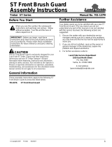
If mounting bracket holes are to be drilled in rear
bumper, then use mounting bracket (#1) as a template to
locate and drill four 9/32" holes. Replace carriage
bolts (#4) with four new 1/4"-20 x 3/4" GR5 hex head bolts
(hex head bolts to be supplied by customer).
Refer to Figure 4 on page 3:
If cable tie holes are to be drilled in rear bumper to attach
beacon harness (#13) with cable ties (#12), then locate
and drill four 9/32" holes along the left top edge of rear
bumper in the locations shown.
Safety Beacon Light & SMV Sign
Refer to Figure 2:
1. Attach mounting bracket (#1) on the inside of rear
bumper with 1/4"-20 x 3/4" GR5 carriage bolts (#4),
flat washers (#9), spring lock washers (#8), and hex
nuts (#5). Tighten hex nuts to the 8 ft-lbs.
2. Attach SMV sign (#10) to mounting bracket (#1) with
1/4"-20 x 3/4" pan head screws (#2), flat
washers (#9), spring lock washers (#8), and hex
nuts (#5). Tighten hex nuts to the 5.6 ft-lbs.
3. Attach amber beacon light (#11) to mounting
bracket (#1) with #10-24 x 2" pan head machine
screws (#3), internal star washers (#7), and hex
nuts (#6). Tighten hex nuts.
Beacon Wire Harness
Refer to Figure 3:
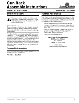
1. Attach connector “B” on end of beacon wire
harness (#13) to beacon light connector “A”.
2. Secure beacon wire connector “A” and beacon wire
harness (#13) to upper and lower slits in mounting
bracket (#1) with cable ties (#12).
NOTE: See “Bumper Requirements” above
before attaching mounting bracket (#1) to rear
bumper.
NOTE: For good appearance, install mounting
bracket (#1) on the inside of the rear bumper.
NOTE: Do not draw cable ties up tight until after
wire harness (#13) is fully assembled.
Attach Safety Beacon Light & SMV Sign
Figure 2
Attach Wire Harness to Mounting Bracket
Figure 3
35595
Rear Bumper
B
A
1
12
13
35590
3
7/15/13
Manual No. 357-640M
Further Assistance
Land Pride
Attach Wire Harness to Rear Bumper
Figure 4
Refer to Figure 4:
3. Attach beacon wire harness (#13) on the inside of
the rear bumper with cable ties (#12) in the four
locations shown.
4. Insert beacon wire harness (#13) through hole “C” in
engine fire wall.
Refer to Figure 5:
5. Thread beacon wire harness (#13) beneath seat
spring latch assembly and behind existing looms.
6. Attach beacon wire harness (#13) to existing loom
with cable tie (#12) as shown.
Refer to Figure 6:
7. Route beacon wire harness (#13) behind hydraulic
expansion tank hose “D” located on the right-hand
side.
8. Continue to route beacon wire harness (#13) through
opening “E” on right-hand side of mower frame and
up through opening in console well.
12
C
12
12
13
35591
Rear Bumper
NOTE: See “Bumper Requirements” on page 2
before mounting wire harness (#13) to rear bumper.
Attach Wire Harness Beneath Spring Latch Assembly
Figure 5
Route Wire Harness Behind Right-hand Expansion Tank
Figure 6
12
13
35592
13
13
35593
13
E
D
4
Manual No. 357-640M 7/15/13
Land Pride
Further Assistance
Beacon Harness Connected to Hour Meter Spades
Figure 8
13
35594
A
B
C
Positive Spade (+)
E
Choke Cable
D
Throttle
Cable
F
Negative Spade (-)
Hour Meter
Attach Beacon Wire Harness To Hour Meter
Refer to Figure 7:
1. Remove two Torx screws “F” securing console panel.
2. Lift console panel up and locate hole in bottom of
console well.
3. Pull wire harness (#13) up through hole in bottom of
console well.
4. Plastic tie beacon harness to main loom inside of
cavity.
Hour Meter Connection
Refer to Figure 8:
1. Disconnect gray wire female terminal “A” from hour
meter positive (+) spade and then reconnect
terminal “A” to white wire male terminal “B” on end of
beacon harness (#13) as shown.
2. Connect white female terminal “C” on end of beacon
harness (#13) to the hour meter’s positive (+) spade.
3. Disconnect black wire female terminal “D” from hour
meter negative (-) spade and then reconnect
terminal “D” to black male terminal “E” on end of
beacon harness (#13) as shown.
4. Connect black female terminal “F” on end of beacon
harness (#13) to negative (-) spade on hour meter.
Final Assembly
Refer to Figure 1 on page 2:
1. Add additional cable ties (#12) throughout the length
of the beacon wire harness (#13) as needed.
IMPORTANT: Do not tie beacon harness (#13) to
throttle cable or choke cable. Tying harness to either
cable will limit the cable’s operation.
Console Panel
Figure 7
2. Make final adjustments to beacon harness (#13) and
then draw all cable ties (#12) up tight.
3. Reconnect ground cable to negative battery post.
Refer to Figure 8:
4. Check hook-up of beacon harness (#13) buy turning
ignition switch on without starting engine. Beacon
light should be blinking. If light does not blink,
reverse hour meter connections “C” & “F” and retest
beacon light.
Refer to Figure 7:
5. Replace console panel and tighten screws.
Hour Meter
Blade Engagement
Switch
Ignition
Switch
F
F
24961
Throttle Lever
Choke Knob
7/15/13
Manual No. 357-640M
5
Item Part No. Part Description Qty
Land Pride
Listing of Parts
1. 358-398D ZT BEACON AND SMV MNT . . . . . . . . . . . . . . . . . . . . . . . . . . . . . . . . . . . . . . . . 1
2. 801-005C SCREW PAN HD 1/4-20 X 3/4. . . . . . . . . . . . . . . . . . . . . . . . . . . . . . . . . . . . . . . . 2
3. 801-196C PHMS #10-24X2 SS . . . . . . . . . . . . . . . . . . . . . . . . . . . . . . . . . . . . . . . . . . . . . . . 3
4. 802-002C RHSNB 1/4-20X3/4 GR5 . . . . . . . . . . . . . . . . . . . . . . . . . . . . . . . . . . . . . . . . . . . . 4
5. 803-006C NUT HEX 1/4-20 PLT. . . . . . . . . . . . . . . . . . . . . . . . . . . . . . . . . . . . . . . . . . . . . . . 6
6. 803-269C NUT HEX 10-32 PLT . . . . . . . . . . . . . . . . . . . . . . . . . . . . . . . . . . . . . . . . . . . . . . . 3
7. 804-004C WASHER INTERNAL STAR #10 PLT. . . . . . . . . . . . . . . . . . . . . . . . . . . . . . . . . . . 3
8. 804-006C WASHER LOCK SPRING 1/4 PLT. . . . . . . . . . . . . . . . . . . . . . . . . . . . . . . . . . . . . 6
9. 804-007C WASHER FLAT 1/4 SAE PLT. . . . . . . . . . . . . . . . . . . . . . . . . . . . . . . . . . . . . . . . . 6
10. 818-055C DECAL SLOW MOVING-GALV. BACKED . . . . . . . . . . . . . . . . . . . . . . . . . . . . . . . 1
11. 833-563C BEACON LIGHT AMBER. . . . . . . . . . . . . . . . . . . . . . . . . . . . . . . . . . . . . . . . . . . . 1
12. 800-060C CABLE TIE .19X14.25 3DIA 50LB. . . . . . . . . . . . . . . . . . . . . . . . . . . . . . . . . . . . 10
13. 833-651C ZT BEACON WIRE HARNESS . . . . . . . . . . . . . . . . . . . . . . . . . . . . . . . . . . . . . . . 1
Kit No. 357-639A ZT3 SAFETY LIGHT AND SIGN KIT
35597
Corporate Office: P.O. Box 5060
Salina, Kansas 67402-5060 USA
www.landpride.com
  • Page 1 1
  • Page 2 2
  • Page 3 3
  • Page 4 4
  • Page 5 5
  • Page 6 6

Land Pride ZT3 User manual

Type
User manual
This manual is also suitable for

Land Pride ZT3 Series: Tackle your mowing tasks with enhanced visibility and safety. This comprehensive safety kit includes a beacon light for increased visibility, a slow-moving vehicle (SMV) sign for added safety on the road, and a wire harness for seamless integration with your ZT360 or ZT372 Zero Turn Mower. The kit is designed for easy installation and comes with all the necessary hardware and detailed instructions. Ensure your mowing operations are safe and compliant with this essential accessory.

Ask a question and I''ll find the answer in the document

Finding information in a document is now easier with AI