Page is loading ...


Servicing North America:
USA: One Omega Drive, Box 4047
ISO 9001 Certified Stamford, CT 06907-0047
Tel: (203) 359-1660 FAX: (203) 359-7700
e-mail: [email protected]
Canada: 976 Bergar
Laval (Quebec) H7L 5A1
Tel: (514) 856-6928 FAX: (514) 856-6886
e-mail: [email protected]
For immediate technical or application assistance:
USA and Canada: Sales Service: 1-800-826-6342 / 1-800-TC-OMEGA
SM
Customer Service: 1-800-622-2378 / 1-800-622-BEST
SM
Engineering Service: 1-800-872-9436 / 1-800-USA-WHEN
SM
TELEX: 996404 EASYLINK: 62968934 CABLE: OMEGA
Mexico and
Latin America:
Tel: (95) 800-TC-OMEGA
SM
FAX: (95) 203-359-7807
En Espan÷ol: (203) 359-7803 e-mail: [email protected]
Servicing Europe:
Benelux: Postbus 8034, 1180 LA Amstelveen, The Netherlands
Tel: (31) 20 6418405 FAX: (31) 20 6434643
Toll Free in Benelux: 06 0993344
e-mail: [email protected]
Czech Republic: ul. Rude armady 1868, 733 01 Kavrine-Hranice,
Czech Republic
Tel: 420 (69) 6311627 FAX: 420 (69) 6311114
e-mail: [email protected]
France: 9, rue Denis Papin, 78190 Trappes
Tel: (33) 130-621-400 FAX: (33) 130-699-120
Toll Free in France: 0800-4-06342
e-mail: [email protected]
Germany/Austria: Daimlerstrasse 26, D-75392 Deckenpfronn, Germany
Tel: 49 (07056) 3017 FAX: 49 (07056) 8540
Toll Free in Germany: 0130 11 21 66
e-mail: [email protected]
United Kingdom: 25 Swannington Road, P.O. Box 7, Omega Drive,
ISO 9002 Certified Broughton Astley, Leicestershire, Irlam, Manchester,
LE9 6TU, England M44 5EX, England
Tel: 44 (1455) 285520 Tel: 44 (161) 777-6611
FAX: 44 (1455) 283912 FAX: 44 (161) 777-6622
Toll Free in England: 0800-488-488
e-mail: [email protected]
OMEGAnet
SM
On-Line Service Internet e-mail
http://www.omega.com [email protected]
It is the policy of OMEGA to comply with all worldwide safety and EMC/EMI regulations that
apply. OMEGA is constantly pursuing certification of its products to the European New Approach
Directives. OMEGA will add the CE mark to every appropriate device upon certification.
The information contained in this document is believed to be correct but OMEGA Engineering, Inc. accepts
no liability for any errors it contains, and reserves the right to alter specifications without notice.
WARNING: These products are not designed for use in, and should not be used for, patient connected applications.

Quick Start. . . . . . . . . . . . . . . . . . . . . . . . . . . . . . . . . . . . . . . . Page ii
Introduction
Electrode Connector Inputs . . . . . . . . . . . . . . . . . . . . . . . . . . . . 1
Batteries . . . . . . . . . . . . . . . . . . . . . . . . . . . . . . . . . . . . . . . . . . . . 1
LCD Display. . . . . . . . . . . . . . . . . . . . . . . . . . . . . . . . . . . . . . . . . 2
Function Keys. . . . . . . . . . . . . . . . . . . . . . . . . . . . . . . . . . . . . . . . 3
Electrodes
Preparing pH and Ion Selective Electrodes . . . . . . . . . . . . . . . . 4
Preparing Conductivity Cells. . . . . . . . . . . . . . . . . . . . . . . . . . . . 4
Connecting Electrodes . . . . . . . . . . . . . . . . . . . . . . . . . . . . . . . . 5
Using and Storing Electrodes. . . . . . . . . . . . . . . . . . . . . . . . . . . . 6
pH Electrodes. . . . . . . . . . . . . . . . . . . . . . . . . . . . . . . . . . . . . . 6
Solid-State FET Electrodes . . . . . . . . . . . . . . . . . . . . . . . . . . . . 6
Ion Selective Electrodes . . . . . . . . . . . . . . . . . . . . . . . . . . . . . 7
Conductivity Cells . . . . . . . . . . . . . . . . . . . . . . . . . . . . . . . . . . 7
Meter Operation
Setup Menu . . . . . . . . . . . . . . . . . . . . . . . . . . . . . . . . . . . . . . . . . 8
Standardizing and Measuring pH
pH StandardizatIon Menu . . . . . . . . . . . . . . . . . . . . . . . . . . . . . . 9
Standardizing and Measuring pH . . . . . . . . . . . . . . . . . . . . . . . 10
Clearing Buffers . . . . . . . . . . . . . . . . . . . . . . . . . . . . . . . . . . . . . 11
Standardizing and Measuring mV
Relative mV Standardization Menu . . . . . . . . . . . . . . . . . . . . . 12
Clearing Relative mV Mode . . . . . . . . . . . . . . . . . . . . . . . . . . . 12
Standardizing and Measuring Ion
Ion Standardization Menu. . . . . . . . . . . . . . . . . . . . . . . . . . . . . 13
Standardizing and Measuring Ion. . . . . . . . . . . . . . . . . . . . . . . 14
Clearing Standards . . . . . . . . . . . . . . . . . . . . . . . . . . . . . . . . . . 14
Standardizing and Measuring Conductivity
Conductivity Standardization Menu. . . . . . . . . . . . . . . . . . . . . 15
Standardizing and Measuring Conductivity,
Salinity,Resistivity or TDS. . . . . . . . . . . . . . . . . . . . . . . . . . . . . . . 16
Clearing Standards . . . . . . . . . . . . . . . . . . . . . . . . . . . . . . . . . . 17
Temperature Compensation. . . . . . . . . . . . . . . . . . . . . . . . . . . 17
Determining Temperature Coefficients. . . . . . . . . . . . . . . . . . . 18
Datalogging . . . . . . . . . . . . . . . . . . . . . . . . . . . . . . . . . . . . . . . . . . 19
Appendix A: Power Station and Docking Station . . . . . . . . . . . . . 20
Appendix B: Error Conditions and Troubleshooting . . . . . . . . . . . 22
Appendix C: Basic pH Theory . . . . . . . . . . . . . . . . . . . . . . . . . . . . 25
Appendix D: Ion Selective Electrode Theory . . . . . . . . . . . . . . . . 26
Appendix E: Conductivity Theory . . . . . . . . . . . . . . . . . . . . . . . . . 27
Appendix F: Determining Isopotential Point . . . . . . . . . . . . . . . . . 28
Appendix G: Meter Specifications . . . . . . . . . . . . . . . . . . . . . . . . 30
Maintenance and Cleaning . . . . . . . . . . . . . . . . . . . . . . . . . . . . . 31
i

The following quickly steps you through meter operation.For
detailed instructions on each step,refer to the page(s) indicated.
Step Description Page
1. Install Batteries Install four AA alkaline batteries 1
into the rear battery compartment.
2. Connect Install electrode in the appropriate 5
Electrode connector input on top of the meter.
3. Turn Meter On Press On/Off. 3
4. Select Channel Make sure that the channel selected, 3
A (Twist-Lock input) or B (BNC input),
matches the electrode connection.
Press channel and select.Note: If no
electrode is connected to channel A
Twist-Lock input,only channel B is
allowed.
5.Set Mode For the channel A Twist-Lock input, 3
the meter automatically recognizes
the electrode connected,and selects
the appropriate modes.For channel B
BNC input,any allowed mode can be
selected.Press mode and select.
6. Standardize Immerse the electrode into a buffer or 9 (pH)
standard and stir.Press std (standard- 13 (ion)
ize) and follow the prompts.Repeat 15 (Conductivity)
this step to enter buffers or standards.
5. Print Press Print to send the measurement 19
to the internal datalog and out to a
printer/computer ( if using the Docking
Station).
Warning: Use of this product in a manner not specified by the
manufacturer may impair any safety protection provid-
ed by the equipment.
!

This manual explains the operation of
PHH-925 and PHH-950 meters for obtain-
ing pH,mV,ion and conductivity (PHH-
950) measurements.Before beginning,we
recommend that you become familiar
with the various features of your meter:
Electrode Connector Inputs
Twist-Lock: Used for attaching pH/ATC,
FET pH/ATC,conductivity/ATC cells or
ATC (temperature) electrodes with the
waterproof Twist-Lock connector.
BNC: Used for attaching pH,ORP,or ISE
electrodes with BNC connector.
Reference: Used for attaching a sepa-
rate reference probe.
Batteries
The meter requires four AA alkaline bat-
teries (unless used with the optional
Power or Docking Station).To install bat-
teries,slide the compartment cover open
by pressing in and down where indicat-
ed.Position the batteries according to
the directional markings and insert.Slide
the cover closed.
Note: Nickel-cadmium rechargeable
batteries can be used,but their
operating life is half that of alkaline
cells, and they cannot be
recharged in the meter.
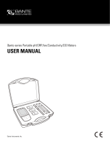
LCD Display
BNC
Reference Twist-Lock
1

Note: Not all of the following will dis-
play at the same time.
Temperature: The meter displays
the measured temperature when
an electrode with ATC or separate
temperature probe is attached.
Shows M when a manually entered
temperature is being used.
Result: Current measurement.
BAT: Indicates that the meter has
10% of battery life remaining
(approximately 4 hours),or AC
indicates that the meter is con-
nected to the Docking or Power
Station.
Channel: Indicates result is from A
(Twist-Lock input) or B (BNC input).
Manual Temperature: M indicates
that measurement is using a manu-
ally entered temperature in place
of the automatic temperature.(See
page 13).
Date: The meter displays the cur-
rent date,either in mm/dd/yy or
dd/mm/yy format.
Buffers/Standards: Shows individual
buffers or standards that have
been entered.
Stability symbols: S indicates the
reading is stable,U indicates an
unstable reading.
Mode: Indicates the meter is in pH,
mV,ion,rel mV,conductivity,resistivi-
ty,salinity or TDS mode.
Time: Displays the current time in
either 12 hour AM/PM or 24 hour
format.
Function Keys
A
M 25.0°C
BAT
7.000
A M pH
4.00
7.00
10.00
1/24/97 11:52 AM
S
G
A
I
F
D
J
C
B
E
H
B
C
D
E
F
G
H
I
J
Single Channel Display
21.3°C
7.000
A pH
1.00
B M mg/L F-
1/24/97 11:53 AM
Dual Channel Display
S
S

mode: Selects the mode (pH,mV,ISE
temperature,conductivity,resistivi-
ty,salinity,or TDS) to use for the
currently selected channel (elec-
trode input).
std: Initiates standardization process
for the currently selected mode to
enter pH buffers,ion standards or
conductivity standards.
channel: Selects the channel(s) (electrode
inputs) to display.
slope: Displays buffers or standards and
calibration data in slope display.
Press data to see the time and
date for each calibration point.
print: Outputs the current result or cali-
bration data to the Docking
Station RS232 interface and the
internal datalog.
setup: Calls the setup menu (see Setup).
Up/Down Scrolls when viewing stored data
Arrows: and sets the display contrast.
data: Enters the datalogging menu
(see Datalogging).
enter: Accepts numeric values,menu
selections or pending operations.
on/off: Turns the meter on and off.
clear: Clears an incorrect number entry
or cancels the current operation.
Numeric Enters numbers for menu selec-
Keypad: tion,standard entry and other
operations.
+ Enters a negative value.
•: Enters a decimal point.
10
X
: Enters the exponential part of a
number.
1
4
7
2
5
8
3
6
9
0
+
.
10
x
mode
std channel
slope
print setup
data
enter
on/off
clear
3

Electrodes
The meter allows you to use a variety of
glass membrane (“glass”) pH/ATC elec-
trodes,ion selective electrodes,the Field
Effect Transistor (FET) Solid-State pH/ATC
electrode (PHH-925 only),temperature
(ATC) probes,Conductivity/ATC cells (AP50
only),combination electrodes using a BNC
connector,or separate electrode pairs with
BNC connector and reference pin.The
glass pH,FET pH and conductivity cells with
Twist-Lock connector are automatically
detected and identified by the meter.
Preparing pH and Ion Selective Electrodes
Remove the protective end cover or the
soaker bottle from the electrode.Before
first using your pH electrode or whenever
the electrode is dry,soak it several hours in
an electrode filling or storage solution (4
Molar KCl solution) or in a buffer for pH
electrodes.Store and condition ISE’s in the
recommended solutions.
Preparing Conductivity Cells
Remove the protective end cover from the
cell.Rinse the cell with deionized or de-
mineralized water.
To measure Use channel (connector)
pH A (Twist-Lock)
or
B (BNC)
ORP (mV) B (BNC)
FET pH A (Twist-Lock)
ISE B (BNC & Reference)
Conductivity A (Twist-Lock)
pH & ISE A (Twist-Lock pH)
and
B (BNC ISE)
pH & Conductivity A (Twist-Lock Cond.)
and
B (BNC pH)

Connecting Electrodes
Note: If you install an electrode with a
Twist-Lock connector,the meter
automatically senses it and selects
the appropriate mode and stan-
dardize menus for that type of
electrode.
Glass pH/ATC, FET pH/ATC electrode, con-
ductivity/ATC cell or ATC Probe (with
Twist-Lock connector):
Connect the electrode to the Twist-Lock
input located at the top of the meter. Line
up the white arrow and line on the elec-
trode’s Twist-Lock connector and push
until it locks in place.To disconnect,twist
the connector ring in the arrow direction
and pull apart.
pH, ORP or ISE electrode (with BNC con-
nector):
Connect the electrode to the BNC input
located at the top of the meter. Push in
and rotate the electrode’s BNC connec-
tor until it locks in place.To disconnect,
twist the BNC connector in the opposite
direction and pull.
Electrode Pair Using a Reference
Electrode (with Reference Pin Plug):
Connect the indicating electrode to the
BNC input.Connect the reference elec-
trode to the Reference input.Push the
electrode’s tip pin plug into the input to
connect and pull out to disconnect.
BNC
Input
Twist Lock
Input
5
BNC
Input
Reference
Input

Using and Storing Electrodes
pH Electrodes
Provide moderate stirring for faster
electrode response.
Rinse the electrode between each
measurement with a portion of the
next sample or buffer to be measured,
or with deionized or distilled water.
Keep glass electrodes wet when not
being used by moistening the cotton in
their end covers with electrode filling
solution and storing them with end
covers on,or by placing in their stor-
age vials.
Keeping glass electrodes “wet”will
improve their performance.In the lab,
store electrodes in electrode filling solu-
tion or storage solution (4M KCl).For
electrodes used in field applications,
occasionally leave them in solutions for
several hours.
Solid-State FET Electrode
The model PHH-925 allows use of both
standard glass pH/ATC and Solid-State
FET (Field Effect Transistor) pH/ATC elec-
trodes.The meter can store a calibra-
tion for both types of electrodes.Plug
the FET electrode into the Twist-lock
input. Allow the FET about 2 minutes to
warm up and stabilize when first con-
nected.The FET electrode can be
stored dry or in electrode storage solu-
tion.If the FET electrode remains con-
nected to the meter (and batteries are
in the meter),further warm up is not
necessary.

Ion Selective Electrodes
Add proper amount of Ionic Strength
Adjuster (ISA) to all standards and
samples.
Provide moderate stirring for faster
electrode response.
Rinse the electrode(s) between each
measurement with a portion of the
next sample or standard to be mea-
sured,or with deionized or distilled
water.
In the lab, follow the instruction sheets
for the individual electrode.Store as
recommended.
Conductivity Cells
Rinse the cell between each measure-
ment with a portion of the next sample
or standard to be measured.
Immerse the cell fully into the standard
or sample to be measured,lift the cell
to allow the solution inside the cell to
drain,and immerse the cell again.
Repeat three times.
Stir briefly and tap the cell against the
container bottom to dislodge air
bubbles.
Clean any deposits from the cell body
by rinsing with deionized water and
store dry.
7

Setup Menu
Press setup to access the menu options.
1. Check battery - Indicates the bat-
tery power remaining.
2. Set sleep mode - Enter the time in
minutes before the meter auto-
matically turns itself off (“sleeps”) if
no keystrokes have been pressed.
Enter a value of 0 to keep the
meter on continuously.The maxi-
mum time allowed is 999 minutes.
3. Set sample ID# - Select a starting
value for the sample ID number.
Sample measurements will then
be identified by sequential sample
ID numbers.Each time the print
key is pressed the sample number
will be incremented.
4. Set time and date - Enter time and
format,and date and format.
5. Signal averaging - Set the meter
to very slow (10 readings),slow
(8),medium (6),fast (4) and very
fast (2).The meter places each
new reading into a moving win-
dow,from which it calculates the
average (displayed) and standard
deviation (for stability determina-
tion).
6. Manual temperature - Enter a tem-
perature to be used in the
absence of an ATC probe or with
manual temperature override.
7. Set contrast - Adjust the display
contrast.
8. Printer baud rate - Select the baud
rate for the RS232
input/output.
Pressing a number key causes that menu
selection to be chosen or that operation
to be executed.
Setup Menu
1 - Check battery
2 - Set sleep mode
3 - Set sample ID#
4 - Set time and date
5 - Signal averaging
6 - Manual temperature
7 - Set contrast
8 - Printer baud rate

pH Standardization Menu
Press mode and select 1 – pH. Press std
and the standardize pH menu appears:
1. Enter a buffer - Allows you to add
a new buffer or update an existing
buffer. Follow the prompts.
2. Clear buffers - Clears all buffers
currently stored.
3. Select buffer set - There are five auto-
recognition buffer sets,one custom
set and manual entry
available.For some buffer sets the
meter will ask for the nominal refer-
ence temperature for the buffers set
(the temperature at which the
buffers are at their nominal values;
e.g.,7.000 at 25°C).
Auto-recognition buffer sets - The
five buffer sets are automatically
recognized and temperature cor-
rected for the variation of buffer
pH with temperature.
Custom buffers - Allows you to
enter up to five custom buffers
(each at least two pH units
apart),with no temperature com-
pensation.
Manual entry - Allows you to enter
any buffer value.
4. Enter slope - Allows you to enter a
known slope to be used by the meter
with a single-point standardization.
The normal default slope is 59.16
mV/pH.The meter allows between 80
and 120 % efficiency to be entered.
5. Temperature source - Allows the
meter to be set to use the ATC if pre-
sent (Auto) or use a manual tempera-
ture override (Manual).
6. Set isopoint - Allows you to enter in an
isopotential point (See Appendix F).
7. Resolution - Allows pH readings to be
set to 0.1,0.01,or 0.001 pH units.
9
Auto-recognition
Buffer Sets
• 2,4,7,10,12
• NIST 1.68,4.01,6.86,
9.18,12.46
• 1,3,6, 8,10,13
• DIN 1.09,3.06,4.64,
6.79,9.23,12.75
• 1,4,7, 10,13
• Custom buffers
Standardize pH
Channel A
1 - Enter a buffer
2 - Clear buffers
3 - Select buffer set
4 - Enter slope
5 - Temperature
source
6 - Set isopoint
7 - Resolution
Note: During auto-
matic calibration,the
meter allows pH
electrodes with 90 to
105% efficiency to
be used.

Standardizing and Measuring pH
1. Immerse the electrode in a buffer
and stir moderately.The meter dis-
plays the current pH measurement.
2. Press std, then press 1–Enter a buffer.
3. Follow the prompts on the display.
4. The meter automatically recognizes
the buffer, waits for a stable signal,
and enters the buffer.The entered
buffer appears in the display.
5. Alternatively,if the signal is not sta-
ble,you can press enter when the
reading stabilizes according to your
tolerance criteria.The meter then
enters the buffer.
6. Repeat steps 1 through 3 to enter a
second,third,fourth or fifth buffer.
With more than one buffer the
meter performs a diagnostic check
on the electrode.The electrode is
considered good if the slope is
between 90 to 105%.If a sixth buffer
is entered,the buffer farthest away is
replaced by the new buffer.
Hints: To achieve better accuracy:
• Standardize using at least two buffers,
bracketing the expected pH of your
samples.
• Standardize at least daily for the most
accurate readings.
• Rinse the electrode with DI water
between samples and buffers.
• Blot the electrode dry (DO NOT rub or
wipe) between samples and buffers.
• Stir all buffers and samples.
• During standardization,allow time for
mV
4 7 10
pH buffers
samples

the electrode to stabilize before enter-
ing the buffer into the meter.
• Always use fresh buffers.
Clearing Buffers
Press std, then press 2–Clear buffers to
clear buffers.If all previously entered
buffers will be re-entered,it is not neces-
sary to clear buffers.If re-entering only
some buffers,all the old buffers should be
cleared.
The meter automatically compensates for
the temperature dependence of the
electrode’s response when measuring pH.
The meter also compensates for buffer ‘s
change in pH value with temperature.
Temperature compensation is based on
temperature either from an ATC probe or
a manually entered temperature.
11
Actual Buffer pH vs. Temperature
pH 4.00(4.01)/7.00/10.00 buffer (nominal 25°C)
Temperature Buffer 4 Buffer 7 Buffer 10
(°C)
30 4.016 6.991 9.947
25 4.008 7.003 10.000
20 4.003 7.020 10.057
15 4.000 7.042 10.119
10 3.998 7.069 10.187

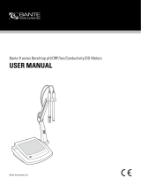
Millivolt measurements are used to mea-
sure ORP (oxidation-reduction potential)
or redox potential,to check perfor-
mance of pH or Ion Selective Electrodes,
and for redox titrations.
The meter will measure millivolts (mV) by
selecting mV mode using the mode key.
Relative mV can be measured by enter-
ing a mV offset or using a mV value as
the relative mV reference point.
Relative mV Standardization Menu
In mV mode,press std and the standard-
ize mV menu appears:
1. Auto-zero relative mV - Sets the rel-
ative mV offset equal to the nega-
tive of the current mV reading. The
current mV becomes 0.0 relative
mV.
2. Enter manual mV offset - Allows you
to enter in any mV offset.
3. Clear relative mV mode - This
clears any offset that has been
entered,returning the meter to
absolute mV mode.
4. Resolution - Allows mV readings to
be set to 1 or 0.1 millivolt.
Clearing Relative mV Mode
Press std,then press 3 – Clear relative mV
mode to clear offset and return the
meter to absolute mV mode.
Standardize mV
Channel A
1 - Auto-zero
relative mV
2 - Enter manual
mV offset
3 - Clear relative
mV mode
4 - Resolution
Electrode Potential,mV
Titrant Volume,mL
Redox Titration

The PHH-925 and PHH-950 can be used
with Ion Selective Electrodes (ISE’s) to
directly read ion concentrations.ISE’s are
connected to the channel B (BNC) input.
If a separate reference electrode is
required,connect it to the reference
input jack.
Ion Standardization Menu
Select channel B using the channel
key.Press mode and then press 3–ISE
for ion concentration mode.Press std
and the standardize menu appears.
1. Enter a standard - Allows you to
add a new standard or update
(re-enter) an existing standard.
Follow the prompts.With the first
standard you select the ion
name and units.
2. Clear standards - Clears standards
for the standardization set in current
use.
3. New ion cal - Allows for another set
of calibration standards to be
entered/stored for a different ISE.
The meter stores up to five ion cali-
brations.
4. Recall ion cal - Allows the recall of
an ion calibration set.
5. Enter slope - Allows entry of a known
slope to be used with a single-point
standardization.The normal default
slope is 59.16 mV/decade for mono-
valent ions and 29.58 mV/decade
for divalent ions at 25°C.
6. Temperature source - Allows the
meter to use the ATC (if present) or
a manually entered temperature
override*.
7. Set Isopoint - Allows you to enter an
isopotential point (See Appendix F).
8. Enter blank - Allows you to enter a
blank.
9. Resolution - Allows the readings to
be set to 1,2 or 3 digits.
Standardizing and Measuring Ion
13
Standardize ISE
Channel B
1 - Enter a standard
2 - Clear standards
3 - New ion cal
4 - Recall ion cal
5 - Enter slope
6 - Temperature source
7 - Set isopoint
8 - Enter blank
9 - Resolution
*Temperature Source
Set to Auto to use the
ATC probe (if present).
Set to manual when
samples being mea-
sured on one channel
are at a different tem-
perature from samples
with the ATC probe.Use
manual when tempera-
ture correction is not
desired or the isopoten-
tial is not known (ISE’s).

1. Add the appropriate Ionic Strength
Adjuster (ISA) solution to the stan-
dard.
2. Immerse the electrode(s) in the solu-
tion and stir continuously.
3. Press std and select 1–Enter a stan-
dard to add a standard.
4. Follow the prompts.
5. The meter waits for a stable signal
and enters the standard.The
entered standard appears in the
display.
6. Alternatively,if the signal is not sta-
ble,you can press enter when the
reading stabilizes according to your
tolerance criteria.The meter then
enters the standard.
7. Repeat steps 1 through 6 to enter a
second,third,fourth or fifth standard.
With more than one standard,the
meter performs a diagnostic check
on the electrode.
Helpful Hints:
• Provide stirring.
• Allow the electrode time to reach a
stable reading before entering the
standard into the meter.
• To achieve better accuracy,standardize
using at least two standards, bracketing
the expected range of your samples.
• Standardize from low to high concen-
trations.
• Always use fresh standards.
Clearing Standards
mV
ion standards
log [ion]

Press std, then press 2–Clear standards
to clear the current set being used.
This will not clear other stored ion cali-
brations.
The meter will automatically recognize
when a conductivity cell is attached
to the meter.
Select channel A using the channel
key.Pressing mode allows the meter
to be set to the proper units.
Conductivity modes and units are:
Conductivity - µS/cm or mS/cm.
Resistivity - Ω•cm ,kΩ•cm or MΩ•cm
Practical Salinity - salt concentration
in parts per thousand (ppt) based
upon sea water.
NaCl Salinity - sodium chloride equiva-
lent concentration in ppt.
Total Dissolved Solids (TDS) - an empiri-
cal scale relating conductivity to total
dissolved solids in ppt.
Conductivity Standardization Menu
Press std and the standardize con-
ductivity menu appears:
1. Enter standard - Allows you to
add a new standard or re-enter
an existing standard.Up to five
points may be entered.Follow
the prompts.
2. Clear standards - Clears all stan-
dards currently stored.
3. Temperature source - Allows the
meter to use the ATC (if present),
or use a manually entered temper-
ature override.
4. Enter known cell constant - Allows
you to enter the nominal or known
actual cell constant.
5. Enter temperature coefficient -
15
Select Mode
Channel A
1 - Conductivity
2 - Practical
Salinity
3 - NaCl Salinity
4 - Resistivity
5 - Total Dissolved
Solids
6 - Temperature
Standardize
Conductivity
Channel A
1 - Enter a standard
2 - Clear standards
3 - Temperature
Source
4 - Enter known
cell constant
5 - Enter temperature
coefficient
6 - Resolution
7 - Autoranging

Allows you to select the reference
temperature and the temperature
coefficient (used with conductivity).
The default setting is 1.90%/°C cor-
rection to 25°C.
6. Resolution - Allows the readings to be
set to 1,2,3 or 4 digits.
7. Autoranging (Conductivity/
Resistivity modes)- Select unit
autoranging (µS to mS,Ω to kΩ to
MΩ) or fixed units (µS, KΩ).
or
7. Solids factor (TDS mode) - enters the
solids factor used for TDS.The default
is 0.5.
Standardizing and Measuring
Conductivity, Salinity, Resistivity or TDS
1. Immerse the cell in a standard and
stir moderately.The meter displays
the current measurement.
2. Press std,then press 1 – enter stan-
dard to add or re-enter a standard.
Follow the prompts.
3. The meter waits for a stable signal,
and enters the standard.The entered
standard appears in the
display.
4. Alternatively,if the signal is not stable,
you can press enter when the read-
ing stabilizes according to your toler-
ance criteria to enter the standard.
5. Repeat steps 1 through 3 to enter a
second,third,fourth or fifth standard.
Standards must be at least two-fold
apart in value.On each standard,
the meter performs a diagnostic
check on the cell.The cell is consid-
ered bad if the cell constant is out-
side 50% and 200% of the nominal
/