Epson 201 User manual

Category
Cash registers
Type
User manual

This manual is also suitable for

Customer Display
DM-D500
Installation Manual
401156101
CAUTIONS
This document shall apply only to the product(s) identified herein.
No part of this document may be reproduced, stored in a retrieval system, or
transmitted in any form or by any means, electronic, mechanical, photocopying,
recording, or otherwise, without the prior written permission of Seiko Epson
Corporation.
The contents of this document are subject to change without notice. Please
contact us for the latest information.
While every precaution has been taken in the preparation of this document,
Seiko Epson Corporation assumes no responsibility for errors or omissions.
Neither is any liability assumed for damages resulting from the use of the
information contained herein.
Neither Seiko Epson Corporation nor its affiliates shall be liable to the purchaser
of this product or third parties for damages, losses, costs, or expenses incurred
by the purchaser or third parties as a result of: accident, misuse, or abuse of this
product or unauthorized modifications, repairs, or alterations to this product, or
(excluding the U.S.) failure to strictly comply with Seiko Epson Corporation's
operating and maintenance instructions.
Seiko Epson Corporation shall not be liable against any damages or problems
arising from the use of any options or any consumable products other than
those designated as Original EPSON Products or EPSON Approved Products by
Seiko Epson Corporation.
TRADEMARKS
EPSON
®
is a registered trademark of Seiko Epson Corporation.
Microsoft
®
, MS
®
, MS-DOS
®
, Windows
®,
Windows NT
®
are registered trademarks
of Microsoft Corporation.
General Notice: Other product and company names used herein are for
identification purposes only and may be trademarks of their respective companies.
Copyright © 1999, 2000 by SEIKO EPSON CORPORATION
1
Engli
s
h
Safety Precautions
This document presents important information intended to ensure safe and effective use
of this product. Please read this document carefully, and store it in an accessible location
near your installation.
Precaution Headings
This document uses the two headings shown below to call attention to potential hazards.
Failure to observe the information provided under or alongside these headings may lead
to injury or property damage. Be sure that you understand the meaning of each heading
before you proceed.
WARNING:
Indicates a potentially lethal hazard. Failure to observe a WARNING
may result in severe injury or death.
CAUTION:
Failure to observe a CAUTION may result in personal injury, or in damage
to equipment or other property.
Safety Precautions
WARNING:
Shut down your equipment immediately if it produces smoke, a
strange odor, or unusual noise. Continued use may lead to fire or
electric shock. Immediately turn the power off and contact your
dealer or a SEIKO EPSON service center for advice.
Never attempt to repair this product yourself. Improper repair work
can be dangerous. Tampering with this product may result in injury,
fire, or electric shock.
Be sure to use the specified power source. Connection to an
improper power source may cause fire or shock.
Do not allow foreign matter to fall into the equipment. Penetration
of foreign objects may lead to fire or shock.
If water or other liquid spills into this equipment, immediately turn the
power off and contact your dealer or a SEIKO EPSON service center
for advice. Continued usage may lead to fire or shock.
2
CAUTION:
Do not plug the cable differently from the instruction in this manual.
Wrong connection may cause equipment damage and fire.
Be sure to set this equipment on a firm, stable, horizontal surface.
Product may be damaged or cause injury if it falls.
Do not use in locations subject to high humidity or dust levels.
Excessive humidity and dust may cause equipment damage, fire, or
shock.
Do not place heavy objects on top of this product. Equipment may
be damaged and cause injury if it falls.
Do not attach plural extension supports. Product may be damaged
or cause injury if it falls.
A stopper limits the horizontal rotation of the display. Do not try to
force it to turn beyond the limits of the stopper. Doing so may
damage the equipment.
EMC and Safety Standards Applied
Product Name: DM-D500
Type Name: M151A
The following standards are applied only to the display that is so labeled. (EMC is tested
using the EPSON PS-170 power supply.)
Europe: CE Marking
Safety: EN60950
North America: EMI: FCC/ICES-003 Class A
Safety: UL 1950/CSA C22.2 No.950
Japan: EMC: VCCI Class A JEIDA-52
Oceania: EMC: AS/NZS 3548 (CISPR22) Class B
CE Marking
The display conforms to the following Directies and Norms
Directive 89/336/EEC EN55022 Class B
EN55024
IEC 61000-4-2
IEC 61000-4-3
IEC 61000-4-4
IEC 61000-4-5
IEC 61000-4-6
IEC 61000-4-11
3
Engli
s
h
WARNING
You are cautioned that changes or modifications not expressly approved by SEIKO
EPSON Corporation could void your authority to operate the equipment.
FCC COMPLIANCE STATEMENT FOR AMERICAN USERS
This equipment has been tested and found to comply with the limits for a Class A digital
device, pursuant to Part 15 of the FCC Rules. These limits are designed to provide
reasonable protection against harmful interference when the equipment is operated in a
commercial environment.
This equipment generates, uses, and can radiate radio frequency energy and, if not
installed and used in accordance with the instruction manual, may cause harmful
interference to radio communications. Operation of this equipment in a residential area is
likely to cause harmful interference in which case the user will be required to correct the
interference at his own expense.
FOR CANADIAN USERS
This Class A digital apparatus complies with Canadian ICES-003.
Cet appareil numérique de la classe A est conforme
à
la norme NMB-003 du Canada.
About This Manual
Cautions and Notes
CAUTION:
Cautions must be observed to avoid minor injury to yourself or damage
to your equipment.
Note:
Notes have important information and useful tips on the operation of your display.
4
Contents
About This Manual . . . . . . . . . . . . . . . . . . . . . . . . . . . . . . . . . . . . . . . . . . . . . . . . . . . . . . . . 3
Contents . . . . . . . . . . . . . . . . . . . . . . . . . . . . . . . . . . . . . . . . . . . . . . . . . . . . . . . . . . . . . . . . . 4
Unpacking . . . . . . . . . . . . . . . . . . . . . . . . . . . . . . . . . . . . . . . . . . . . . . . . . . . . . . . . . . . . . . . 5
Cautions on Handling. . . . . . . . . . . . . . . . . . . . . . . . . . . . . . . . . . . . . . . . . . . . . . . . . . . . . . 5
Usage. . . . . . . . . . . . . . . . . . . . . . . . . . . . . . . . . . . . . . . . . . . . . . . . . . . . . . . . . . . . . . . . . . . . 6
Precautions when connecting to a TM printer . . . . . . . . . . . . . . . . . . . . . . . . . . . . . . . . . 7
Assembling. . . . . . . . . . . . . . . . . . . . . . . . . . . . . . . . . . . . . . . . . . . . . . . . . . . . . . . . . . . . . . . 8
Attaching to the IR Series. . . . . . . . . . . . . . . . . . . . . . . . . . . . . . . . . . . . . . . . . . . . . . . 8
Attaching to the TM-H5000II/TM-J8000 . . . . . . . . . . . . . . . . . . . . . . . . . . . . . . . . . 10
Attaching to the TM-U375/TM-U950. . . . . . . . . . . . . . . . . . . . . . . . . . . . . . . . . . . . 13
Attaching to the TM-H6000/TM-U675 . . . . . . . . . . . . . . . . . . . . . . . . . . . . . . . . . . 16
Attaching to Other TM Printers . . . . . . . . . . . . . . . . . . . . . . . . . . . . . . . . . . . . . . . . 21
Attaching to the DM-D stand . . . . . . . . . . . . . . . . . . . . . . . . . . . . . . . . . . . . . . . . . . 24
Part Names and Functions. . . . . . . . . . . . . . . . . . . . . . . . . . . . . . . . . . . . . . . . . . . . . . . . . 31
Exterior . . . . . . . . . . . . . . . . . . . . . . . . . . . . . . . . . . . . . . . . . . . . . . . . . . . . . . . . . . . . . 31
DIP Switch . . . . . . . . . . . . . . . . . . . . . . . . . . . . . . . . . . . . . . . . . . . . . . . . . . . . . . . . . . . . . . 32
DIP Switch Functions . . . . . . . . . . . . . . . . . . . . . . . . . . . . . . . . . . . . . . . . . . . . . . . . . 32
Turning and Tilting the DM-D500 . . . . . . . . . . . . . . . . . . . . . . . . . . . . . . . . . . . . . . . . . . 35
Self Test. . . . . . . . . . . . . . . . . . . . . . . . . . . . . . . . . . . . . . . . . . . . . . . . . . . . . . . . . . . . . . . . . 36
Check Items of Self test. . . . . . . . . . . . . . . . . . . . . . . . . . . . . . . . . . . . . . . . . . . . . . . . 36
Performing Self test. . . . . . . . . . . . . . . . . . . . . . . . . . . . . . . . . . . . . . . . . . . . . . . . . . . 36
Specification . . . . . . . . . . . . . . . . . . . . . . . . . . . . . . . . . . . . . . . . . . . . . . . . . . . . . . . . . . . . . 37
General Specifications. . . . . . . . . . . . . . . . . . . . . . . . . . . . . . . . . . . . . . . . . . . . . . . . . 37
Electrical Specifications . . . . . . . . . . . . . . . . . . . . . . . . . . . . . . . . . . . . . . . . . . . . . . . 39
Environmental Specifications . . . . . . . . . . . . . . . . . . . . . . . . . . . . . . . . . . . . . . . . . . 39
Character Specifications . . . . . . . . . . . . . . . . . . . . . . . . . . . . . . . . . . . . . . . . . . . . . . . 40
Reliability Specification . . . . . . . . . . . . . . . . . . . . . . . . . . . . . . . . . . . . . . . . . . . . . . . 40
5
Engli
s
h
This manual explains how to set up the DM-D500.
Unpacking
The following items are in the box.
Make sure that you have all the items shown above, and that none has
been damaged. If you find anything missing or damaged items, please
contact your DM-D500 dealer.
Cautions on Handling
When you use the DM-D500, be sure to note the following points:
Avoid locations that are subject to high temperature and humidity.
Avoid dirty and dusty locations.
Avoid locations that are unstable or are subject to high levels of
vibration.
When connecting or disconnecting cables, make sure that the
power switch of the DM-D500 and printers connected to the
DM-500 are turned off.
Do not drop the DM-D500, because you may damage the built-in
vacuum fluorescent display.
i
ns
t
a
ll
a
ti
on manua
l
warranty card
(201 model only)
display (DM-D500)
6
Usage
The DM-D500 can be used with the following equiment.
IR Series. You can attach the DM-D500 to the IR Series using the
DM-D pole unit for IR (DP-504). (See page 8.)
TM-H5000II/TM-J8000 printers. You can attach the DM-D500 to
TM-H5000II/TM-J8000 printers using the DM-D pole unit for TM
printers (Type B) (DP-503). (See page 10.)
TM-U375/TM-U950. You can attach the DM-D500 to the TM-U375/
TM-U950 printers using the DM-D pole unit for TM printers
(Type A) (DP-502). (See page 13.)
TM-H6000/TM-U675. You can attach the DM-D500 to TM-H6000/
TM-U675 printers using the DM-D pole unit for TM printers
(Type A) (DP-502). (See page 16.)
Other TM printers. You can attach the DM-D500 using the DM-D
pole unit for TM printers (Type A) (DP-502) and Velcro tapes or
screws. (See page 21.)
DM-D stand. You can attach the DM-D500 to the DM-D stand
directly using the DM-D stand unit for DM-D500 (DP-501). When
using the DM-D stand, an optional power supply unit (PS-170) is
required. Also, if you want to extend the length of the DM-D500, an
optional extension support unit (DP-105) is required. (See page 24.)
7
Engli
s
h
Precautions when connecting to a TM printer
When the DM-D500 is connected to a TM printer, be sure to check the serial
number on the label affixed to the rear or bottom of the TM printer. If the serial
number is one of the numbers indicated below it can be used immediately. If
the serial number is not listed below, however, the DM-D500 cannot be
connected to the TM printer as it is. In this case, please purchase and install the
latest model of the UB-S01 board (Part code: C8233610200) before using the
DM-D500 with that printer.
If your TM or other printer is not listed below, it may be connected to the DM-
D500 without any special modifications (continued on back).
*1: If your printer is a TM-H5000, always purchase the latest model of the UB-S01 before using it with
the DM-D500.
If an old model of the UB-S01 (Part code: C8233610000)is connected to the
TM printer, please purchase and install the latest model of the UB-S01 board
(Part code: C8233610200).
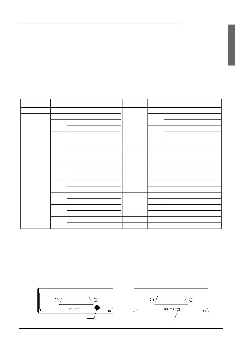
The TM printer and UB-S01 used with the DM-D500 will have one of the
following markings on the RS-232C connector mounting plate. This marking
indicates whether of not the printer can be connected to the DM-D500.
Printer Model Serial No. Printer Model Serial No.
TM-H5000 - None *1 TM-U590 101 ART0 010001 and higher
TM-H5000II 001 AR30 010001 and higher 111 ARU0 003001 and higher
011 AR40 040001 and higher ARU0 510001 and higher
AR40 530001 and higher 131 ARY0 003001 and higher
021 AR50 040001 and higher ARY0 510001 and higher
AR50 510001 and higher 141 BUV0 000001 and higher
031 AR60 040001 and higher BUV0 510001 and higher
AR60 510001 and higher TM-H6000 001 BMQ0 020001 and higher
041 AR70 040001 and higher 011 BMR0 020001 and higher
AR70 510001 and higher 021 BMS0 020001 and higher
091 BFX0 000001 and higher 031 BMT0 020001 and higher
BFX0 510001and higher 041 BV40 020001 and higher
161 BKS0 000001 and higher 061 BX50 020001 and higher
BKS0 510001 and higher 071 B7R0 020001 and higher
181 BNV0 000001and higher TM-U675 001 BMK0 020001 and higher
BNV0 510001and higher 011 BML0 020001 and higher
201 B430 000001 and higher 021 BMM0 020001and higher
B430 510001 and higher 061 BX30 020001 and higher
211 B5X0 000001 and higher TM-T285 001 2XT0 010001 and higher
B5X0 510001 and higher TM-J8000 011 AQS0 010001 and higher
Scribed square
Blue seal
8
Assembling
Attaching to the IR Series
The DM-D500 can be attached directly to the IR Series using the DM-D
pole unit for IR (DP-504).
Required items
The following items are used to attach the DM-D500 to the IR Series.
These items are packed with the DM-D pole unit for IR (DP-504).
Assembling steps
1. Pass the cable for the DM-D500 through support A, and attach
support A to the DM-D500.
When using support B for extension, insert the tab on support B
into the hole on support A until you feel it click.
base
fixing screws
support B
(for extension)
support A
When using support B for
extension
9
Engli
s
h
2. Attach the base to the setting position on the IR Series, and secure it
with the screws.
Note:
When attaching the base, note that the corners of the base are set as shown
below.
3. Pass the cable for the DM-D500 through the base.
4. Insert the tab on the base into the hole on the support until you feel
it click.
.
10
5. Connect the cable for the DM-D500 to the DM connector on the IR
Series.
Attaching to the TM-H5000II/TM-J8000
The DM-D500 can be attached directly to the TM-H5000II/TM-J8000
printers using the DM-D pole unit for TM printers (Type B) (DP-503).
Required items
The following items are used to attach the DM-D500 to the
TM-H5000II/TM-J8000 printers. These items are packed with the
DM-D pole unit for TM printers (Type B) (DP-503).
base
fixing screws
support C
support B
(for extension)
11
Engli
s
h
Assembling steps
1. Pass the cable for the DM-D500 through support C, and attach
support C to the DM-D500.
When using support B for extension, insert the tab on support B
into the hole on support C until you feel it click.
2. Attach the base to the setting position on the TM printer and secure
it with the screws.
When using support B for
extension
12
3. Pass the cable for the DM-D500 through the base.
4. Insert the tab on the base into the hole on the support until you feel
it click.
5. Connect the cable for the DM-D500 to the DM connector on the TM
printer.
13
Engli
s
h
Attaching to the TM-U375/TM-U950
The DM-D500 can be attached directly to the TM-U375/TM-U950
printers using the DM-D pole unit for TM printers (Type A)
(DP-502).
Required items
The following items are used to attach the DM-D500 to the TM-U375/
TM-U950 printers. These items are packed with the DM-D pole unit
for TM printers (Type A) (DP-502).
rubber feet
(square)
ru
bb
er
f
ee
t
(large)
rubber feet
(square)
fixing screws
for rubber feet
(large)
f
ixing screws
for metallic
portion
fi
x
i
ng screws
for plastic position
<For TM-U375>
<For TM-U950>
fixing plate A
<For TM-U375 and TM-U950>
support C
support B
for extension
14
Assembling steps
1. Pass the cable for the DM-D500 through support C, and attach
support C to the DM-D500.
When using support B for extension, insert the tab on support B
into the hole on support C until you feel it click.
2. Attach the rubber feet to the printer.
When using support B
for extension
[TM-U375]
[TM-U950]
15
Engli
s
h
3. Pass the cable for the DM-D500 through the hole on fixing plate A,
and fix the cable at the bottom as shown below.
4. Connect the cable for the DM-D500 to the DM connector on the TM
printer.
5. Adjust the length of the cable and secure fixing plate A to the
printer with screws.
[TM-U375] [TM-U950]
16
6. Store any excess cable in the support, and attach the DM-D500 to
fixing plate A.
Attaching to the TM-H6000/TM-U675
The DM-D500 can be attached directly to the TM-H6000/TM-U675
printers using the DM-D pole unit for TM printers (Type A)
(DP-502). You can attach fixing plate A on either side of the
TM-H6000/TM-U675. After attaching it, you can slide the display
freely.
Required items
The following items are used to attach the DM-D500 to the TM-H6000/
TM-U675 printers. These items are packed with the DM-D pole unit
for TM printers (Type A) (DP-502).
stopper
fixing screw
for stopper
angle fixing
screw
fixing plate B
fixing screws for
rubber feet (small)
rubber feet (small)
fixing screws for
fixing plate B
support C
fixing plate A
support B
for extension
17
Engli
s
h
Assembling steps
1. Pass the cable for the DM-D500 through support C, and attach
support C to the DM-D500.
When using support B for extension, insert the tab on support B
into the hole on support C until you feel it click.
2. Attach the rubber feet to the printer.
3. Attach fixing plate B to the printer.
When using support B
for extension
18
4. Pass the cable for the DM-D500 through the hole on fixing plate A,
and fix the cable at the bottom as shown below.
5. Connect the cable for the DM-D500 to the DM connector on the TM
printer.
6. Attach fixing plate A to the TM printer using the stopper. When
you attach the stopper, insert the projections on the stopper into the
holes of fixing plate B. Fixing plate A can be attached on either side
of the printer. (The illustration below shows fixing plate A attached
to the right side of the printer.)
  • Page 1 1
  • Page 2 2
  • Page 3 3
  • Page 4 4
  • Page 5 5
  • Page 6 6
  • Page 7 7
  • Page 8 8
  • Page 9 9
  • Page 10 10
  • Page 11 11
  • Page 12 12
  • Page 13 13
  • Page 14 14
  • Page 15 15
  • Page 16 16
  • Page 17 17
  • Page 18 18
  • Page 19 19
  • Page 20 20
  • Page 21 21
  • Page 22 22
  • Page 23 23
  • Page 24 24
  • Page 25 25
  • Page 26 26
  • Page 27 27
  • Page 28 28
  • Page 29 29
  • Page 30 30
  • Page 31 31
  • Page 32 32
  • Page 33 33
  • Page 34 34
  • Page 35 35
  • Page 36 36
  • Page 37 37
  • Page 38 38
  • Page 39 39
  • Page 40 40
  • Page 41 41
  • Page 42 42

Epson 201 User manual

Category
Cash registers
Type
User manual
This manual is also suitable for

Ask a question and I''ll find the answer in the document

Finding information in a document is now easier with AI