Page is loading ...

1 Rev. 1.2 28/09/2011
LRX 2239 ELECTRONIC PANEL
12/24*VDC low voltage electronic control unit, for the
automation of swinging and rolling gates with incorporated
receiver and battery charger.
- Mod. LG 2239 : without radio receiver
- Mod. LRS 2239 : 433.92 Mhz
- Mod. LRS 2239 SET : 433.92 Mhz “narrow band”
- Mod. LRH 2239 : 868.3 Mhz “narrow band”
TECHNICAL DATA:
- Transformer power supply: 230 Vac 50/60Hz 120W max.
- Control unit power supply: 12 Vac /20*Vac 50/60Hz 120W
max.
- Flashing light output : 12/24* Vdc 4 W max.
- Emergency battery input : 12 Vdc 7A/h max.
- Motor outputs : 12/24*Vdc 2 x 50 W max.
- Electric lock output : 12/24* Vdc 12W max.
- Power supply to photocells : 12/24* Vdc 3 W max.
- Indicator light output : 12 Vdc 3 W max.
- Working temperature : -10 - 55 °C
- Radio receiver : refer to type
- Op. transmitters : 12-18 Bit or Rolling Code
- TX max codes in memory : 120 (CODE or CODE PED)
- Dimensions of container : 240x190x110 mm.
- Protection degree : IP 56
* If using 24Vdc motors, replace the transformer provided
with a 230/20 Vac transformer the power of which is suited
to the type of motor used (120W max; the outputs for the
flashing light, electric lock and photocell power supply will
adapt to the voltage of 24Vdc, but it is only ever possible
to connect a 12Vdc battery, even when using 24Vdc
motors).
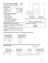
TERMINAL BOARD CONNECTIONS:
CN1 :
1 : Power supply input 12 / 20* Vac 120W max.
2 : Power supply input 12 / 20* Vac 120W max..
3 : Input + Emergency battery 12Vdc 1.2 / 7 Ah max.
4 : Input – Emergency battery 12Vdc 1,2 / 7 Ah max.
5 : Input + Solar panel
6 : Output + Flashing light 12/24*Vdc 4W max.
7 : Output - Flashing light 12/24*Vdc 4W max.
8 : Output + Motor 1.
9 : Output - Motor 1.
10 : Output + Motor 2.
11 : Output - Motor 2.
CN2 :
1 : Electric lock Output (+ 12/24*Vdc 12W).
2 : Electric lock Output (+ 12/24*Vdc 12W).
3 : Control and power supply to photocells (+ 12/24*Vdc 3W ).
4 : Control and power supply to photocells (+ 12/24*Vdc 3W ).
5 : Indicator light output (+ 12Vdc 3W ).
6 : Indicator light output (- 12Vdc 3W ).
7 : Open-Close/Open push button input (NO).
8 : Pedestrian / Close push button input (NO), DS AUX (NC).
9 : Common GND input.
10: Block input (NC).
11: Safety device input (NC).
12: Opening limit switch input for motor 1 (NC).
13: Closing limit switch input for motor 1 (NC).
14: Common GND input.
15: Opening limit switch input for motor 2 (NC).
16: Closing limit switch input for motor 2 (NC).
17: Aerial earth input.
18: Aerial hot pole input.
OPERATING CHARACTERISTICS:
Automatic:
Using either the radio control (CODE led lit) or the low tension
button panel (PUL) to operate the gates, commands will have
the following effect: the first command impulse activates the
opening mechanism either for the pre-set motor operating
interval or until the activation of the opening limit switch. The
second command impulse closes the gate. If a command
impulse is received before the activation of the limit switch the
direction of movement of the mechanism will be reversed
whether engaged in opening or closing operations.
Step-by-step:
Using either the radio control (CODE led lit) or the low tension
button panel (PUL) to operate the gates, commands will have
the following effect: the first command impulse activates the
opening mechanism either for the pre-set motor operating
interval or until the activation of the opening limit switch. The
second command impulse closes the gate. If a command
impulse is received before the activation of the limit switch the
movement of the mechanism will be stopped. A further
command impulse will reactivate the mechanism in the
opposite direction.
Automatic closing:
The mechanism may be set up to automatically close the gate
without sending additional commands.
The set-up procedure is described in the instructions for setting
the delay period.
Pedestrian access:
Using the radio command (the CODE PED. led is on) or the
button panel (PED), you can activate just motor 1 for the
programmed length of time (T.MOT.PED. led).
Block input:
The control board allows for the connection of a blocking button
(NC). Commands from the button during any phase will
immediately stop the movement of the gate. A further
command will only be executed if the blocking mechanism is
deactivated, and in any case normal automatic opening will
work.
If not used the terminals must be jumped.
Safety device:
The control board allows for the connection and control of
photocells in accordance with directive EN 12453.
Commands from the device during the opening phase will be
ignored, and when the gate is closing they will reverse the
direction of movement.
The control board needs the photocells to be connected to their
respective dedicated inputs, otherwise it will not work.
AUX 1 safety device (PED input):
The control unit, when configured, can be fitted with an
Auxiliary 1 safety device together with the Pedestrian Input
(NC).
Commands from the device during the opening phase will stop
the gate temporarily; when reactivated, the control unit
continues the opening phase. Commands whilst the gate is
closing will reverse the direction of movement.
AUX 2 safety device (PED input):
The control unit, when configured, can be fitted with an
Auxiliary 2 safety device together with the Pedestrian Input
(NC).
Commands from the device during an opening or closing phase
temporarily reverse and then stop the movement.
Opening and closing limit switch:
The control unit permits the connection of an Opening and
Closing limit switch for each Motor (NC). Commands from the
GB

2 Rev. 1.2 28/09/2011
limit switches during the respective work phases stop the
respective motors immediately.
Warning: Connect the limit switches, if available;
otherwise do not jump the FA1, FC1, FA2 or FC2 inputs
on the terminal board.
Initial pick-up and motor power adjustment:
The electronic control unit is equipped with a VR1 trimmer for
initial pick-up and motor power adjustment that are fully
managed by the microprocessor. Adjustment can be within a
range of 50% to 100% of max power.
Warning: you will need to repeat the teach-in phase if you
wish to adjust the VR1 trimmer as the operation and
deceleration times may be affected.
Obstacle detection:
The electronic control unit has a VR2 trimmer for adjusting the
power required to detect obstacles. You can control this entirely
from the microprocessor.
The trimmer’s activation time can be set between a minimum of
0.1 seconds and a maximum of 3 seconds.
Warning:
- When limit switches are connected to the control unit, the
detection of an obstacle causes the motor to change direction
during the closing phase and reverse for 2 seconds during
the opening phase.
- When no limit switches are connected to the control unit, the
detection of an obstacle always causes the motor to change
direction during the closing phase (and then take 5 seconds
to close) and reverse for 2 seconds during the opening phase
(and then take 5 seconds to stop).
Deceleration:
The motor deceleration function is used to avoid the gates
moving at high speed towards the end of the opening and
closing stages.
Deceleration can be programmed for the desired points
(before the gates are totally open or closed) during Motor Timer
programming.
Warning light:
The centre allows the connection of a 12Vdc 3 W (max)
light to show the state of the automation process. Light off
automation closed, access open, slow flashing motor
open, fast flashing motor closing.
Functioning of the Flasher or courtesy light:
The control unit has an output for the use of a flasher of
12/24*Vdc 4W max. Its use is conditioned by the settings
selected in Extended Menu 2.
Electric lock control Output:
The control unit has an output for the use of electric locks of
12/24*Vdc 12W max. It is activated for 2 seconds during each
initial opening phase.
Buffer battery:
The control unit has an incorporated 13.7 Vdc battery charger
(you need to use 12V batteries, even for 24V motors). The
control unit can be fitted with a buffer battery not exceeding
7Ah in capacity, which can be used for up to 20/30 complete
phases. The flashing light, if fitted, turns on for only the first 4
seconds of the phase in the event of a power cut.
Solar panel:
The control unit can be fitted with a solar panel for charging the
emergency battery.
Operation with TIMER:
The control unit may be connected to a timer instead of using
the open-close command button (PUL).
Example: at 8:00 a.m. the timer closes the contact and the
control unit opens the gate; at 6:00 p.m. the timer opens the
contact and the control unit closes the gate. Between 8:00 a.m.
and 6:00 p.m. at the end of the opening phase, the control unit
disables the flashing beacon, the automatic closing stage and
the radio controls.
PROGRAMMING:
SEL key: selects the type of function to be stored; selection is
indicated by a flashing LED.
By pressing the key repeatedly, you can select the desired
function. The selection remains active for 10 seconds
(indicated by the flashing LED); after 10 seconds, the control
unit returns to its original status.
SET key: programmes the information according to the type of
function selected previously using the SEL key.
IMPORTANT: The function of the SET key can be replaced with
the radio control, if programmed previously (CODE LED on).
MAIN MENU
The control unit is supplied by the manufacturer with the option
of selecting a number of principal functions.
---------------------- MAIN MENU -----------------
Led reference Led off Led on
1) TIPO MOTOR Linear Variable
2) AUTO PGM Automatic PGM = OFF Automatic PGM = ON
3) CODE No code Code activated
4) CODE PED. No code Code activated
5) T. MOT. 30 sec. activity Programmed delay
6) T.MOT.PED. 10 sec. pedestrian activity Programmed delay
7) T. PAUSA. No automatic close Automatic close
8) RIT. ANTE No gate delay Programmed delay
1) TYPE OF MOTOR:
The control unit has, by default, the operating logic for
connecting linear actuators (TIPO MOTORE Led off). To enable
the operating logic for connecting variable consumption motor
reducers (TIPO MOTORE Led on), proceed as follows: press
the SEL button until the TIPO MOTORE Led flashes, then
press the SET button. The TIPO MOTORE Led turns on and
remains steady. Repeat the procedure to restore the previous
configuration.
2) AUTO PGM:
The control unit allows you to execute (Simplified) Automatic
Programming.
Firstly, move the gates to their half-way position, press the SEL
button until the AUTO PGM flashes, then press and hold the
SET button; Motor 2 executes the closing phase up to the limit
switch or stop, and then Motor 1 does the same. If the motors
move in the wrong direction, release the SET button, unplug
the control unit and connect the wires properly to the motors. If
instead the motors act as required, the control unit should
execute a complete opening and closing phase and therefore
the entire auto programming procedure (you need to press and
hold the SET button until the end of the Auto Programming
procedure).
At the same time, the deceleration cycle is automatically
configured at 15% of the complete cycle.
During automatic programming, you can use the radio control
key on the control unit instead of the SET key, if stored
previously.
3) CODE: (Radio control code)
The control unit can store up to 150 radio controls with different
fixed or rolling codes.
Programming.
To programme the transmission code, proceed as follows:
press the SEL key until the CODE LED flashes and send the
desired code with the relevant radio control; programming is
completed when the CODE LED turns on and remains steady.
If you have stored 150 codes and you repeat the programming

3 Rev. 1.2 28/09/2011
operation, all the programming LEDs will start flashing to
indicate that no more codes can be stored.
Deleting the codes.
All the stored codes are deleted as follows: press the SEL
button until the CODE led flashes, then press the SET button
and the CODE led turns off and the codes are deleted.
4) CODE PED: (Pedestrian radio control code)
The programming and deleting procedure is the same as the
one illustrated above except that the led selected should be
CODE PED.
5) MOTOR TIME and DECELERATION:
(Programming a motor
operation time of max 4 minutes)
The control unit is supplied by the manufacturer with a default
motor operation time of 30 seconds, without deceleration.
To modify the operation time of motors 1 and 2, proceed as
follows when the gate is closed: use the SEL key to navigate to
T.MOT when the respective LED is flashing, then press the
SET key briefly and motor 1 will begin its opening cycle; when
the initial point of deceleration is reached press the SET key
again: the T.MOT LED will start flashing more slowly and motor
1 will decelerate; when the desired position is reached, press
the SET key to complete the opening cycle. The T.MOT LED
now starts flashing normally again and motor 2 will begin its
opening cycle; program the work time for Motor 2, following the
same instructions as for Motor 1. After programming the
opening times for the motors, motor 2 will start its closing cycle:
repeat the same instructions as above for programming the
closing cycle of motor 2 and then for motor 1.
To deactivate the deceleration function during programming,
once the opening and closing cycle is completed, press the
SET key twice in succession instead of just once.
When programming, you can use the radio control key on the
control unit instead of the SET key, if stored previously.
6) T. MOT. PED:
(Programming pedestrian operation time of max 4
minutes)
The control unit is supplied by the manufacturer with predefined
operation time of Motor 1 (Pedestrian) of 10 seconds without
deceleration.
To modify the pedestrian operation time, follow this procedure
with the shutter closed: with the SEL key go to T.MOT.PED.
LED when flashing, then press the SET key rapidly, Motor 1
starts the opening cycle; when the initial point of deceleration is
reached press the SET key again, the motor decelerates until
the desired position is reached, press the SET key to complete
the opening cycle. The T.MOT.PED LED starts flashing rapidly,
now repeat the programming operation for closing. To
deactivate the deceleration function, during programming, once
the opening and closing cycle is completed, press the SET key
twice in a sequence.
During programming the radio control key of the control unit
can be used instead of the SET key, if stored previously.
7) T. PAUSA:
(Programming the aut. Closing time – 4 min max.)
The control unit is supplied by the manufacturer without an
automatic closing procedure. To enable the automatic closing
function proceed as follows: use the SEL key to navigate to T.
PAUSA when the respective LED is flashing, then press the
SET key again briefly; the automatic closing time is stored and
the T. PAUSA LED remains lit constantly.
To restore the initial configuration (without automatic closing)
navigate to T.PAUSA when the respective LED is flashing then
press the SET key twice within 2 seconds; the LED switches off
and the operation is complete.
When programming, you can use the radio control key on the
control unit instead of the SET key, if stored previously.
8) T. RIT. ANTE: (Programming door delay of max. 15 sec.)
The control unit is supplied by the manufacturer without door
delay during opening and closing. To programme the door
delay time, follow this procedure with the shutter closed: with
the SEL key to the RIT.ANTE LED when flashing, press the
SET key, wait for the desired interval of time, then press the
SET key again; the fixed door delay time of 2 seconds during
opening is stored, the door delay time during closing is stored
for the programmed time and the RIT.ANTE LED is on.
To restore the initial configuration (without door delay) go to the
RIT.ANTE LED when flashing then press the SET key twice
within 2 seconds; the LED goes off and the operation is
completed.
EXTENDED MENU 1
The control unit is supplied by the manufacturer with only the
option of directly selecting the functions listed in the main
menu.
To enable the functions listed in extended menu 1, proceed as
follows: press the SET button and hold for 5 seconds; the
T.PAUSA and RIT. ANTE LEDs will flash in alternation and you
have 30 seconds to select the functions of Extended Menu 1
using the SEL and SET buttons; after another 30 seconds, the
control unit returns to the main menu.
---------------------- EXTENDED MENU 1 -----------------
Led reference Led off Led on
A) TIPO MOTORE INB. CMD AP = OFF INB. CMD AP.
= ON
B) AUTO PGM Electronic brake = ON Electronic brake = OFF
C) CODE Automatic Step-by-step
D) CODE PED. Aries effect = OFF Aries effect = ON
E) T. MOT. Closure effect = OFF Closure effect = ON
F) T.MOT.PED. Follow Me = OFF Follow Me = ON
G) T. PAUSA Flashing beacon ON/OFF in alternation
H) RIT. ANTE Flashi
ng beacon ON/OFF in alternation
A) TYPE OF MOTOR
(
command inhibition during opening and pause time, if
entered
) :
The command inhibition function during opening and pause
time, if entered, is used when automation includes the loop
detector. During opening or pause the control unit does not
detect the commands given by the loop detector at every
passage.
The control unit is supplied by default with the command
inhibition function during opening and pause time not enabled.
To enable the function follow this procedure: check that the
Extended Menu 1 is enabled (the T.PAUSA and RIT ANTE
LEDs start flashing in alternation), use the SEL key to navigate
to TIPO MOTORE when the respective LED is flashing, and
press the SET key: the TIPO MOTORE LED switches on and
programming is complete.
Repeat the operation to restore the previous configuration.
B) AUTO PGM (Electronic brake) :
The control unit is supplied by the manufacturer with the
electronic brake function disabled. To enable the function
proceed as follows: check that the extended menu 1 is enabled
(the T. PAUSA and RIT ANTE LEDs start flashing in
alternation), use the SEL key to navigate to AUTO PGM when
the corresponding LED is flashing and press the SET key: the
AUTO PGM LED switches on and programming is complete.
The control unit reduces the forward motion of the gate due to
inertia in the presence of a stop or inversion command. Repeat
the operation to restore the previous configuration.
C) CODE (Automatic/Step-by-step operation):
The control unit has, by default, the operating logic for
“automatic” operation. To select the operating logic for “step-
by-step” operation, proceed as follows: check that the Extended
Menu 1 is enabled (the T.PAUSE and RIT ANTE LEDs start
flashing in alternation), press the SEL key until the CODE Led
flashes, then press the SET key; the CODE Led turns on and
remains steady and programming is complete. Repeat the
operation to restore the previous configuration.
D) CODE PED. (Aries (ramming) effect) :

4 Rev. 1.2 28/09/2011
The control unit is supplied by the manufacturer with the aries
(ramming) effect function disabled. To enable the Aries
(ramming) effect at maximum power, proceed as follows: check
the extended menu 1 is enabled (the T.PAUSA and RIT ANTE
LEDs flash in alternation), press the SEL key until the CODE
PED Led flashes, then press the SET key, at the same time the
CODE PED LED turns on and remains steady and
programming is complete. To enable the Aries (ramming) effect
at the power configured using the VR1 Trimmer, repeat the
above procedure, pressing the SEL key twice (the CODE PED
Led flashes quickly) instead of once. Repeat the operation to
restore the previous configuration.
In this way the lock can be unlocked and the opening phase
can be executed correctly. Before starting the opening process,
the control unit sends a closing command for 2 seconds, at a
power associated with the selection.
E) T. MOT. (Closure strike):
The control unit is supplied by the manufacturer with the
closure strike function not enabled. To enable the function,
proceed as follows: check the extended menu is enabled (the
T. PAUSA and RIT. ANTE LEDs flash in alternation), press the
SEL key until the T. MOT. LED flashes, then press the SET
key: the T. MOT. LED turns on and programming is complete. If
you wish to enable the Closure strike function at the configured
power with the VR1 trimmer, repeat the above procedure,
pressing the SEL key twice (the T.MOT. Led flashes quickly)
instead of once. Repeat the operation to restore the previous
configuration.
If Deceleration during closing is programmed, the control unit
will add 1-sec time at the power associated with the selection
(after completing the decelerated closing phase) in order to
overcome the lock, if present.
F) T. MOT. PED. ( Follow Me ) :
The control unit is supplied by the manufacturer with the Follow
Me function not enabled. To enable the function, proceed as
follows: check the extended menu 1 is enabled (the T.PAUSA
and RIT ANTE LEDs flash in alternation), press the SEL button
until the T.MOT.PED Led flashes, then press the SET key; at
the same time the T.MOT.PED LED turns on and remains
steady and programming is complete. In this way the control
unit executes the closing phase immediately, ignoring the
configured operating logics, if it detects transit with activation of
the photocell connected to the DS input during the opening,
Pause and Closing phases.
Repeat the operation to restore the previous configuration.
EXTENDED MENU 2
The control unit is supplied by the manufacturer with only the
option of directly selecting the functions listed in the main
menu.
To enable the functions listed in Extended Menu 2, proceed as
follows: open Extended Menu 1 (as instructed in the respective
section), then press and hold the SET key for 5 seconds; the
T.PAUSA and RIT ANTE LEDs flash at the same time; you
have 30 seconds to select the functions of Extended Menu 2
using the SEL and SET buttons; after another 30 seconds, the
control unit returns to the main menu.
---------------------- EXTENDED MENU 2 -----------------
Led reference Led off Led on
A) TIPO MOTORE Remote PGM = OFF Remote PGM = ON
B) AUTO PGM Photocell test= OFF Photocell test = ON
C) CODE Pre-flash and Cour. light=OFF Pre-flash or Cour. light
=ON
D) CODE PED. Flash in Pause = OFF Flash in Pause = ON
E) T. MOT. PUL=PUL/PED=PED PUL=PUL/PED=DS AUX1/2
F) T.MOT.PED. PUL=PUL / PED=PED PUL=AP / PED=CH
G) T. PAUSA Flash ON/OFF simultaneously
H) RIT. ANTE Flash ON/OFF simultaneously
A) TYPE OF MOTOR
(Remote programming of radio control):
The control unit enables remote programming of the
transmission code, without using the SEL key.
To program the transmission code in remote mode, proceed as
follows: send the previously stored radio control code
continuously for more than 10 seconds and the control unit will
enter the programming mode as described above for the CODE
Led in the main menu.
The control unit is supplied by the manufacturer with remote
programming of the transmission code not enabled; to enable
the function proceed as follows: check the extended menu 2 is
enabled (the T. PAUSA and RIT. ANTE LEDs flash
simultaneously), press the SEL button until the TIPO MOTOR
LED flashes, then press the SET key, at the same time the LED
TIPO MOTOR turns on and remains steady and programming
is complete. Repeat the operation to restore the previous
configuration.
B) AUTO PGM (Photocell Test):
The control unit is supplied by the manufacturer with
programming of the Photocell Test disabled; to enable the
function (in accordance with standard EN 12453), proceed as
follows: check the extended menu 2 is enabled (the T. PAUSA
and RIT. ANTE LEDs flash simultaneously), press the SEL
button until the AUTO PGM Led flashes, then press the SET
key, at the same time the LED AUTO PGM turns on and
remains steady and programming is complete. In this way, the
Photocell connected to the DS input is tested before the
automation starts any of the phases.
Repeat the operation to restore the previous configuration. If
not used, the DS input must be jumped and the Photocell Test
disabled.
C) CODE (Pre-flash/ Courtesy Light):
The control unit is supplied by the manufacturer with the Pre-
flash and Courtesy Light functions not enabled. To enable the
Pre-flash function, proceed as follows: check the Extended
Menu 2 is enabled (the T. PAUSA and RIT. ANTE LEDs flash
simultaneously), press the SEL key until the CODE LED
flashes, then press the SET key, at the same time the CODE
LED turns on and remains steady and programming is
complete. To enable the Courtesy light function, repeat the
above procedure, pressing the SEL key twice (the CODE LED
flashes quickly) instead of once. Repeat the operation to
restore the previous configuration.
Pre-flashing: The 12 Vdc 4 W light output is always activated
3 seconds before the automation starts any of the phases.
Courtesy light: The 12 Vdc 4W light output is activated for 3
seconds whenever an opening command is transmitted.
D) CODE PED (Use of the Flashing Beacon) :
The control unit is supplied by the manufacturer with use of the
flashing beacon during the Pause Time disabled. To enable
use of the flashing beacon, check the Extended Menu 2 is
enabled (the T. PAUSA and RIT. ANTE LEDs flash
simultaneously), press the SEL key until the CODE PED LED
flashes, then press the SET key, at the same time the CODE
PED LED turns on and remains steady and programming is
complete. Repeat the operation to restore the previous
configuration.
E) T. MOT. (Selection of the PED / DS AUX1-AUX2 input) :
The control unit is supplied by the manufacturer with a PED
input for connecting a cyclical (NO) Pedestrian control button.
To select use of the input as DS AUX 1, proceed as follows:
check the Extended Menu 2 is enabled (
the T. PAUSA and RIT.
ANTE LEDs flash simultaneously), press the SEL key until the
T.MOT. LED flashes, then press the SET key, at the same time
the T.MOT. LED turns on and remains steady and
programming is complete
.
Repeat the operation to restore the previous configuration.
To select use of the input as DS AUX 2, repeat the above
procedure for use as DS AUX 1, pressing the SEL key twice
(the T. PAUSA and RIT. ANTE LEDs flash quickly and at the
same time) instead of once.

5 Rev. 1.2 28/09/2011
Repeat the operation to restore the previous configuration.
F) T. MOT. PED. (Selection of the PUL and PED inputs) :
The control unit is supplied by the manufacturer with a PUL
control input for connecting a cyclical (NO) main control button,
and a PED control input for connecting a cyclical (NO)
Pedestrian control button. To select a different use for the PUL
and PED inputs, proceed as follows: check the Extended Menu
2 is enabled (the T. PAUSA and RIT. ANTE LEDs flash
simultaneously), press the SEL button until the T.MOT.PED
Led flashes then press the SET key, at the same time the
T.MOT.PED LED turns on and remains steady and
programming is complete.
In this way, the PUL input enables connection of a (NO) button
just for the opening phase, and the PED input enables
connection of a (NO) button just for the closing phase. Repeat
the operation to restore the previous configuration.
EXTENDED MENU 3
The control unit is supplied by the manufacturer with only the
option of directly selecting the functions listed in the main
menu.
To enable programming of the control unit’s deceleration
power, proceed as follows: open Extended Menu 2 (as
instruction in the respective section), then press and hold the
SET button for 5 seconds at the end of which the T.PAUSA and
RIT. ANTE LEDs flash in alternation and then simultaneously;
you have 30 seconds to select the required deceleration value
using the SEL and SET buttons; after another 30 seconds, the
control unit returns to the main menu.
---------------------- EXTENDED MENU 3 -----------------
Level LEDs on
1 TIPO MOTORE
2 TIPO MOTORE - AUTO PGM
3 TIPO MOTORE - AUTO PGM - CODE
4 TIPO MOTORE - AUTO PGM - CODE - CODE PED.
5 TIPO MOTORE - AUTO PGM - CODE - CODE PED. - T. MOT.
6 TIPO MOT. - AUTO PGM - CODE - CODE PED. - T. MOT. - T.MOT.PED.
Programming deceleration
The control unit allows you to program the power for the
deceleration phase.
You can choose between 6 different levels of power: each
combination of lighted LEDs is associated with a level, as
indicated in the table above; in practice, the number of LEDs
switched on (starting with the TIPO MOTORE Led) indicates
the level of power. Use the SEL button to scroll through the
levels of power; for each level of power selected, the highest
LED in the respective set flashes (for instance, if you select
level 4, the TIPO MOTORE, AUTO PGM and CODE LEDs are
steady while the CODE PED Led flashes); press SET to
confirm.
The default setting is Level 3.
RESET:
To restore the default configuration, press the SEL and
SET keys simultaneously; all RED LEDs will light up and
then switch off.
DIAGNOSTICS:
Photocell test:
The control unit can be fitted with safety devices in accordance
with step 5.1.1.6 of the EN 12453 standard. Each work cycle
includes a test to check the working order of the connected
photocell. If the photocell is not connected and/or not working,
the control unit disables operation and all the LEDs flash at the
same time to indicate the test has failed. The photocell has to
be fixed before the control unit can be put to normal use again.
This guarantees monitoring of faults in according with Category
2 of EN 954-1.
Command input test:
The control unit is fitted with a LED for each low voltage
command input, allowing you to monitor status quickly.
Operating principle: LED on = input closed, LED off = input
open.
F
OR THE USER
–
IMPORTANT
- The device should not be used by children or by
individuals with reduced physical or psychological abilities
unless supervision is provided or instruction given on how
to operate it.
- Do not let children play with the device; keep radio
controls out of their reach.
- CAUTION: Keep this instruction manual in a safe place
and adhere to the important safety instructions contained
within it. Non-adherence to these instructions may lead to
property damage and serious accidents.
- Examine the system frequently to check for any signs of
damage. Do not use the device if it needs to be repaired.
Warning
All operations which require the casing to be opened (such as
wire connection, programming, etc.) must be carried out during
installation, by skilled staff only.
For any other procedure which requires the casing to be
opened again (programming, repairs or site modifications),
please contact the technical assistance service.

6 Rev. 1.2 28/09/2011
I
MPORTANT NOTES FOR THE INSTALLER
−
Before shutter automation, it is necessary to check
the product is in good condition and that it complies
with EN 12604 and the Machines Directive.
−
The control unit is not equipped with a 230 V a/c
electric line sectioning device. The installer is
responsible for installing a sectioning device in the
system.
It is essential to install an overvoltage category
III omnipolar disconnect switch The sectioning device
must be positioned so that it is protected against
accidental closure, in compliance with section 5.2.9 of
standard EN 12453.
−
The wiring of external electrical components must
comply with EN 60204-1 as amended in section
5.2.7 of EN 12453. Power supply leads and
connection cables must be secured through the use
of cable clamps, which are supplied with the
product.
− As for power cables, we recommend using H05RN-F
harmonised polychloroprene sheathed flexible cables with
conductor cross-section of at least 0.5mm
2
− The declared IP rating refers to before the
intstallation.Take care when drilling the outer casing to
feed through the power and connecting cables and when
assembling the cable glands, to maintain the IP degree
of protection of the casing as best as possible. Also take
care to fasten the cables firmly in place.
− The back of the casing is set up for mounting on a wall
(holes for mounting with nogs, or holes for screws). Take
all precautions to ensure the IP degree of protection is
not affected during installation.
− If applicable, the keypad for manual control must be
mounted in such a way as not to compromise the safety
of the user.
−
The motor reducer used to move the shutter must
comply with section 5.2.7. of EN 12453.
− The D.S. Power Supply output is specifically for powering
the photocells. It must not be used for any other
applications.
− The control unit tests the working order of the photocells
for each work cycle to guarantee the safety of the
Category 2 anti-crushing devices in accordance with step
5.1.1.6 of EN 12453. The control unit is disabled
whenever the safety devices are not connected and/or
not in good working order.
− For the radio receiver to operate correctly when two
more control units are used, we recommend that you install
the devices at least 3 metres away from each other.
the product:
Electronic panel:
LG 2239 - LRS 2239 - LRS 2239 SET - LRH 2239
Complies with the requirements of Directives
R&TTE 99/5/EC, EMC 2004/108/EC, LVD 2006/95/EC.

7 Rev. 1.2 28/09/2011
/