Extron DTP T USW 233 User manual

Category
Video switches
Type
User manual
1
DTP T USW 233 • Setup Guide
This guide provides instructions for an experienced installer to set up and operate the
Extron DTP T USW 233 switching video transmitter. The DTP T USW 233 transmitter switches among
an analog video and two digital (HDMI) video inputs and, paired with a compatible receiver, can
extend the selected signal up to 230 feet (70 m). If the selected input is HDMI, the extended video
signal is HDCP-compliant.
Installation
Step 1 — Mounting
Turn off or disconnect all equipment power sources and mount the transmitter as required.
Step 2 — Making Connections
Inputs
A
Input 1 (RGB) connector — Connect a VGA cable between this port and the VGA output port of the analog video source.
B
Input 2 and 3 (HDMI) connectors — Connect HDMI cables between these ports and the HDMI output ports of the digital video
sources.
NOTE: See the LockIt
®
Lacing Brackets on page 3 of this guide to securely fasten the HDMI connectors to the transmitter.
C
TP function switch
If the receiving device is in the Extron DTP series, set this switch to DTP. The TP output consists of HDMI with embedded audio,
analog audio, RS-232 and IR, and remote power. The transmitter and receiver can be powered by one 12 VDC power supply
connected to either unit.
For an HDBaseT-enabled receiver type, set this switch to HDBT position. The TP output consists of HDMI with embedded audio plus
RS-232 and IR. The transmitter and receiver each requires its own 12 VDC power supply.
ATTENTION:
Position this switch BEFORE connecting the appropriate device to the TP connector. Failure to comply can damage the
endpoint.
Positionnez le sélecteur AVANT de connecter l’appareil approprié au connecteur TP. Ne pas respecter cette procédure
pourrait endommager le point de connexion.
D
Audio input — Connect an unbalanced stereo audio source to this 3.5 mm mini stereo jack for an analog audio input.
NOTE: Analog input audio is not embedded in the HDMI signal; it is transmitted separately and is present for any selected input.
Over DTP RS-232 and IR pass-through
E
RS-232 and IR connector — To pass serial or infrared data or control signals on the Over
DTP RJ-45 output, connect the controlling device to the transmitter via the RS-232 and IR
captive screw connector. Connect the device to be controlled to the receiver.
POWER
12V
2
--A MAX
Rx GTx RxTxG
RS-232 IR
RxTx
1
RGB HDMI HDMI
HDBT
DTP
SIG LINK
DTP OUT
AUDIO
CONTACT RS-232TALLY
3
123G 123+V
RESET
INPUTS
OVER DTP REMOTE
AAKKDD CC
BBBBFFEEGGHHJJII
TxRx
RxTx
Gnd
Gnd
IR Device
RS-232 Device
RxTx RxTxG
RS-232 IR
OVER DTP
2
DTP T USW 233 • Setup Guide (Continued)
DTP output to receiver
F
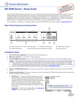
DTP RJ-45 connector — Connect the transmitter DTP Out port to the DTP In port on the receiver. Extron
recommends that you terminate both cable ends in accordance with the following specications, at a
minimum:
TIA/EIA T 568B Shielded cable
24 AWG, solid conductor
ATTENTION: Do not connect this device to a computer data or telecommunications network.
Signal LED — Lights when the unit is outputting a TMDS clock signal on the DTP output.
Link LED — Lights when a valid link is established between the units on the DTP cable.
Remote control
G
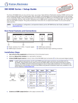
Remote Contact port — If desired, for contact closure control, plug a locally-contructed contact closure control device into this
3.5 mm, 4-pole captive screw port. Momentarily short the pin for the desired input (1, 2, or 3) to G to select that input. To force an
input to be always selected, leave the short in place.
NOTES:
Contact closure control overrides front panel input selections.
For contact closure control, auto-input switching mode must be off (see Selecting the switch mode on the next page).
H
Remote Tally port — If desired, to remotely identify the currently selected input, plug a locally-constructed device into this 3.5 mm,
4-pole captive screw connector. Connect the power wire for the device into the +V pin and connect the ground wire for each indicator
into the corresponding tally output pin: 1, 2, or 3.
When an input is selected, by either contact closure or front panel selection, the corresponding tally output pin shorts to ground,
closing the circuit and lighting the connected indicator (LED).
I
Remote RS-232 port — Plug a serial RS-232 device into the switching transmitter via this
rear panel 3.5 mm, 3-pole captive screw connector for remote control of the switching
transmitter.
Reset button
J
Reset button — This button initiates two levels of reset. For different reset levels, use an
Extron Tweeker or small screwdriver to press and hold the recessed button while the switcher
is running or while applying power. See the DTP T USW 233 User Guide, available at
www.extron.com, for details.
Power
K
Power connector — Connect an IEC power cord between the included 12 VDC
power supply and a 100-240 VAC, 50-60 Hz source. Connect the power supply to
either unit, transmitter or receiver, as shown at right. Use the included tie-wrap to
strap the cord to the captive screw connector.
NOTE: Only one power supply is required. A single power supply connected to
either unit in the Tx/Rx pair powers both units. A power supply is included
with the transmitter.
Front panel Configuration port
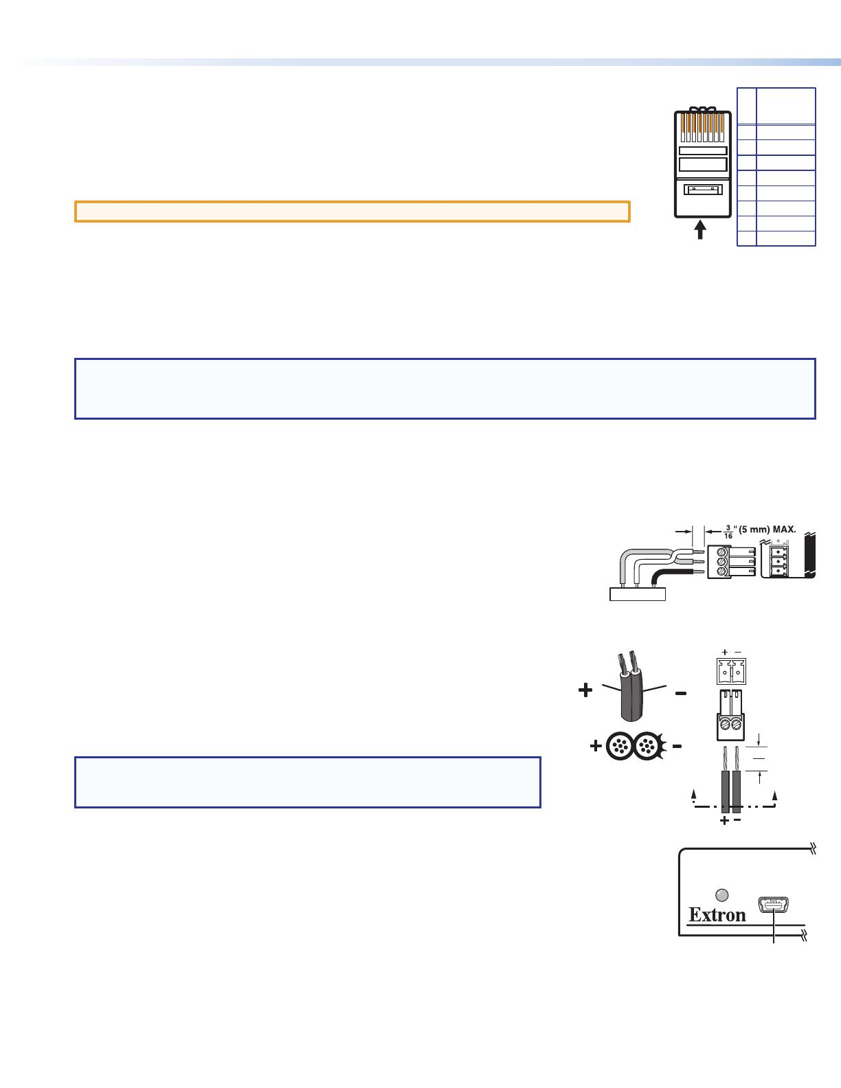
A
Configuration port — Plug a PC or other controlling device into the switching transmitter via this front
panel mini-USB connector for remote conguration of the switching transmitter.
Power Supply
Output Cord
Ridges
Smooth
Captive
Screw
Connector
3"
16 (5 mm) Max.
SECTION A–A
AA
REMOTE
RxTx Gnd
RS-232 Device
GRxTx
RS-232
V
AUTO
SWITCH
CONFIG
AA
5
Pin
1
2
3
6
7
8
4
Wire color
White-green
Green
White-orange
White-blue
Orange
White-brown
Brown
Blue
TIA/EIA T
568B
TP Wires
12345678
Pins:
3
1
23
MODE
NORMAL
AUTO
Press the button.
The LED lights
green.
1 23
MODE
NORMAL
AUTO
AUTO
SWITCH
Press and HOLD the Mode button
and either the Auto or Normal button.
Release the buttons.
A
uto Switch lights (auto)
or goes out (normal).
5
seconds
1
23
MODE
NORMAL
AUTO
Press the and
HOLD
the all three Input buttons.
All three LEDs flash three times. Release the Input buttons.
HDCP
123
3
33
11
55
44
22
Operation
Switching inputs
Select the desired input by pressing the associated input button. Observe that the
LED for the selected input lights.
NOTE: The switcher must be in normal (manual) mode (see below).
Selecting the switch mode
In auto-input switching mode, the switcher selects to the
highest numbered input with a sync signal present. Turn
auto-input switching mode on and off as follows:
1. Press and hold the Mode (Input 1) button and the
button below for the desired mode for approximately
5 seconds:
Auto (Input 3) — The Auto Switch LED lights.
Normal (Input 2) — The Auto Switch Active LED goes off.
2. Release the buttons.
Locking and unlocking the front panel (Executive mode)
The switcher has a front panel lock feature that locks the front panel. If you try to make
front panel input selections when the panel is locked, all front panel LEDs ash three
times. Toggle the front panel lock on and off by pushing and holding all three Input
buttons simultaneously for 5 seconds. All front panel LEDs ash three times.
Release the buttons.
Interpreting the Status LEDs
Signal LEDs (1 through 3) —Indicate that the switcher detects horizontal sync
(Signal LED 1) or TMDS clock (Signal LED 2 and Signal LED 3) signals on the associated input.
HDCP LEDs (2 and 3) —Indicate that the corresponding input signal is HDCP encrypted.
LockIt
®
Lacing Brackets
Use the included LockIt Lacing Brackets to securely fasten both HDMI cables as follows.
1. Plug the HDMI cable into the panel connection (
1
).
2. Loosen the HDMI connection mounting screw from the panel enough to allow the LockIt lacing
bracket to be placed over it (
2
). The screw does not have to be removed.
3. Place the LockIt lacing bracket on the screw and against the HDMI connector, then tighten the
screw to secure the bracket (
3
).
ATTENTION: Do not overtighten the HDMI connector mounting screw. The shield it fastens to
is very thin and can easily be stripped.
4. Loosely place the included tie wrap around the HDMI connector and the LockIt lacing bracket as
shown (
4
).
5. While holding the connector securely against the lacing bracket, use pliers or similar tools to
tighten the tie wrap, then remove any excess length (
5
).
4
68-2490-50
Rev. C
11 15
Extron Headquarters
+800.633.9876 Inside USA/Canada Only
Extron USA - West Extron USA - East
+1.714.491.1500 +1.919.850.1000
+1.714.491.1517 FAX +1.919.850.1001 FAX
Extron Europe
+800.3987.6673
Inside Europe Only
+31.33.453.4040
+31.33.453.4050 FAX
Extron Asia
+65.6383.4400
+65.6383.4664 FAX
Extron Japan
+81.3.3511.7655
+81.3.3511.7656 FAX
Extron China
+86.21.3760.1568
+86.21.3760.1566 FAX
Extron Middle East
+971.4.299.1800
+971.4.299.1880 FAX
Extron Korea
+82.2.3444.1571
+82.2.3444.1575 FAX
Extron India
1800.3070.3777
(Inside India Only)
+91.80.3055.3777
+91.80.3055.3737 FAX
© 2015 Extron Electronics All rights reserved. All trademarks mentioned are the property of their respective owners. www.extron.com
Application Diagram
Figure 1. Typical Switching Transmitter Application
AUTO SW
CONFIG
IR OUT
HDMI IN
AUDIO IN
S
G
HDCP
1
HDMI IN
AUDIO IN
HDCP
1
2
TLP 1000
TV
IPCP 505
IN1608
DTP HDMI 230 Rx
Projector
100-240V ~ -- A MAX
1
2
CONFIGURABLE
HDMI
HDMI
5
7
8
C
RS-232 IR
RS-232IR
Tx Rx Tx RxG
Tx Rx Tx RxG
Tx Rx Tx RxG
HDMI
A
B
3
INPUTS
OUTPUTS
Tx Rx
RS-232
G
LAN
2x25W(8Ω)/2x50W(4Ω)
RESET
AUDIO INPUTS
OUTPUTS
REMOTE
LL1R R
L2
R
L
3
R
CLASS 2 WIRING
L4
R
L5R
+48V
+48V
12
LR
VARIABLE
IN1608 SA
2
MIC/LINE
L6
R
SIG LINK
DTP IN
SIG LINK
DTP IN
SIG LINK
DTP OUT
50/60 Hz
RS-232IR
OVER DTP
OVER DTP
OVER DTP
AMPLIFIED OUTPUT
VOLUME
SCALING PRESENTATION SWITCHER
IN1608
INPUTS
1
HDCP
SIGNAL
OUTPUTS
ENTER
MENU
Extron
2 3 4 5 6 7 8 A B C
INPUTS
1 2 3 4 5 6 7 8
CONFIG
Ext
ron
DTP T U
SW 233
Tr
ansmitter
Extron
DTP T HWP 232 D Tx
Transmitter
Ethernet
Network
LR
POWER
12V
0.7A MAX
AUDIO
SIG LINK
DTP IN
OUTPUTS
XTP DTP 24 Cable
230'
230'
230'
HDMI
12345678
100
LINK
ACT
COM
IR/S
TX
RX
TX
RX
RTS
CTS
R
5
1
6
2
7
3
8
4
RELAY
FLEX
I/O
5
1
6
2
3
1
4
2
eBUS
ACT LIMIT
OVER
SWITCHED
12VDC
3
1
4
OVER
2
LIMIT
IR
7
3
8
4
IPCP 505
I
N1
608
Tx
Rx
G
DTPIN
5
0
/
60 H
z
E
xtron
D
TP T U
S
W 233
T
ransmitter
XTPDTP 24 Cabl
e
2
230
'
AUTO
SWITCH
DTP T USW 233
1
2 3
CONFIG
231
STATUS
SIGNAL
HDCP
1 / 1

Extron DTP T USW 233 User manual

Category
Video switches
Type
User manual

Ask a question and I''ll find the answer in the document

Finding information in a document is now easier with AI

Ask the document