
© Copyright 2016 ABB, All rights reserved
User manual
Battery cabinet
for PowerValue 11/31T

Modifications reserved
Page 2/30
Document information
File name
:
4NWP101805R0001_OPM_ABB_PVA11-31-T_BAT_CAB_EN_REV-B.docx
Model
:
Battery cabinet PowerValue 11/31T-96
Date of issue
: 16.11.2016
Article number : 4NWP100119R0002
Document number
: 4NWD003001
Revision : B
Foreword
This user manual contains guidelines to install the battery cabinet and it is intended for people who plan the
installation, install, commission and use or service the battery cabinet. The reader is expected to know the
fundamentals of electricity, wiring, electrical components and electrical schematic symbols
This manual contains important instructions that should be followed during installation and operation of the
battery cabinet. This product is designed for commercial / industrial use only, with UPS systems. It is not
intended for use with life support and other designated critical devices.
The battery cabinet has been designed for 12VDC x 9 Ah batteries within precise specifications. It’s highly
recommended to make use only of the batteries provided within the following articles:
ABB ordering code Description
4NWP100119R0003 Batt.cabinet PowerValue 11/31T-96 w/batt
4NWP100119R0004 Batt.cabinet PowerValue 11/31T-48 w/batt
ABB Power Protection SA declines any kind of responsibility in the occurrence other batteries than the
recommended ones are installed into the battery cabinet
Batteries contain dangerous substances that will
harm the environment if thrown away. If you
change the batteries yourself, call qualified
organizations for battery disposal and recycling.
COMMISSIONING AND OPERATIONS INSIDE THE
BATTERY CABINBET MUST BE PERFORMED BY A
CERTIFIED SERVICE ENGINEER FROM THE
MANUFACTURER OR FROM AN AGENT CERTIFIED BY
THE MANUFACTURER.
BY NOT FULFILLING THIS OBLIGATION, THE PRODUCT
MAY LOSE ITS WARRANTY

Modifications reserved
Page 3/30
Contents
1 Safety rules ....................................................................................................... 4
1.1 Warning notice system ................................................................................................ 4
1.2 Safety symbols ............................................................................................................. 4
1.3 Safety instructions ....................................................................................................... 4
2 Unpacking ......................................................................................................... 9
2.1 Preparation ................................................................................................................... 9
2.2 Battery trays ............................................................................................................... 11
2.3 Cabling kits ................................................................................................................. 12
3 Installation ...................................................................................................... 13
3.1 Battery cabinet shelves overview .............................................................................. 13
3.2 Battery wiring ............................................................................................................. 14
3.3 Placing batteries in the cabinet ................................................................................. 20
3.4 String creation and final wiring .................................................................................. 23
3.5 Test ............................................................................................................................. 25
4 Electrical scheme ........................................................................................... 26
5 Appendix A ..................................................................................................... 27
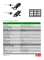
6 Technical specifications ................................................................................. 28

Modifications reserved
Page 4/30
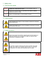
1 Safety rules
1.1 Warning notice system
1.2 Safety symbols
1.3 Safety instructions
DANGER!
WARNING!
OPERATIONS INSIDE THE BATTERY CABINET MUST BE PERFORMED BY A
SERVICE ENGINEER FROM THE MANUFACTURER OR FROM AN AGENT
CERTIFIED BY THE MANUFACTURER
DANGER!
WARNING!
THE BATTERY CABINET OPERATES WITH MAINS, BATTERY OR BYPASS
POWER THAT CARRY HIGH CURRENTS AND VOLTAGES. IT CONTAINS
COMPONENTS THAT CARRY HIGH CURRENTS AND VOLTAGES
WARNING
SEVERE INJURY AND/OR SERIOUS DAMAGE TO THE SYSTEM WILL RESULT IF
PROPER PRECAUTIONS ARE NOT TAKEN
CAUTION
MINOR INJURY AND/OR DAMAGE TO THE PRODUCT MAY RESULT IF PROPER
PREACAUTIONS ARE NOT TAKEN
NOTE REFER TO THE USER MANUAL TO AVOID PROPERTY DAMAGE
SAFETY WARNING: THIS SYMBOL IS USED TO WARN THE USER ABOUT WARNINGS,
CAUTIONS AND NOTES
DANGER: THIS SYMBOL IS USED IN THE OCCURRENCE OF ELECTRICAL LIVE PARTS
WITH HAZARDOUS VOLTAGE

Modifications reserved
Page 5/30
DANGER!
WARNING!
KEEP OUT OF BATTERY POLES WHICH CONTAIN DANGEROUS DC-VOLTAGES
CAUSING FATAL ACCIDENTS
DANGER!
WARNING!
THE BATTERIES POSITIVE AND NEGATIVE ELECTRODES SHALL NOT
TOUCH METAL; PLACE BATTERIES ON NOT METALLIC SURFACES IN
ORDER TO AVOID ANY SHORT CIRCUIT HAZARD
DANGER!
WARNING!
A BATTERY CAN PRESENT A RISK OF ELECTRICAL SHOCK AND HIGH SHORT
CIRCUIT CURRENT. THE FOLLOWING PRECAUTIONS SHOULD BE OBSERVED
WHEN WORKING ON BATTERIES:
• REMOVE WATCHES, RINGS OR OTHER METAL OBJECTS
• MAKE USE OF PROPER PPE (PERSONAL PROTECTION EQUIPMENT) AS
PER LOCAL POLICIES AND RULES
WEAR FLAME/ARC RESISTANT WHOLE BODY CLOTHING
WEAR SUITABLE VOLTAGE RATED GLOVES
USE SAFETY DIELECTRIC FOOTWEAR
WEAR ARC FLASH FACE SHIELD
USE VOLTAGE RATED TOOLS
• DO NOT LAY TOOLS OR METAL PARTS ON TOP OF BATTERIES
• DISCONNECT THE CHARGING SOURCE PRIOR TO CONNECTING OR
DISCONNECTING BATTERY TERMINALS
DANGER!
WARNING!
THE BATTERY CABINET MUST BE GROUNDED TO EARTH AND IP 20 RATED
AGAINST ELECTRICAL SHOCK AND FOREIGN OBJECTS

Modifications reserved
Page 6/30
DANGER!
WARNING!
DETERMINE IF BATTERY IS INADVERTENTLY GROUNDED. IF INADVERTENTLY
GROUNDED, REMOVE SOURCE FROM GROUND. CONTACT WITH ANY PART
OF A GROUNDED BATTERY CAN RESULT IN ELECTRAL SHOCK. THE
LIKELIHOOD OF SUCH SHOCK CAN BE REDUCED IF SUCH GROUNDS ARE
REMOVED DURING INSTALLATION AND MAINTENANCE (APPLICABLE TO
EQUIPMENT AND REMOTE BATTERY SUPPLIES NOT HAVING GROUNDED
SUPPLY CIRCUIT)
DANGER!
WARNING!
PARALLEL BATTERY CABINETS OR UPS INTERNAL BATTERIES MAY PRESENT
VOLTAGE AT TERMINALS OF A BATTERY CABINET UNDER SERVICE. MAKE
CERTAIN ALL POLES OF THE BATTERY CABINET DISCONNECTION DEVICES
ARE OPEN BEFORE UNDERTAKING INTERNAL SERVICE ACTIVITY
DANGER!
WARNING!
MAKE CERTAIN ALL DISCONNECTION DEVICES OF INSTALLED BATTERIES
ARE OPEN BEFORE CONNECTING OR DISCONNECTING AN ADDITIONAL
BATTERY CABINET TO THE BATTERY VOLTAGE BUS
DANGER!
WARNING!
RISK OF EXPLOSION IF USING AN INCORRECT BATTERY TYPE

Modifications reserved
Page 7/30
DANGER!
WARNING!
DO NOT DISPOSE OF BATTERIES IN A FIRE. THE BATTERY MAY EXPLODE
DANGER!
WARNING!
DO NOT OPEN OR MUTILATE BATTERIES. RELEASED ELECTROLYTE IS
HARMFUL TO THE SKIN AND EYES. IT MAY BE TOXIC
CAUTION!
DO NOT EXCEED BATTERY CABINETS OR UPS RATING LABELS
CAUTION!
THE BATTERY CABINET AND THE BATTERIES ARE HEAVY AND MAY TIP
DURING TRANSPORTATION IF UNPACKING INSTRUCTIONS ARE NOT
CLOSELY FOLLOWED
CAUTION!
SEALED BATTERIES MUST NEVER BE STORED IN A DISCHARGED OR
PARTIALLY DISCHARGED STATE
CAUTION!
EXTREME TEMPERATURE, UNDER- AND OVERCHARGE AND OVERDISCHARGE
WILL DESTROY BATTERIES

Modifications reserved
Page 8/30
NOTE!
AS THE BATTERY LIFE DEPENDS ON THE AMBIENT TEMPERATURE, FOR THE
UPS SYSTEM IT IS RECOMMENDED TO HAVE A LOCATION WITH CLIMATE-
CONTROLLING SYSTEM
NOTE!
TO ENSURE AN OPTIMUM OPERATION OF THE UPS SYSTEM AND A
CONTINUOUS AND EFFICIENT PROTECTION OF THE CONNECTED LOAD IT IS
RECOMMENDED TO CHECK THE BATTERIES EVERY 12 MONTHS

Modifications reserved
Page 9/30
2 Unpacking
Upon receiving the battery cabinet, carefully examine the packing container for any sign of physical
damage. In case of damage, notify immediately the carrier.
The packing container of the battery cabinet protects it from mechanical and environmental damage.
Preserve the packaging for later re-use.
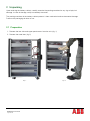
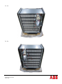
2.1 Preparation
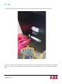
1. Remove the two side and upper panel covers from the unit. (fig. 1)
2. Remove the metal bars (fig. 2)
Fig. 1
Fig. 2

Modifications reserved
Page 10/30
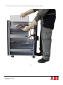
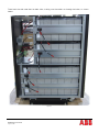
3. Extract the battery plastic trays and the two packages with cables (fig.3)
Fig. 3

Modifications reserved
Page 11/30
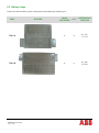
2.2 Battery trays
Check the internal battery plastic correspond to the following unpacking list:
TRAY PICTURE
NR.OF
BATTERIES
Q.TY
DESTINATION
SHELVES
TRAY A
6 8
C1..C4 /
D1..D4
TRAY B
8 6
A1..A3 /
B1..B3

Modifications reserved
Page 12/30
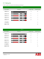
2.3 Cabling kits
Check all cables correspond to the following unpacking list:
KIT #1
Description Drawing Length (cm) Quantity (pcs)
CABLE 1-A
10 40
CABLE 1-B
27 4
CABLE 1-C
27 4
CABLE 1-D
65 4
CABLE 1-E
65 4
STICKERS
8
CABLE TIES
16
KIT #2
Description Drawing Length (cm) Quantity (pcs)
CABLE 2-A
10 42
CABLE 2-B
27 3
CABLE 2-C
27 3
CABLE 2-D
75 3
CABLE 2-E
75 3
STICKERS
6
CABLE TIES
12

Modifications reserved
Page 13/30
3 Installation
For a correct installation and cabling of the battery cabinet, please follow step by step the instructions
described below
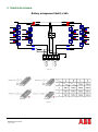
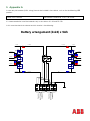
The instructions refer to the installation of the maximum amount of batteries that may fit in the battery
cabinet (96 batteries, distributed in 4x24 strings); for using 48 batteries only please refer to Appendix A
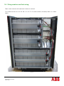
3.1 Battery cabinet shelves overview
The scheme of battery cabinet’s shelves is the following. (fig.4)
Fig. 4
A3
A2
A1
B3
B2
B1
Cabinet Back
View
C1
C2
C3
C4
D1
D2
D3
D4
TERMINALS
FUSES

Modifications reserved
Page 14/30
3.2 Battery wiring
Refer in each moment to the electrical scheme at section 3.
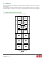
Insert 6 batteries in the trays type A and 8 batteries in the trays type B as shown in the following pictures
Fig. 5
Fig. 6

Modifications reserved
Page 15/30
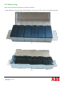
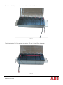
Thus, connect the batteries in each tray in series by means of cables 1-A or 2-A, as shown below:
Fig. 7
Fig. 8

Modifications reserved
Page 16/30
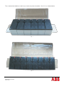
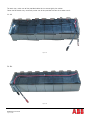
For shelves A1..A3, connect the cables 1-C or 2-C and 2-D as following:
Fig. 9
For shelves B1..B3, connect the cables 2-E and 1-B or 2-B as following:
Fig. 10

Modifications reserved
Page 17/30
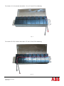
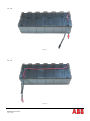
For shelves C1..C4, connect the cables 1-C or 2-C and 1-D as following:
Fig. 11
Finally, for shelves D1..D4, connect the cables 1-E and 1-B or 2-B as following:
Fig. 12

Modifications reserved
Page 18/30
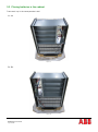
For each tray, make use of the provided cable ties to secure tightly the cables
Close the lid of each tray, eventually make use of the provided stickers for a better result:
A1..A3
Fig. 13
B1..B3
Fig. 14

Modifications reserved
Page 19/30
C1..C4
Fig. 15
D1..D4
Fig. 16

Modifications reserved
Page 20/30
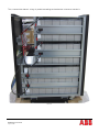
3.3 Placing batteries in the cabinet
Place each tray in the correspondent shelf
A1..A3
Fig. 17
B1..B3
Fig. 18
Page is loading ...
Page is loading ...
Page is loading ...
Page is loading ...
Page is loading ...
Page is loading ...
Page is loading ...
Page is loading ...
Page is loading ...
-
 1
1
-
 2
2
-
 3
3
-
 4
4
-
 5
5
-
 6
6
-
 7
7
-
 8
8
-
 9
9
-
 10
10
-
 11
11
-
 12
12
-
 13
13
-
 14
14
-
 15
15
-
 16
16
-
 17
17
-
 18
18
-
 19
19
-
 20
20
-
 21
21
-
 22
22
-
 23
23
-
 24
24
-
 25
25
-
 26
26
-
 27
27
-
 28
28
-
 29
29


ABB battery cabinet PowerValue 11/31 T User manual
- Type
- User manual
- This manual is also suitable for
Ask a question and I''ll find the answer in the document
Finding information in a document is now easier with AI
Related papers
-
ABB Battery cabinet for PowerValue 11-31T 10-20 kVA User manual
-
-
-
-
-
-
-
-
-
Other documents
-
Yukon 24081 User manual
-
 PowerWalker 10120174 Owner's manual
-
Toshiba 431M User manual
-
Legrand MEGALINE Specification
-
Legrand Keor MOD 200 User manual
-
Eaton E Series DX 30 kVA BI User guide
-
 BlueWalker 10120175 User guide
-
-
Alpha PN-6 Owner's manual
-
Salicru SLC-700-TWIN RT (B1) User manual

