Page is loading ...

AcquaLink
Nav Box and
System AcquaLink
Installation
Instruction
06/2016 - EN (3.0)
www.marine.vdo.com
®
®
www.marine.vdo.com

AcquaLink
®

3
Content
1. Preliminary Remarks 4
2. Safety Instructions 5
2.1 Installation 5
2.2 Preliminary Remarks 7
2.3 Safety Instructions for 7
Maintenance 7
3. The Nav Box System 8
3.1 Installation of the Nav Box 8
3.2 Data Management 9
3.3 Power Connection 10
4. Connections 11
4.1 NMEA 2000
®
12
4.2 SAE J1939 14
4.3 VDO Bus 17
4.4 VDO Sensor 19
4.5 NMEA 0183 20
4.6 Analogue Inputs 22
4.6.1 Resistive Inputs 24
4.6.2 Resistive Data Conversion 32
4.6.3 Frequency Input 34
4.6.4 Ampere Input 35
4.7 Buzzer Output 36
4.8 USB 36
4.9 Log Port 37
4.10 WMA Port 38
5. Hardware Specications 39
Content

In purchasing the VDO AcquaLink Nav
Box system you have decided on a high
value product, which has been manufac-
tured according to acknowledged techni-
cal standards. Modern production pro-
cesses and compliance with currently
applicable quality assurance standards
guarantee that our products leave the fac-
tory in perfect condition.
We thank you for making a good choice,
and we are convinced that this instrument
will be reliable and a great help to you and
keep you safe at sea.
In order to ensure easy and safe handling
of your VDO system, you should familiari-
ze yourself with all the features and func-
tions.
Please take the time to read these instruc-
tions carefully and completely.
1. Preliminary Remarks
4
Preliminary Remarks

2. Safety Instructions
ATTENTION
Please pay attention to all text
passages labeled with this sym-
bol. These are very important
hints for operating and security
of the instruments.
2.1 Installation
This product has been developed, manufactured
and tested in accordance with the requirements
of EC and UL directives and the acknowledged
state of the art.
Please follow all the instructions given in this
handbook exactly.
5
Safety Instructions

DANGER!
Explosion hazard!
Before beginning work on the en-
gine compartment of petrol engi-
nes, switch on the ventilator of the
engine compartment.
• Ensure that necessary clearance
is provided behind the cable
opening, at the position where
the gauge is to be installed.
• When selecting the installation
position for gauges or displays,
take care that no stringers
are drilled. Be careful also
of furniture, floorboards,
superstructure boxes, cables
etc.
• When carrying out installation
work with a sealing compound,
solvent vapours can be
formed. Make sure of adequate
ventilation and follow the
instructions for use of the sealing
compound manufacturer.
• Please note, that the Nav Box is
not a ISO8846 certified product
and should not be installed
inside the engine compartment.
DANGER!
Before beginning work, the
negative Terminal of the battery
should be disconnected!
• Use of information provided by
the VDO system does not release
you from the responsibility over
your ship and demands well
seamanship. Always use your
nautical experience in interpreting
the displayed values.
• If you carry out this work yourself,
wear suitable working clothes. Do
not wear wide fitting clothes. If you
have long hair, wear a hair-net.
Clothes and hair can get caught in
moving and rotating parts.
• Wearing of metallic or conductive
jewellery, such as necklaces,
bracelets, rings etc. is not allowed
when working on the electrical
installation on board.
• Please note that with
disconnection of the battery, all
volatile electronic memories lose
their input values and must be
reprogrammed.
6
Safety Instructions

The VDO Nav Box system is mainte-
nance-free. Do not use cleaning
agents.
Repairs on the system should be car-
ried out only by VDO authorized spe-
cialists !
• For the installation only use VDO
and NMEA 2000 approved cables.
• If you don’t use standard cables, the
wires used should be adequately
insulated or should have sufficient
electrical strength, and the contact
point should be protected against
electrical shock hazard. The
electrical conducting components
of the connected consuming
devices should also be protected
against direct contact through
suitable measures. Installation of
bare metallic wires and contacts is
not allowed.
• Take account of the wire cross
section. A reduction of the wire
cross section results in a higher
current density. This can cause
the wire to heat up and potentially
cause fire.
• Connect the wires only in
accordance with the wiring diagram.
2.2 Preliminary Remarks
2.3 Safety Instructions for
Maintenance
7
Safety Instructions

Please use the mounting template to
determine a proper installation loca-
tion. The Nav Box can be mounted
horizontally but it is recommended
to mount the unit vertically on a bulk-
head or other structure with the
cable connections pointing to the
bottom. This helps water to run off
and protect the cables from bending
and chafng.
You also have a better access to the
status LEDs on top of the unit.
3.1 Installation of the Nav Box
In the Box:
• Nav Box
• 3 pin power cable
• 26 pin cable for analogue input
• Mounting screws
• Installation instruction
• Mouting template
• Operation manual
• 3x VDO Bus terminators
The Nav Box is the heart of the VDO
AcquaLink system. To operate the
AcquaLink system you need the Nav
Box, at least one AcquaLink 4.3’’TFT
and one Nav Control. The sytem can
be accomplished with 110mm and
52mm gauges and a wide array of
sensors and transducers.
Additionally the Nav Box converts
SAE J1939 and analogue signals to
NMEA 2000.
In order to program and adjust the
system you need to refer to the
NavBox operation manual. This inst-
ruction focuses on the installation
and the connection of the NavBox to
optional sensors and transducers.
3. The Nav Box System
8
The Nav Box System

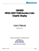
Position
Description
1 Mounting screw holes (Use all four screws to secu-
rely install the unit)
2 Status LEDs
3 Protection shield (protects connectors, offers addi-
tionally water spray protection)
1
1
3
2
1
1
The Nav Box system supports vari-
ous data inputs. The received data is
prioritized in following order:
• Priority #1: Analogue Input
• Priority #2: NMEA 2000
• Priority #3: SAEJ 1939
• Priority #4: NMEA0183
3.2 Data Management
9
Installation of the Nav Box

3.3 Power Connection
PIN No. Color Signal
1 Red Terminal 30 (Battery)
2 Black Terminal 31 (GND)
3 Yellow Terminal 15 (Ignition)
Power Connection
Position Description
1 Red
(see table "Power
Connection" for details)
2 Black
3 Yellow
4 Ribbed hose
5 Heat sink (2x)
6 Fuse 10 Amp
1
5
4
6
2
3
1
2
3
6
10
Power Connection

4. Connections
Nav Box: Connections
The NavBox features following
connection types:
Position
Description
POWER for 3 pin power cable
NMEA 2000
®
5 pin M12 Micro C
SAE J1939 1x SAE J1939 Input (5pin M12)
VDO Bus 3x VDO Bus (8 pin M12)
LOG 1 & LOG 2 2x Log Input (4 pin M12)
WMA 1x Wind Input (8 pin M12)
26 POLE AUX /
SENSOR
26 pin Analogue/NMEA0183 Input
VDO Sensor 2x CAN BusVDO Sensor Input (5 pin M12)
11
Connections

The Nav Box can be connected to an
existing NMEA 2000 system. Please
visit www.NMEA.org to nd informati-
on about NMEA 2000.
4.1 NMEA 2000
®
PIN No. Signal
1 Shield
2 NET-S (V+)
3 NET-C (V−)
4 NET-H (CAN H)
5 NET-L (CAN L)
Instrument LEN
Nav Box 3
Nav Control 4
110 mm Gauge 4
52 mm Gauge 2
4.3‘‘ TFT 12
For NMEA 2000 voltage drop calculations
please refer to this LEN list:
NMEA 2000 Pinout
12
NMEA 2000

The Nav Box can receive and transmit
NMEA 2000 data. It can also convert
analogue, NMEA 0183 and SAE J1939.
It supports the reception of following
NMEA 2000 PGNs:
PGN HEX Message Name
59904 00EA00 ISO Request
60928 00EE00 ISO Address Claim
65281 00FF01 VDO Bus Proprietary Single-Frame Message
(End Of Line)
60416 00EC00 ISO Transport Protocol, Connection Manage-
ment - RTS group function
60160 00EB00 ISO Transport Protocol, Data Transfer
59392 00E800 ISO Acknowledgment
126208 01ED00 NMEA - Request group function
130306 01FD02 Wind Data
129026 01F802 COG & SOG, Rapid Update
128259 01F503 Speed, Water Referenced
128267 01F50B Water Depth
129025 01F801 Position, Rapid Update
129033 01F809 Local Time Offset
127250 01F112 Vessel Heading
127489 01F201 Engine Parameters, Dynamic
127488 01F200 Engine Parameters, Rapid Update
130312 01FD08 Temperature - DEPRECATED
130314 01FD0A Actual Pressure
127251 01F113 Rate of Turn
127257 01F119 Attitude
130310 01FD06 Environmental Parameters - DEPRECATED
130311 01FD07 Environmental Parameters- DEPRECATED
127245 01F10D Rudder
13
NMEA 2000

In case multiple instances of the same
value are received from the NMEA
2000 network, the Nav Box has
following priorities:
• For Time Data:
1 - " System Time "
2 - "Local Time Offset"
• For Barometric Date:
1 - "ActualPressure"
2 - "EnvironmentalParameters2"
3 - "EnvironmentalParameters"
• For Temperature Data:
1 - "Temperature_Ext"
2 - "Temperature"
3 - "EnvironmentalParameters2"
4 - "EnvironmentalParameters"
In general, if one message contains an
error value, the next one is considered.
NMEA 2000 Engine Support
The Nav Box system supports up to
four NMEA 2000 engines. The engines
have to be properly programmed with
individual instance numbers (0-3) by
an engine technician.
Please refer to the Operation manual
to set up the Tachometers with the
right instance numbers.
4.2 SAE J1939
SAE J1939 Pinout
PGN HEX Message Name
127505 01F211 Fluid Level
127493 01F205 Transmission Parameters, Dynamic
126992 01F010 System Time
130316 01FD0C Temperature, Extended Range
129283 01F903 Cross Track Error
129284 01F904 Navigation Data
127508 01F214 Battery Status
129291 01F90B Set & Drift, Rapid Update
For transmitting PGNs please refer to Chapter “SAE J1939” and Analogue Inputs.
14
SAE J1939

PIN No. Signal
1 Shield (internally not connected)
2 Ignition (internally connected to battery when
system is ON)
3 GND
4 CAN H
5 CAN L
The Nav Box has three SAE J1939 connec-
tions:
Four Engines in one CAN Bus system
The NavBox supports up to four SAE
J1939 engines if they are in the same
CAN Bus network system and have
different source addresses (0-3).
SAE J1939 Installation
The Nav Box supports one SAE J1939
engine connection. .
SAEJ1939 Multi Engine support
Data Handling
The Nav Box has an interface that is
SAE J1939 compatible. It is used to re-
ceive en gine data and distributes them
over VDO Bus and NMEA 2000 to make
them available for both the NMEA2000
network and the AcquaLink system.
Supported SAE J1939 Messages:
SAE J1939 supported SPNs Description
PGN 61444 - SPN 190 Engine Speed
PGN 65270 - SPN 102 Engine Turbocharger Boost Pressure
PGN 65263 - SPN 100 Engine Oil Pressure
PGN 65262 - SPN 175 Engine Oil Temperature 1
PGN 65262 - SPN 110 Engine Coolant Temperature
PGN 65266 - SPN 183 Engine Fuel Rate
PGN 65253 - SPN 247 Engine Total Hours of Operation
PGN 65263 - SPN 109 Engine Coolant Pressure
Important:
If you use any of the three SAEJ1939
ports you need to terminate all three
SAE J1939 ports with three 180 ohm
resistors!
VDO offers an optional 180 ohm inline
terminator (A2C99794200).
15
SAEJ1939 Installation

SAE J1939 supported SPNs Description
PGN 65276 - SPN 96 Fuel Level
PGN 65270 - SPN 173 Exhaust Gas Temperature
PGN 65269 - SPN 108 Barometric Pressure
PGN 65269 - SPN 171 Ambient Air Temperature
PGN 65272 - SPN 127 Transmission Oil Pressure
PGN 65272 - SPN 177 Transmission Oil Temperature
PGN 65279 - SPN 97 Water in Fuel Indicator
The Nav Box distributes the received
SAEJ1939 data to the NMEA 2000 net-
work.
SAEJ1939 Input Data NMEA 2000 output
Engine Speed (RPM) 127488 Eng. Parameters, Rapid Update
Boost Pressure 127488 Eng. Parameters, Rapid Update
Engine Oil Pressure 127489 Eng. Parameters, Dynamic
Engine Oil Temperature 1 127489 Eng. Parameters, Dynamic
Engine Coolant Temperature 127489 Eng. Parameters, Dynamic
Engine Fuel Rate 127489 Eng. Parameters, Dynamic
Engine Total Hours of Operation 127489 Eng. Parameters, Dynamic
Engine Coolant Pressure 127489 Eng. Parameters, Dynamic
Fuel Level 127505 Fluid Level
Exhaust Gas Temperature 130316 Temperature Ext
Barometric Pressure 130314 Actual Pressure
Ambient Air Temperature 130316 Temperature Ext
Transmission Oil Pressure 127493 Trans. Parameter Dynamic
Transmission Oil Temperature 127493 Trans. Parameter Dynamic
Following data is converted and
transmitted:
The Nav Box also receives all
DM1 DTC messages of the SPN List
above.
16
Data Handling

4.3 VDO Bus
PIN No. Signal
1 Ignition / Terminal 15
2 GND / Terminal 31
3 Battery + / Terminal 30
4 CAN H
5 CAN L
6 Shield
7 Ignition / Terminal 15
8 GND / Terminal 31
VDO Bus Pinout
The VDO Bus is an NMEA2000-based
communication used within the Acqua-
link system to share the information
gathered from the system interfaces as
well as to distribute proprietary messa-
ges containing status information of the
system itself. The VDO Bus uses M12 8
Pin cables and all devices are powered
through the network.
The NavBox has three VDO Bus ports,
so three separate VDO Bus segments
can be installed. This helps to reduce
the power drop in the system and al-
lows an easy installation in all areas of
the vessel.
Every 110mm gauge, 4.3’’ TFT
and Nav Control features two
equal VDO Bus connectors in the
rear.
The units are daisy chained to-
gether.
17
VDO Bus

Important:
• All three VDO Bus segments have to
be terminated with a VDO Terminator
(included in box).
• If you haven’t connected an
instrument or Nav Control to
a Nav Box port, connect the
terminator directly to the not used
NavBox VDO port.
• If you have connected displays or
gauges, use the terminator on last
empty VDO port on the last unit in
the chain.
• There mustn't be any empty
connector
Note:
VDO Bus cables have two female con-
nectors. In order to extent the cable
length an optional gender changer
connector is needed (A2C38805500).
VDO Bus Limitations
The NavBox provides power to all the
110mm gauges and 4.3’’ TFTs connec-
ted to the system. Due to the power
consumption and the resistance of the
cables, there are limitations of the ma-
ximum cable length and number of
possible instruments in the system.
In order to have a properly working
system the voltage drop of every of the
three VDO Bus segments have to be
calculated.
1 LEN = 0.05 Ampere
Instrument LEN
NavBox 3
NavControl 4
110 mm Gauge 4
52 mm Gauge 2
4.3‘‘ TFT 12
LEN List for VDO Products:
18
VDO Bus

Calculation
12V power supply:
The voltage drop for every segment of
the VDO Bus is calculated as follow:
Ohm‘s Law: E (voltage drop) = I (circuit
current) x R (wire resistance)
R = 2/2x Cable Length (m) x Power
Pair Resistance / 100
I = LEN (Load Equivalency Number) x
0.050 amps
L = Total length of VDO Bus cables in
one segment
-> E = 0.05 x LEN x L x 0.057
The voltage drop for each VDO Bus
Segment shouldn’t be higher than 3V
Note:
VDO Bus has 2x AWG 22 Power/
Ground cables -> so there is different
voltage drop calculation than NMEA
2000.
24V power supply:
If using a 24V system the voltage drop
may not be higher than 9V.
Note:
The maximum Number of LEN in the
NavBox system is 120 equals 6 Am-
pere.
4.4 VDO Sensor
You can connect the VDO Navsensor
and VDO NMEA 2000 Windsensor di-
rectly to the NavBox without using the
NMEA 2000 Network
Note:
One 120ohm resistor has to be ins-
talled as close as possible to the sen-
sor.
19
Calculation

4.5 NMEA 0183
The NavBox can receive NMEA 0183
data and distributes it over VDO Bus
and NMEA2000 to make them availa-
ble for both the AcquaLink system and
the NMEA 2000 network.
The NavBox supports following NMEA
0183 sentences:
NMEA 0183 supported sentences Description
RMC Recommended Minimum Navigation
Information
MTW Sea-Water temperature
DBT Depth Below Transducer
VHW Water Speed and Heading
VTG Track Made Good and Ground Speed
XTE Cross-Track Error, Measured
MWV Wind Speed and Angle
HDM Heading - Magnetic
HDG Heading - Deviation & Variation
BWC Bearing and Distance to Waypoint, Latitu-
de, N/S, Longitude, E/W, UTC, Status
20
NMEA 0183
/