Page is loading ...

IMB-Q670 Micro-ATX Motherboard
Page i
IEI Technology Corp.
User Manual
MODEL:
IMB-Q670
Micro-ATX LGA1155 Motherboard for Intel® Core™ i7/i5/i3
Quad/Dual core CPU, Intel® Q67, DDR3, VGA/DVI/HDMI
Dual Intel PCIe GbE, Two USB 3.0 ports, Ten COM ports
Two SATA 6Gb/s ports, Audio and RoHS
Rev. 1.00 – April 28, 2011

IMB-Q670 Micro-ATX Motherboard
Page ii
Revision
Date Version
Changes
April 28, 2011 1.00 Initial release

IMB-Q670 Micro-ATX Motherboard
Page iii
Copyright
COPYRIGHT NOTICE
The information in this document is subject to change without prior notice in order to
improve reliability, design and function and does not represent a commitment on the part
of the manufacturer.
In no event will the manufacturer be liable for direct, indirect, special, incidental, or
consequential damages arising out of the use or inability to use the product or
documentation, even if advised of the possibility of such damages.
This document contains proprietary information protected by copyright. All rights are
reserved. No part of this manual may be reproduced by any mechanical, electronic, or
other means in any form without prior written permission of the manufacturer.
TRADEMARKS
All registered trademarks and product names mentioned herein are used for identification
purposes only and may be trademarks and/or registered trademarks of their respective
owners.

IMB-Q670 Micro-ATX Motherboard
Page iv
Table of Contents
1 INTRODUCTION.......................................................................................................... 1
1.1 INTRODUCTION........................................................................................................... 2
1.2 BENEFITS ................................................................................................................... 2
1.3 FEATURES................................................................................................................... 3
1.4 CONNECTORS ............................................................................................................. 4
1.5 DIMENSIONS............................................................................................................... 5
1.6 DATA FLOW................................................................................................................ 6
1.7 TECHNICAL SPECIFICATIONS ...................................................................................... 7
2 PACKING LIST............................................................................................................. 9
2.1 ANTI-STATIC PRECAUTIONS...................................................................................... 10
2.2 UNPACKING PRECAUTIONS....................................................................................... 10
2.3 PACKING LIST............................................................................................................11
2.4 OPTIONAL ITEMS...................................................................................................... 12
3 CONNECTORS ........................................................................................................... 14
3.1 PERIPHERAL INTERFACE CONNECTORS..................................................................... 15
3.1.1 IMB-Q670 Layout............................................................................................ 15
3.1.2 Peripheral Interface Connectors ..................................................................... 15
3.1.3 External Interface Panel Connectors............................................................... 16
3.2 INTERNAL PERIPHERAL CONNECTORS...................................................................... 17
3.2.1 ATX Power Connector ..................................................................................... 17
3.2.2 Battery Connector............................................................................................ 18
3.2.3 CPU Fan Connector........................................................................................ 19
3.2.4 CPU Power Connector.................................................................................... 20
3.2.5 Digital I/O Connector...................................................................................... 21
3.2.6 Front Panel Audio Connector.......................................................................... 22
3.2.7 Front Panel Connector .................................................................................... 23
3.2.8 FW Programming............................................................................................. 24
3.2.9 Infrared Interface Connector........................................................................... 25
3.2.10 Memory Card Slot.......................................................................................... 26

IMB-Q670 Micro-ATX Motherboard
Page v
3.2.11 PCH Fan Connector....................................................................................... 27
3.2.12 PCI Express Power........................................................................................ 28
3.2.13 SATA 3Gb/s Drive Connector ........................................................................ 29
3.2.14 SATA 6Gb/s Drive Connector ........................................................................ 30
3.2.15 Serial Port Connector, RS-422/485................................................................ 31
3.2.16 Serial Port Connectors, RS-232..................................................................... 32
3.2.17 SMBus Connector .......................................................................................... 34
3.2.18 SPDIF Connector........................................................................................... 35
3.2.19 SPI Connector................................................................................................ 36
3.2.20 System Fan Connector................................................................................... 36
3.2.21 TPM Connector.............................................................................................. 37
3.2.22 USB Connectors............................................................................................. 38
3.3 EXTERNAL PERIPHERAL INTERFACE CONNECTOR PANEL ......................................... 40
3.3.1 Audio Connector .............................................................................................. 40
3.3.2 Keyboard/Mouse Connector ............................................................................ 41
3.3.3 Ethernet and USB Connector........................................................................... 41
3.3.4 HDMI Port Connector..................................................................................... 42
3.3.5 Serial Port Connectors (COM1)...................................................................... 43
3.3.6 VGA and DVI Connector ................................................................................. 44
4 INSTALLATION ......................................................................................................... 46
4.1 ANTI-STATIC PRECAUTIONS...................................................................................... 47
4.2 INSTALLATION CONSIDERATIONS.............................................................................. 47
4.2.1 Socket LGA1155 CPU Installation .................................................................. 49
4.2.2 Socket LGA1155 Cooling Kit Installation........................................................ 52
4.2.3 DIMM Installation........................................................................................... 54
4.3 JUMPER SETTINGS .................................................................................................... 55
4.3.1 AT/ATX Power Mode Jumper (by active hardware) ........................................ 55
4.3.2 Clear CMOS Jumper........................................................................................ 56
4.3.3 ME Debug Connector...................................................................................... 57
4.3.4 USB Power Select Jumper............................................................................... 58
4.3.5 Wake-on LAN Jumper ...................................................................................... 58
4.4 INTERNAL PERIPHERAL DEVICE CONNECTIONS........................................................ 59
4.4.1 SATA Drive Connection ................................................................................... 59
4.5 EXTERNAL PERIPHERAL INTERFACE CONNECTION ................................................... 61

IMB-Q670 Micro-ATX Motherboard
Page vi
4.5.1 Audio Connector .............................................................................................. 61
4.5.2 LAN Connection............................................................................................... 62
4.5.3 Parallel Device Connection............................................................................. 63
4.5.4 PS/2 Keyboard and Mouse Connection ........................................................... 64
4.5.5 Serial Device Connection ................................................................................ 65
4.5.6 USB Connection (Dual Connector)................................................................. 66
4.5.7 VGA Monitor Connection ................................................................................ 67
4.6 SOFTWARE INSTALLATION ........................................................................................ 68
5 BIOS.............................................................................................................................. 71
5.1 INTRODUCTION......................................................................................................... 72
5.1.1 Starting Setup................................................................................................... 72
5.1.2 Using Setup...................................................................................................... 72
5.1.3 Getting Help..................................................................................................... 73
5.1.4 Unable to Reboot after Configuration Changes.............................................. 73
5.1.5 BIOS Menu Bar................................................................................................ 73
5.2 MAIN........................................................................................................................ 74
5.3 ADVANCED............................................................................................................... 75
5.3.1 ACPI Settings................................................................................................... 76
5.3.2 Trusted Computing........................................................................................... 77
5.3.3 CPU Configuration.......................................................................................... 78
5.3.3.1 CPU Information....................................................................................... 79
5.3.4 SATA Configuration ......................................................................................... 80
5.3.5 Intel TXT(LT) Configuration............................................................................ 81
5.3.6 USB Configuration........................................................................................... 82
5.3.7 Super IO Configuration ................................................................................... 84
5.3.7.1 Serial Port n Configuration....................................................................... 85
5.3.8 H/W Monitor.................................................................................................... 90
5.3.8.1 FAN 1 Configuration ................................................................................ 92
5.3.8.2 FAN 2 Configuration ................................................................................ 93
5.3.9 Secondary Super IO Configuration ................................................................. 95
5.3.9.1 Serial Port 7 Configuration....................................................................... 96
5.3.9.2 Serial Port 8 Configuration....................................................................... 97
5.3.9.3 Serial Port 9 Configuration....................................................................... 97
5.3.9.4 Serial Port 10 Configuration..................................................................... 98

IMB-Q670 Micro-ATX Motherboard
Page vii
5.3.10 Serial Port Console Redirection .................................................................... 99
5.4 CHIPSET ................................................................................................................. 101
5.4.1 Northbridge Configuration............................................................................ 103
5.4.2 Southbridge Configuration ............................................................................ 105
5.4.3 Integrated Graphics....................................................................................... 109
5.4.4 ME Subsystem.................................................................................................110
5.4.4.1 AMT Configuration..................................................................................111
5.5 BOOT.......................................................................................................................113
5.6 SECURITY................................................................................................................114
5.7 EXIT........................................................................................................................115
A BIOS OPTIONS .........................................................................................................117
B TERMINOLOGY...................................................................................................... 121
C DIGITAL I/O INTERFACE..................................................................................... 125
C.1 INTRODUCTION...................................................................................................... 126
C.2 DIO CONNECTOR PINOUTS.................................................................................... 126
C.3 ASSEMBLY LANGUAGE SAMPLES........................................................................... 126
C.3.1 Enable the DIO Input Function..................................................................... 126
C.3.2 Enable the DIO Output Function.................................................................. 127
D WATCHDOG TIMER .............................................................................................. 128
E COMPATIBILITY.................................................................................................... 131
E.1 COMPATIBLE OPERATING SYSTEMS........................................................................ 132
E.2 COMPATIBLE PROCESSORS..................................................................................... 132
F HAZARDOUS MATERIALS DISCLOSURE........................................................ 133
F.1 HAZARDOUS MATERIALS DISCLOSURE TABLE FOR IPB PRODUCTS CERTIFIED AS
ROHS COMPLIANT UNDER 2002/95/EC WITHOUT MERCURY..................................... 134

IMB-Q670 Micro-ATX Motherboard
Page viii
List of Figures
Figure 1-1: IMB-Q670......................................................................................................................2
Figure 1-2: Connectors ..................................................................................................................4
Figure 1-3: IMB-Q670 Dimensions (mm) ......................................................................................5
Figure 1-4: Data Flow Diagram......................................................................................................6
Figure 3-1: Connectors and Jumpers.........................................................................................15
Figure 3-2: ATX Power Connector Pinout Location..................................................................18
Figure 3-3: Battery Connector Location.....................................................................................19
Figure 3-4: CPU Fan Connector Location..................................................................................20
Figure 3-5: CPU Power Connector Location..............................................................................21
Figure 3-6: Digital I/O Connector Location ................................................................................22
Figure 3-7: Front Panel Audio Connector Location..................................................................23
Figure 3-8: Front Panel Connector Location .............................................................................24
Figure 3-9: FW Programming Connector Location...................................................................25
Figure 3-10: Infrared Connector Location..................................................................................26
Figure 3-11: Memory Card Slot Location ...................................................................................27
Figure 3-12: PCH Fan Connector Location................................................................................28
Figure 3-13: PCIe Power Location ..............................................................................................29
Figure 3-14: SATA 3Gb/s Drive Connector Location................................................................30
Figure 3-15: SATA 6Gb/s Drive Connector Location................................................................31
Figure 3-16: Serial Port Connector Location.............................................................................32
Figure 3-17: Serial Port Connector Location.............................................................................33
Figure 3-18: SMBus Connector Location...................................................................................34
Figure 3-19: SPDIF Connector Location ....................................................................................35
Figure 3-20: SPI Connector Location .........................................................................................36
Figure 3-21: System Fan Connector Location...........................................................................37
Figure 3-22: TPM Connector Location........................................................................................38
Figure 3-23: USB Connector Pinout Locations.........................................................................39
Figure 3-24: External Peripheral Interface Connector..............................................................40
Figure 3-25: Audio Connector.....................................................................................................41
Figure 3-26: Serial Port Connector Pinouts...............................................................................44

IMB-Q670 Micro-ATX Motherboard
Page ix
Figure 3-27: VGA Connector .......................................................................................................45
Figure 4-1: Intel LGA1155 Socket ...............................................................................................49
Figure 4-2: Remove Protective Cover.........................................................................................50
Figure 4-3: CPU Socket Load Plate.............................................................................................50
Figure 4-4: Insert the Socket LGA1155 CPU..............................................................................51
Figure 4-5: Cooling Kits (CF-1156A-RS and CF-1156B-RS) .....................................................52
Figure 4-6: Securing the Heat sink to the IMB-Q670.................................................................53
Figure 4-7: DIMM Installation.......................................................................................................54
Figure 4-8: AT/ATX Power Mode Jumper Location...................................................................56
Figure 4-9: Clear BIOS Jumper Location ...................................................................................57
Figure 4-10: ME Debug Connector Location .............................................................................57
Figure 4-11: USB Power Select Jumper Location.....................................................................58
Figure 4-12: Wake-on LAN Connector Pinout Locations .........................................................59
Figure 4-13: SATA Drive Cable Connection...............................................................................60
Figure 4-14: SATA Power Drive Connection..............................................................................61
Figure 4-15: Audio Connector.....................................................................................................62
Figure 4-16: LAN Connection......................................................................................................63
Figure 4-17: Parallel Device Connector......................................................................................64
Figure 4-18: PS/2 Keyboard/Mouse Connector.........................................................................65
Figure 4-19: Serial Device Connector.........................................................................................66
Figure 4-20: USB Connector........................................................................................................67
Figure 4-21: VGA Connector .......................................................................................................68
Figure 4-22: Introduction Screen................................................................................................69
Figure 4-23: Available Drivers.....................................................................................................70

IMB-Q670 Micro-ATX Motherboard
Page x
List of Tables
Table 1-1: IMB-Q670 Specifications..............................................................................................8
Table 2-1: Packing List.................................................................................................................12
Table 2-2: Optional Items.............................................................................................................13
Table 3-1: Peripheral Interface Connectors...............................................................................16
Table 3-2: Rear Panel Connectors..............................................................................................17
Table 3-3: ATX Power Connector Pinouts .................................................................................18
Table 3-4: Battery Connector Pinouts........................................................................................19
Table 3-5: CPU Fan Connector Pinouts......................................................................................20
Table 3-6: CPU Power Connector Pinouts.................................................................................21
Table 3-7: Digital I/O Connector Pinouts....................................................................................22
Table 3-8: Front Panel Audio Connector Pinouts .....................................................................23
Table 3-9: Front Panel Connector Pinouts.................................................................................24
Table 3-10: FW Programming Connector Pinouts ....................................................................25
Table 3-11: Infrared Connector Pinouts.....................................................................................26
Table 3-12: PCH Fan Connector Pinouts ...................................................................................28
Table 3-13: PCIe Power Pinouts..................................................................................................29
Table 3-14: SATA 3Gb/s Drive Connector Pinouts....................................................................30
Table 3-15: SATA 6Gb/s Drive Connector Pinouts....................................................................31
Table 3-16: Serial Port Connector Pinouts ................................................................................32
Table 3-17: Serial Port Connector Pinouts ................................................................................34
Table 3-18: SMBus Connector Pinouts ......................................................................................35
Table 3-19: SPDIF Connector Pinouts........................................................................................35
Table 3-20: SPI Connector Pinouts.............................................................................................36
Table 3-21: System Fan Connector Pinouts..............................................................................37
Table 3-22: TPM Connector Pinouts...........................................................................................38
Table 3-23: USB Port Connector Pinouts...................................................................................39
Table 3-24: PS/2 Connector Pinouts...........................................................................................41
Table 3-25: LAN Pinouts ..............................................................................................................42
Table 3-26: USB Port Pinouts......................................................................................................42
Table 3-27: HDMI Connector Pinouts .........................................................................................43

IMB-Q670 Micro-ATX Motherboard
Page xi
Table 3-28: Serial Port Connector Pinouts ................................................................................43
Table 3-29: VGA Connector Pinouts...........................................................................................44
Table 3-30: DVI Connector Pinouts.............................................................................................45
Table 4-1: Jumpers.......................................................................................................................55
Table 4-2: AT/ATX Power Mode Jumper Settings.....................................................................56
Table 4-3: Clear BIOS Jumper Settings......................................................................................56
Table 4-4: ME Debug Connector Pinouts...................................................................................58
Table 4-5: USB Power Select Jumper Settings .........................................................................58
Table 4-6: Wake-on LAN Connector Pinouts.............................................................................59
Table 5-1: BIOS Navigation Keys................................................................................................73
Table 5-2: Digital I/O Connector Pinouts................................................................................. 126

IMB-Q670 Micro-ATX Motherboard
Page xii
BIOS Menus
BIOS Menu 1: Main.......................................................................................................................74
BIOS Menu 2: Advanced..............................................................................................................76
BIOS Menu 3: ACPI Configuration..............................................................................................76
BIOS Menu 4: TPM Configuration...............................................................................................77
BIOS Menu 5: CPU Configuration...............................................................................................78
BIOS Menu 6: CPU Configuration...............................................................................................79
BIOS Menu 7: SATA Configuration.............................................................................................80
BIOS Menu 8: Intel TXT(LT) Configuration ................................................................................82
BIOS Menu 9: USB Configuration...............................................................................................82
BIOS Menu 10: Super IO Configuration......................................................................................84
BIOS Menu 11: Serial Port n Configuration Menu.....................................................................85
BIOS Menu 12: H/W Monitor........................................................................................................91
BIOS Menu 13: FAN 1 Configuration..........................................................................................92
BIOS Menu 14: FAN 2 Configuration..........................................................................................94
BIOS Menu 15: Secondary Super IO Configuration..................................................................95
BIOS Menu 16: Serial Port Console Redirection.................................................................... 100
BIOS Menu 17: Chipset............................................................................................................. 102
BIOS Menu 18:Northbridge Chipset Configuration................................................................ 103
BIOS Menu 19: Southbridge Chipset Configuration.............................................................. 106
BIOS Menu 20: Integrated Graphics........................................................................................ 109
BIOS Menu 21: ME Subsystem................................................................................................. 111
BIOS Menu 22: AMT Configuration.......................................................................................... 112
BIOS Menu 23: Boot.................................................................................................................. 113
BIOS Menu 24: Security............................................................................................................ 114
BIOS Menu 25:Exit..................................................................................................................... 115

IMB-Q670 Micro-ATX Motherboard
Page 1
Chapter
1
1 Introduction

IMB-Q670 Micro-ATX Motherboard
Page 2
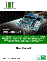
1.1 Introduction
Figure 1-1: IMB-Q670
The IMB-Q670 is a MicroATX motherboard. It accepts a Socket LGA1155 Intel® Core™
i3/i5/i7 processor and supports four 240-pin 1333/1066 MHz dual-channel DDR3 DIMM
modules up to 32.0 GB maximum. The IMB-Q670 includes a VGA, HDMI, and DVI-D port.
Expansion and I/O include one PCI slot, one PCIe x16 slot, one PCIe x4 slot, one PCIe
x16 slot with x1 signal, two USB 3.0 ports on the rear panel by NEC D720200F1, two USB
2.0 on the rear panel, eight USB 2.0 by pin header, four SATA 3Gb/s connectors, two
SATA 6Gb/s connectors, ten COM ports, and a keyboard/mouse connector.
1.2 Benefits
Some of the IMB-Q670 motherboard benefits include:
Powerful graphics with multiple monitors
Staying connected with both wired LAN connections
Speedy running of multiple programs and applications

IMB-Q670 Micro-ATX Motherboard
Page 3
1.3 Features
Some of the IMB-Q670 motherboard features are listed below:
Micro-ATX
RoHS compliant
LGA1155 CPU socket
One PCI card expansion slot
One PCIe x16 card expansion slot
One PCIe x16 card expansion slot with x1 signal
One PCIe x4 card expansion slot
Supports two dual-channel DDR3 DIMMs
One external RS-232 serial port
Eight internal RS-232 serial ports connectors
One internal RS-422/485 serial port connector
Two Intel PCIe Gigabit Ethernet connectors
Four SATA 3Gb/s connectors
Two SATA 6Gb/s connectors
High Definition audio
Intel® Q67 Chipset

IMB-Q670 Micro-ATX Motherboard
Page 4
1.4 Connectors
The connectors on the IMB-Q670 are shown in the figure below.
Figure 1-2: Connectors

IMB-Q670 Micro-ATX Motherboard
Page 5
1.5 Dimensions
The main dimensions of the IMB-Q670 are shown in the diagram below.
Figure 1-3: IMB-Q670 Dimensions (mm)


IMB-Q670 Micro-ATX Motherboard
Page 7
1.7 Technical Specifications
IMB-Q670 technical specifications are listed below.
Specification/Model IMB-Q670
Form Factor Micro-ATX
CPU Supported LGA1155 Socket Intel® Core™ i7/i5/i3 Quad/Dual core
Northbridge Chipset Intel® Q67
Integrated Graphics Supports DirectX 10.1/OpenGL 3.0
Full MPEG2, VC1, AVC Decode
Memory Four 240-pin 1333/1066 MHz Dual-Channel DDR3 SDRAM DIMMs
support up to 32.0 GB maximum
Southbridge Chipset Intel® Q67
Audio Realtek ALC888 HD Audio codec (Line-in, Line-out, Mic)
BIOS UEFI BIOS
Digital I/O 24-bit, 12-bit input/12-bit output
Ethernet Controllers Intel® 82574L/Intel® 82579 PHY with Intel® AMT 7.0 support
Super I/O Controller Fintek F81866
Watchdog Timer Software programmable supports 1~255 sec. system reset
Expansion
PCI One PCI slot
PCIe One PCIe x4 slot
One PCIe x16 slot
One PCIe x16 slot (with x1 signal)
I/O Interface Connectors
Audio Connectors One external audio jack (line-in, line-out, mic-in)
One internal front panel audio connector (2x5 pin header)
Display port One VGA Integrated in the Intel® Q67
One HDMI Integrated in the Intel® Q67
One DVI-D Integrated in the Intel® Q67

IMB-Q670 Micro-ATX Motherboard
Page 8
Specification/Model IMB-Q670
Ethernet Two RJ-45 ports
Keyboard/Mouse Dual PS/2 port
TPM 2 x 10-pin pin header
Serial Ports One external RS-232 serial port
One RS-422/485 via internal box pin headers
Eight RS-232 via internal box pin headers
USB ports Two external USB 2.0 ports on rear IO
Two external USB 3.0 ports on rear IO by NEC D720200F1
Eight internal USB 2.0 ports by pin header
Serial ATA Four SATA 3Gb/s channels with 3.0 Gb/s data transfer rates
Two SATA 6Gb/s channels with 6.0 Gb/s data transfer rates
Environmental and Power Specifications
Power Supply ATX supported
Power Consumption [email protected], [email protected] , [email protected], [email protected], [email protected]
(Intel® 2.60GHz CPU with 1333MHz DDR3 4GB x 4 Memory)
Operating temperature -20ºC ~ 60ºC/-4°F ~ 140°F
Humidity 5% ~ 95% (non-condensing)
Physical Specifications
Dimensions 244 mm x 244 mm
Weight GW/NW 1200 g / 680 g
Table 1-1: IMB-Q670 Specifications
/