Page is loading ...

1
E
N
G
L
I
S
H
7610.483.7B 5/02
Instruction Manual
Models: HPRP 25, 35, 50, 75,
100, 125, 150
Contents
GENERAL SAFETY INFORMATION ............................... 2
RECEIVING, MOVING, UNPACKING ............................. 2
1.0 INSTALLATION ...................................................... 3
2.0 OPERATION .......................................................... 5
3.0 MAINTENANCE .................................................... 6
SIZING ......................................................................... 6
ENGINEERING DATA.................................................... 7
ELECTRICAL SCHEMATICS ........................................... 8
DIMENSIONS / WEIGHTS ............................................. 9
TROUBLESHOOTING .................................................... 10
PARTS LIST .................................................................. 11
WARRANTY................................................................. 12
REFRIGERATED
TYPE
COMPRESSED
AIR DRYERS
SERVICE DEPARTMENT: (724) 746-1100
F
R
A
N
Ç
A
I
S
E
S
P
A
Ñ
O
L
®

2
E
N
G
L
I
S
H
1. PRESSURIZED DEVICES:
This equipment is a pressure containing device. Do
not exceed maximum operating pressure as shown
on equipment serial number tag. Make sure equip-
ment is depressurized before working on or disas-
sembling it for service.
GENERAL SAFETY INFORMATION
2. ELECTRICAL:
This equipment requires electricity to operate.
Install equipment in compliance with all applicable
electrical codes.
Standard equipment is supplied with electrical enclo-
sures not intended for installation in hazardous
environments.
Disconnect power supply to equipment when per-
forming any electrical service work.
A. RECEIVING
This shipment has been thoroughly checked, packed
and inspected before leaving our plant. It was re-
ceived in good condition by the carrier and was so
acknowledged.
Check for Visible Loss or Damage.
If this shipment shows evidence of loss or damage at
time of delivery to you, insist that a notation of this
loss or damage be made on the delivery receipt by
the carrier’s agent.
B. UNPACKING
Check for Concealed Loss or Damage.
When a shipment has been delivered to you in
apparent good order, but concealed damage is
found uponunpacking, notify the carrier immediately
and insist on his agent inspecting the shipment.
Concealed damage claims are not our responsibility
as our terms are F.O.B. point of shipment.
C. MOVING
In moving or transporting dryer, do not tip dryer
onto its side.
D. STORAGE
Important - Do not store dryer in temperatures
above 130°F, 54.4°C.
3. BREATHING AIR:
Air treated by this equipment may not be suitable
for breathing without further purification.
Refer to applicable standards and specifications
for the requirements for breathing quality air.
RECEIVING, MOVING, AND UNPACKING

3
E
N
G
L
I
S
H
IMPORTANT:
READ PRIOR TO STARTING THIS EQUIPMENT
1.0 Installation
1.1 Location
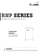
A. For typical placement in a compressed air system,
see drawing.
B. Air compressor intake–Locate air compressor so
that contaminants potentially harmful to the
dryer (e.g. ammonia) are not drawn into the air
system.
C. Clearances
Free air flow - Allow at least 12 inches (305 mm) on
the front and each side of the cabinet and 6 inches
(152 mm) at the back of the cabinet for free air flow.
Service - To facilitate maintenance leave 24 inches
(610 mm) of clearance in front of dryer.
D. Standard units are designed to operate in ambients
from 45 to 110°F (7 to 43°C).
E. Installations in altitudes above 4500 feet (1370 meters)
– Dryer is adjusted to operate in altitudes up to 4500
feet (1370 meters). If dryer is installed in an altitude
above this, and has not been preset at the factory for
this altitude, contact manufacturer’s Service Depart-
ment.
NOTE: Outdoor installation–Standard units are designed
for indoor installation. Contact manufacturer if installing
outdoors.
1.2 Mounting
Mount on floor or shelf free from vibration.
Aftercooler
Separator
Dryer
Oil Removal
Filter
Compressor
Power Cord
Air Inlet
Air Outlet
Quick Release
Locks
Air Flow
* Screws used for shipping only.
Remove after installation.
Separator
Temperature
Indicator
Power On
Light
On/Off Switch
Drain
Condenser

4
E
N
G
L
I
S
H
1.4 Electrical connections
A. Dryer is designed to operate on the voltage, phase,
and frequency listed on the serial number tag.
B. Dryer is supplied with a cord and plug. Install in a
receptacle of proper voltage.
NOTE:
Refrigeration condensing unit is designed to run continu-
ously and should NOT be wired to cycle on/off with the air
compressor.
NOTE:
Models 150 (115V only)—install plug in receptacle rated
for 20 amps.
1.3 Piping connections
A. Air Inlet—Connect compressed air line from air
source to air inlet.
WARNING: Refer to Serial Number Tag for maximum
working pressure. Do not exceed dryer’s Maximum
Working Pressure.
NOTE:
Install dryer in air system at highest pressure possible
(e.g. before pressure reducing valves).
NOTE:
Install dryer at coolest compressed air temperature
possible. Maximum inlet compressed air temperature:
120°F (49°C). If inlet air exceeds this temperature, precool
the air with an aftercooler.
B. Air Outlet—Connect air outlet to downstream
air lines.
C. By-pass piping—
If servicing the dryer without interrupting the
air supply is desired, piping should include
inlet and outlet valves and an air by-pass valve.
D. Water cooled models—cooling water inlet and
outlet
1. Connect cooling water supply to cooling water
inlet.
2. Connect cooling water return line to cooling
water outlet connection.
NOTE:
Strainer and water regulating valve are supplied on water
cooled models.
Air Inlet
Air Outlet
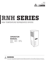
1.5 Moisture separator
A. Separator has an internal drain which automatically
discharges collected condensate. It may be desirable
to pipe the condensate from the Automatic Drain
outlet to a suitable drain.
NOTE:
Discharge is at system pressure. Drain line should be
anchored.
NOTE:
Condensate may contain oil. Comply with applicable laws
concerning proper disposal.
B. Separator has a knurled fitting with flexible drain
tubing attached. Be sure knurled fitting is tightened
by turning it counter-clockwise before operating
dryer.
TO CLOSE
TURN COUNTERCLOCKWISE

5
E
N
G
L
I
S
H
2.0 Operation
2.1 Minimum/Maximum operating conditions
A. Maximum inlet air pressure: refer to dryer serial
number tag
B. Minimum inlet air pressure: 30 psig (2.1 kgf/cm
2
)
C. Maximum inlet air temperature: 120°F (49°C)
D. Maximum ambient temperature:
Air-cooled models: 110°F (43°C)
Water-cooled models: 130°F (54°C)
E. Minimum ambient temperature: 45°F (7°C)
On/Off Switch Power-On Light Dewpoint Indicator (Green)
2.2 Start-up
Energize compressor by positioning the on/off switch in
the on (I) position. Compressor on light will illuminate.
2.3 Operating check points
Check the following on a periodic basis:
A. Green power on light is illuminated.
B. Dewpoint indicator is in green area.
C. Condensate is discharging from drain.

6
E
N
G
L
I
S
H
OUTLET DEWPOINT
DEW POINT
TEMPERATURE MULTIPLIER
°F °C
38 3 1.0
40 4 1.1
45 7 1.2
50 10 1.3
COOLING MEDIUM*
AMBIENT
TEMPERATURE MULTIPLIER
°F °C
80 27 1.12
90 32 1.06
100 38 1.00
110 43 0.94
INLET COMPRESSED AIR CONDITIONS
INLET INLET TEMPERATURES
PRESSURES 80
°F90°F 100°F 110°F 120°F
psig kgf/cm
2
27°C32°C38°C 43°C49°C
50 3.5 1.35 1.05 0.84 0.69 0.56
80 5.6 1.50 1.17 0.95 0.79 0.66
100 7.0 1.55 1.23 1.00 0.82 0.70
125 8.8 1.63 1.31 1.07 0.91 0.74
150 10.5 1.70 1.37 1.13 0.95 0.80
175 12.3 1.75 1.42 1.18 0.99 0.84
200 14.0 1.80 1.47 1.22 1.03 0.89
3.1 Condenser coil—
Clean off accumulated dust and dirt monthly.
3.2 Moisture separator—
Replace filter element when pressure drop across
dryer is excessive or annually.
3.3 Check separator daily to be sure automatic drain is
discharging.
3.4 Replace drain mechanism annually.
To facilitate service, maintenance kits are available.
3.0 Maintenance Sizing
Determining dryer capacity at actual operating
conditions
To determine the maximum inlet flow capacity of a dryer
at various operating conditions, multiply the rated
capacity from Table 1 by the multipliers shown in Table 2.
Example: How many scfm can an air-cooled model 125
handle when compressed air to be dried is at 80 psig and
90°F; ambient air temperature is 80°F; and a 35°F dew
point temperature is desired?
Answer: 125 x 1.17 x 1.12 x 1.0 = 163.8 scfm.
TABLE 2
Air capacity correction factors (Multipliers)
25 35 50 75 100 125 150
MODEL
Rated capacity of 60 Hz 25 35 50 75 100 125 150
air-cooled models (scfm) 50 Hz 21 29 42 63 84 105 125
TABLE 1
Rated capacity (scfm) and pressure drop @ 100 psig inlet
pressure, 100°F inlet temperature, and 100°F ambient
temperature
*Air-cooled models; water-cooled models use 1.15 multiplier if cooling water is
below 35°C, 95°F.
Element o-ring
Separator Element
Bowl o-ring
Drain Mechanis
m
Wave Spring
Tube
Hose
Barb

7
E
N
G
L
I
S
H
Minimum – Maximum Operating Conditions 25 35 50 75 100 / 125 150
Min.-Max. Inlet Air Pressure (compressed air at inlet to dryer) 30 psig (2.1 kgf/cm
2
) - 250 psig (17.6 kgf/cm
2
)
Max. Inlet Air Temp. (compressed air at inlet to dryer) 120°F (49°C)
Min.-Max. Ambient Temperature Air-cooled 45°F (7°C) - 110°F (43°C) Water-cooled 45°F (7°C) - 130°F (54°C)
Refrigeration System Data
Compressor Type Hermetic - Resistance Start, Induction Run - Non-Cycling
Refrigeration Compressor Horsepower 1/6 1/5 1/4 1/3 1/2 3/4
BTU/HR – Refrigeration Only
@ 35°F Evaporator & 100°F Ambient 60 Hz / 50 Hz 1010 / 842 1380 / 1150 2160 / 1800 2780 / 2317 4430 / 3692 6020 / 5017
Refrigerant Type R-134a R-134a R-134a R-134a R-134a R-134a
Refrigerant Charge See dryer serial number tag
Suction Pressure Setting (controlled by hot gas by-pass valve) 31.5 psig 31.5 psig 31.5 psig 31.5 psig 31.5 psig 31.5 psig
Condenser Fan Switch Setting (in-out) (psig) NA NA NA NA NA 110-70
Air Flow Across Condenser (cfm) 60 Hz / 50 Hz 105 / 98 235 / 196 275 / 229 220 / 183 350 / 292 530 / 440
Condenser Cooling Water Requirements (gpm @ 85°F)
NA NA NA NA NA 2.2 / 1.8
(water-cooled models only) (40 psig min. pressure)
Electrical
Nominal Voltages 115/1/60
Max.- Min. Voltage 127-104 127-104 127-104 127-104 127-104 127-104
Rated Load Amps 3.4 3.9 5.9 7.4 10.3 14.7
Locked Rotor Amps 18.0 22.0 28.0 35.0 48.0 66.3
Minimum Circuit Ampacity 4.0 4.7 7.3 9.1 12.4 18.3
Branch Circuit Fuse Size (amps) 15 15 15 15 20 25
Watts @ 35°F Evaporator & 100°F Ambient 280 290 465 600 815 1060
Resistance (ohms) Single phase Start C/S --- --- --- --- --- 3.15
Run C/R --- --- --- --- --- 0.416
Overload Thermal & Current (Auto reset)
Nominal Voltages 208-230/1/60
Max.-Min. Voltage 253-187 253-187 253-187 253-198 253-187 253-198
Rated Load Amps 1.8 2.1 3.0 4.1 5.1 8.3
Locked Rotor Amps 8.5 13.7 14.4 19.0 23.0 33.5
Minimum Circuit Ampacity 2.2 2.6 3.7 5.1 5.2 10.5
Branch Circuit Fuse Size (amps) 15 15 15 15 15 15
Watts @ 35°F Evaporator & 100°F Ambient 280 290 470 600 815 1060
Resistance (ohms) Single phase Start C/S --- --- --- --- --- 7.92
Run C/R --- --- --- --- --- 1.55
Overload Thermal & Current (Auto reset)
Nominal Voltages 220-240/1/50
Max.-Min. Voltage 264-198 264-198 264-198 264-198 264-198 264-198
Rated Load Amps 1.6 1.8 2.6 3.5 4.2 7.6
Locked Rotor Amps 8.7 10.7 14.5 15.2 21.0 53.0
Minimum Circuit Ampacity 2.0 2.2 3.2 4.4 5.2 9.9
Branch Circuit Fuse Size (amps) 15 15 15 15 15 15
Watts @ 35°F Evaporator & 100°F Ambient 223 257 395 507 669 930
Resistance (ohms) Single phase Start C/S --- --- --- --- --- 10.49
Run C/R --- --- --- --- --- 1.8
Overload Thermal & Current (Auto reset)
ENGINEERING DATA

8
E
N
G
L
I
S
H
ELECTRICAL SCHEMATIC
Models 25, 35 - 115V/60 Hz; 208-230V/60Hz; 220-240V/50 Hz
Model 50 - 115V/60 Hz; 220-240V/50 Hz
Model 75 - 115V/60 Hz
Model 50 - 208-230V/60Hz
Model 75 - 208-230V/60 Hz; 220-240V/50 Hz
Models 100, 125 - All Voltages
Model 150 - 230V/60 Hz
Legend
PBS - Push button switch
1LT - Power-on light
SR - Start Relay
CAP - Start Capacitor
MTR - Compressor
FM - Fan Motor
OL - Overload
FPS - Fan Pressure Switch (Only on 150 scfm)
CT - Contactor w/115v coil
SW - On/Off Switch
Model 150 - 115V/60 Hz

9
E
N
G
L
I
S
H
DIMENSIONS/WEIGHTS
Dimensions
inches
Model 25 35 50 75 100 125 150
A 17 17 19-15/16 21-9/16 21-9/16 26-15/16 26-15/16
B 22 22 24-7/16 28-11/16 28-11/16 30-1/8 30-1/8
C 17 17 17 20 20 23-3/4 23-3/4
D 1-13/16 1-13/16 1-15/16 1-15/16 1-15/16 2-3/16 2-3/16
E 44 55555
F 15/16 15/16 15/16 15/16 15/16 15/16 15/16
G 1-7/8 1-7/8 1-7/8 1-7/8 1-7/8 1-7/8 1-7/8
H 33 33333
I 1-3/16 1-3/16 1-3/16 1-3/16 1-3/16 1-3/16 1-3/16
Inlet/Outlet
Connections 3/4 3/4 1 1 1 1-1/2 1-1/2
Weights
lbs 105 118 156 180 198 229 230
D
E
F
A
H
G
I
C
G
H
B
Left Side View
Front View Right Side View
Electrical Entry Drain Outlet

10
E
N
G
L
I
S
H
TROUBLESHOOTING GUIDE
SYMPTOM
A. Water downstream of dryer
B. High pressure drop across
dryer
C. Dew point indicator in red
area
D. Refrigeration system not
functioning properly
1. Power on light off
2. Refrigerant compressor
cycles on and off
POSSIBLE CAUSE(S)
1. Residual free moisture remaining
in downstream pipelines
2. Air by-pass system is open
3. Inlet and Outlet connections are
reversed
4. Temperatures surrounding air
lines downstream of dryer have
dropped below dryers dew point
rating
5. Excessive free moisture (bulk
liquid) at dryer inlet
6. Condensate not being automati-
cally drained
Drain mechanism is clogged or
inoperative.
Drain line is restricted or frozen.
Electric drains–timer not set to
allow for sufficient condensate
removal
7. Dryer overloaded resulting in
elevated dew point.
8. Refrigeration system not func-
tioning properly resulting in
elevated dew point.
1. Excessive air flow
2. Freezing of moisture in evapora-
tor because of refrigeration
system improperly functioning.
3. Separator filter element clogged.
1. Dryer overloaded resulting in high
air outlet temperature.
2. Refrigeration system not func-
tioning properly resulting in high
air outlet temperature.
a. Power failure
b. Line disconnect switch open
c. Blown fuses, open breaker
d. Faulty wiring, loose terminals
a. High or low ambient conditions
b. Air-cooled models–Dirty, clogged
condenser fins, obstructed air
flow across condenser, or non
functioning fan motor or fan
control switch.
c. Water-cooled models–Cooling
water temperature too high, or
flow too low, faulty water regulat-
ing valve, clogged water strainer.
CORRECTIVE ACTION
Blow out system with dry air
Check valve positions
Check for correct connection
Insulate or heat trace air lines exposed to
low ambients or dry air to lower dew point
Install separator ahead of dryer
Replace drain mechanism if inoperative
Open drain line
Electric drains–reset time so that all liquid
is discharged
Check inlet air temperature and pressure,
flow rate (compressor capacity) and
ambient air or water temperature.
See D below
Check flow rate
See D below
Replace filter element.
See A 7
See D below
Check power to unit
Close disconnect switch
Check for continuity
Have electrician check electrical
connections
Check min./max. temperature ranges
Clean condenser and check for free air
flow, if problem persists contact qualified
refrigeration repairman or manufacturer’s
service department.
Clean strainer, check water flow and
temperature, if problem persists contact
qualified refrigeration repairman or
manufacturer’s service department.

11
E
N
G
L
I
S
H
75 100 & 125 150
PARTS
115/1/60 208-230/1/60 220-240/1/50 115/1/60 208-230/1/60 220-240/1/50 115/1/60 208-230/1/60 220-240/1/50
DESCRIPTION 100/1/50 100/1/50 100/1/50
Condensing Unit (air-cooled) 4130.122.12 4130.122.13 4130.122.14 4130.123.12 4130.123.13 4130.123.14 4130.134.31 4130.134.32 4130.134.33
Compressor Only 4130.108.44 4130.108.45 4130.108.46 4130.108.47 4130.108.48 4130.108.49 4130.108.50 4130.108.51 4130.108.52
Overload 5925.578.7 5925.578.8 5925.578.9 5925.578.10 5925.578.11 5925.578.12 5925.578.13 5925.578.14 5925.578.15
Start Relay 5945.683.7 5945.683.8 5945.683.9 5945.683.10 5945.683.11 5945.683.12 5945.683.13 5945.683.14 5945.683.15
Start Capacitor — 5910.103.26 5910.103.27 5910.103.28 5910.103.29 5910.103.29 5910.103.37 5910.103.38 5910.103.39
Fan Motor 6105.238.31 6105.238.32 6105.238.32 6105.238.33 6105.238.34 6105.238.34 6105.238.35 6105.238.36 6105.238.36
Fan Blade 4140.227.19 4140.227.25 4140.227.25 4140.227.20 4140.227.20 4140.227.20 4140.227.21 4140.227.21 4140.227.21
Condenser (air-cooled) 4130.111.20 4130.111.20 4130.111.20 4130.111.21 4130.111.21 4130.111.21 4130.111.22 4130.111.22 4130.111.22
Dryer 4130.165.14 4130.165.14 4130.165.14 4130.165.14 4130.165.14 4130.165.14 4130.165.14 4130.165.14 4130.165.14
Fan Pressure Switch — — — — — — 4130.138.13 4130.138.13 4130.138.13
Hot gas by-pass valve 9802-1 9802-1 9802-1 9802-1 9802-1 9802-1 9802-1 9802-1 9802-1
By-pass valve strainer 4130.701.8 4130.701.8 4130.701.8 4130.701.8 4130.701.8 4130.701.8 4130.701.8 4130.701.8 4130.701.8
Light assy., green 6350.457.25 6350.457.23 6350.457.23 6350.457.25 6350.457.23 6350.457.23 6350.457.25 6350.457.23 6350.457.23
Dew Point Indicator 6685.283.1 6685.283.1 6685.283.1 6685.283.1 6685.283.1 6685.283.1 6685.283.1 6685.283.1 6685.283.1
On/off switch 6110.706.13 6110.706.13 6110.706.13 6110.706.13 6110.706.13 6110.706.13 6110.706.13 6110.706.13 6110.706.13
Condenser (water-cooled) — — — — — — 4130.134.34 4130.134.35 4130.134.36
Water Control Valve — — — — — — 4130.145.22 4130.145.22 4130.145.22
Water Strainer — — — — — — 4731.735.1 4731.735.1 4731.735.1
Screen, water strainer — — — — — — 4731.735.5 4731.735.5 4731.735.5
Contactor — — — — — — 5910.134.11 — —
Maintenance Kit HPRMK4 HPRMK4 HPRMK4 * * * HPRMK5 HPRMK5 HPRMK5
Element E9-24 E9-24 E9-24 ** ** ** E9-28 E9-28 E9-28
Drain 4460.151.10 4460.151.10 4460.151.10 4460.151.10 4460.151.10 4460.151.10 4460.151.10 4460.151.10 4460.151.10
25 35 50
PARTS
115/1/60 208-230/1/60 220-240/1/50 115/1/60 208-230/1/60 220-240/1/50 115/1/60 208-230/1/60 220-240/1/50
DESCRIPTION 100/1/50
100/1/50 100/1/50
Condensing Unit (air-cooled) 4130.120.7 4130.120.8 4130.120.9 4130.121.8 4130.121.9 4130.121.10 4130.122.10 4130.122.11 4130.122.15
Compressor Only 4130.108.34 4130.108.61 4130.108.35 4130.108.38 4130.108.39 4130.108.40 4130.108.41 4130.108.42 4130.108.43
Overload 5925.570.2 5925.578.24 5925.570.3 5925.578.1 5925.578.2 5925.578.3 5925.578.4 5925.578.5 5925.578.6
Start Relay 5945.655.5 5945.683.24 5945.655.6 5945.683.1 5945.683.2 5945.683.3 5945.683.4 5945.683.5 5945.683.6
Start Capacitor — — — — — — — 5910.103.23 —
Fan Motor 6105.239.1 6105.237.4 6105.237.4 6105.238.27 6105.238.28 6105.238.28 6105.238.29 6105.238.30 6105.238.30
Fan Blade 4140.228.2 4140.228.2 4140.228.2 4140.227.17 4140.227.17 4140.227.17 4140.227.18 4140.227.18 4140.227.18
Condenser (air-cooled) 4130.110.26 4130.110.26 4130.110.26 4130.111.18 4130.111.18 4130.111.18 4130.111.19 4130.111.19 4130.111.19
Dryer 4130.165.14 4130.165.14 4130.165.14 4130.165.14 4130.165.14 4130.165.14 4130.165.14 4130.165.14 4130.165.14
Hot gas by-pass valve 9802-1 9802-1 9802-1 9802-1 9802-1 9802-1 9802-1 9802-1 9802-1
By-pass valve strainer 4130.701.8 4130.701.8 4130.701.8 4130.701.8 4130.701.8 4130.701.8 4130.701.8 4130.701.8 4130.701.8
Light assy., green 6350.457.25 6350.457.23 6350.457.23 6350.457.25 6350.457.23 6350.457.23 6350.457.25 6350.457.23 6350.457.23
Dew Point Indicator 6685.283.1 6685.283.1 6685.283.1 6685.283.1 6685.283.1 6685.283.1 6685.283.1 6685.283.1 6685.283.1
On/off switch 6110.706.13 6110.706.13 6110.706.13 6110.706.13 6110.706.13 6110.706.13 6110.706.13 6110.706.13 6110.706.13
Maintenance Kit HPRMK2 HPRMK2 HPRMK2 HPRMK2 HPRMK2 HPRMK2 HPRMK3 HPRMK3 HPRMK3
Element E9-16 E9-16 E9-16 E9-16 E9-16 E9-16 E9-20 E9-20 E9-20
Drain 4460.151.10 4460.151.10 4460.151.10 4460.151.10 4460.151.10 4460.151.10 4460.151.10 4460.151.10 4460.151.10
PARTS LIST
* Model 100 - HPRMK4
Model 125 - HPRMK5
** Model 100 - E9-24
Model 125 - E9-28

12
E
N
G
L
I
S
H
WARRANTY
The manufacturer warrants the product manufactured by it, when properly installed, operated, applied, and maintained
in accordance with procedures and recommendations outlined in manufacturer’s instruction manuals, to be free from
defects in material or workmanship for a period as specified below, provided such defect is discovered and brought to
the manufacturer’s attention within the aforesaid warranty period.
The manufacturer will repair or replace any product or part determined to be defective by the manufacturer within the
warranty period, provided such defect occurred in normal service and not as a result of misuse, abuse, neglect or
accident. Normal maintenance items requiring routine replacement are not warranted. The warranty covers parts and
labor for the warranty period unless otherwise specified. Repair or replacement shall be made at the factory or the
installation site, at the sole option of the manufacturer. Any service performed on the product by anyone other than
the manufacturer must first be authorized by the manufacturer.
Unauthorized service voids the warranty and any resulting charge or subsequent claim will not be paid. Products
repaired or replaced under warranty shall be warranted for the unexpired portion of the warranty applying to the
original product.
The foregoing is the exclusive remedy of any buyer of the manufacturer’s product. The maximum damages liability of
the manufacturer is the original purchase price of the product or part.
THE FOREGOING WARRANTY IS EXCLUSIVE AND IN LIEU OF ALL OTHER WARRANTIES, WHETHER WRITTEN, ORAL, OR STATU-
TORY, AND IS EXPRESSLY IN LIEU OF THE IMPLIED WARRANTY OF MERCHANTABILITY AND THE IMPLIED WARRANTY OF
FITNESS FOR A PARTICULAR PURPOSE. THE MANUFACTURER SHALL NOT BE LIABLE FOR LOSS OR DAMAGE BY REASON OF
STRICT LIABILITY IN TORT OR ITS NEGLIGENCE IN WHATEVER MANNER INCLUDING DESIGN, MANUFACTURE OR INSPECTION OF
THE EQUIPMENT OR ITS FAILURE TO DISCOVER, REPORT, REPAIR, OR MODIFY LATENT DEFECTS INHERENT THEREIN.
THE MANUFACTURER, HIS REPRESENTATIVE OR DISTRIBUTOR SHALL NOT BE LIABLE FOR LOSS OF USE OF THE PRODUCT OR
OTHER INCIDENTAL OR CONSEQUENTIAL COSTS, EXPENSES, OR DAMAGES INCURRED BY THE BUYER, WHETHER ARISING
FROM BREACH OF WARRANTY , NEGLIGENCE OR STRICT LIABILITY IN TORT.
The manufacturer does not warrant any product, part, material, component, or accessory manufactured by others and
sold or supplied in connection with the sale of manufacturer’s products.
Warranty Period
Parts and labor for two (2) years from the date of shipment from the factory; heat exchangers are covered (parts
only) for an additional three (3) years (total of five [5]). On units that manufacturer requests be returned to the
factory, a one time removal/reinstallation labor allowance as noted in the Service Warranty Policies and Procedures
Handbook will apply. Freight to the factory from the installation site and to the installation site from the factory will
be paid by the manufacturer; means of transportation to be specified by manufacturer.
AUTHORIZATION FROM THE SERVICE DEPARTMENT IS NECESSARY BEFORE MATERIAL IS
RETURNED TO THE FACTORY OR IN-WARRANTY REPAIRS ARE MADE.
Division of Hansen Inc.
Canonsburg, PA 15317-1700 U.S.A.
Tel 724-745-1555 Fax 724-745-6040
SERVICE DEPARTMENT: (724) 746-1100

E
S
P
A
Ñ
O
L
1 Sp
7610.483.7B 5/02
Manuel de Instrucciones
Modelos: HPRP 25, 35, 50, 75,
100, 125, 150
Contenido
INFORMACION GENERAL DE SEGURIDAD ................. 2
RECEPCION, TRANSPORTE Y DESEMPACADO .......... 2
1.0 INSTALACION ...................................................... 3
2.0 OPERACION ........................................................ 5
3.0 MANTENIMIENTO ............................................... 6
DIMENSIONAMIENTO ................................................ 6
ELECTRICAL SCHEMATICS ......................................... 7
INFORMACION DE INGENIERIA ................................. 8
DIMENSIONES/PESOS ............................................... 9
GUIA EN CASO DE FALLAS ...................................... 10
LISTA DE PARTES .................................................... 11
GARANTIA ............................................................... 12
SECADORES
DE AIRE
COMPRIMIDO TIPO
REFRIGERATIVO
DEPARTAMENTO DE SERVICIO (724) 746-1100

E
S
P
A
Ñ
O
L
2 Sp
1. DISPOSITIVOS PRESURIZADOS:
Este equipo es un dispositivo sujeto a
presión. No exceda la presión máxima
de operación que se muestra en la
placa del secador.
Asegúrese que el equipo esté despresurizado antes de
realizar cualquier mantenimiento o desarmarlo para
servicio.
2. SISTEMA ELECTRICO:
Este equipo requiere energía eléctrica
para operar. Instálelo de acuerdo a las
regulaciones vigentes.
El equipo estándar no incluye protección eléctrica para
ser instalado en ambientes peligrosos.
Desconecte la energía eléctrica del equipo cuando se
realice cualquier servicio.
3. AIRE RESPIRABLE:
El aire tratado por este equipo puede no
ser respirable sin purificación adicional.
Refiérase a los estándares aplicables y a
las especificaciones de los requerimientos para aire
respirable.
INFORMACION GENERAL DE SEGURIDAD RECEPCION, TRANSPORTE Y DESEMPACADO
A. RECEPCION
Este embarque ha sido ampliamente verificado,
inspeccionado y empacado antes de abandonar nuestra
planta.
El transportista lo recibió en buenas condiciones según
lo manifiesta.
Verifique cualquier Faltante o Daño Visible.
Si el embarque muestra evidencia de mercancía faltante
o daño al momento de ser entregado, insista que se
anote en el recibo del transportista que la mercancía
llegó incompleta ó dañada.
B. DESEMPACADO
Verifique que no exista ningún Faltante o algún Daño
Oculto.
Cuando el equipo se ha entregado aparentemente en
buenas condiciones, pero al momento de
desempacarlo se nota cualquier daño, notifique a la
compañía transportista inmediatamente e insista que
su agente inspeccione la mercancía.
Cualquier reclamación por algún daño oculto a la
mercancía no es de nuestra responsabilidad, ya que las
condiciones de venta especifican L.A.B. punto de
embarque.
C. TRANSPORTE
Al mover o transportar el secador, no lo incline.
D. ALMACENAMIENTO
IMPORTANTE - No almacene el secador en temperaturas
mayores de 54.4
o
C, 130
o
F.

E
S
P
A
Ñ
O
L
3 Sp
IMPORTANTE: LEASE EL MANUAL DE INSTRUCCIONES
COMPLETAMENTE ANTES DE ARRANCAR EL EQUIPO
1.0 Instalacion
1.1 Localización
A. Observe el dibujo para la ubicación más frecuente
dentro de los sistemas de aire comprimido.
B. Entrada del compresor de aire - Localice el
compresor de tal forma que no entre al sistema
neumático ningún contaminante potencialmente
peligroso al secador (p. ej. Amoniaco).
C. Espacios Libres
Flujo libre de aire - Se debe respetar una distancia
de 305 mm (12 pulgadas) en el frente y a cada lado
del gabinete y 152 mm (6 pulgadas) en la parte
posterior del gabinete para que el aire fluya
libremente.
Servicio – Para facilitar el mantenimiento, respete
una distancia de 610 mm (24 pulgadas) en el frente
del secador.
D. Las unidades estándar están diseñadas para trabajar
a una temperatura ambiente de 7 a 43
o
C, 45 a
110
o
F.
E. Instalaciones en alturas mayores de 1370 metros
(4500 pies) sobre el nivel del mar - El secador está
calibrado para operar a altitudes no mayores de
1370 metros (4500 pies) sobre el nivel del mar. Si el
secador está instalado a una altura mayor, y no ha
sido calibrado en fábrica para operar bajo estas
condiciones, póngase en contacto con el
Departamento de Servicio del Fabricante.
NOTA:
Instalación en exteriores - Las unidades estándar están
diseñadas para trabajar en interiores. Póngase en
contacto con el fabricante si el equipo será instalado al
aire libre.
1.2 Montaje
Instálese en el piso o en un gabinete libre de vibraciones.
Postenfriador
Separador
Secador
Filtro de
Remoción de
Aceite
Compresor
Cable de
Conexión
Salida de
Aire
Seguros de
Apertura
Rápida
Flujo
de Aire
* Tornillos Utilizados Durante
el Embarque Unicamente
Separador
Luz de Unidad
Energizada
Interruptor de
Encendido/
Apagado
Dren
Condensador
Entrada de
Aire
Indicador de
Temperatura

E
S
P
A
Ñ
O
L
4 Sp
1.4 Conexión eléctrica
A. La unidad está diseñada para operar con el voltaje,
fases y frecuencia indicados en la placa del secador.
B. El secador se surte con cable y enchufe. Conéctese en
un contacto para el voltaje adecuado.
NOTA:
La unidad de refrigeración está diseñada para operar
continuamente y NO se debe conectar para que encienda
y apague junto con el compresor.
NOTA:
Modelo 150 (115 V únicamente) - Instale un contacto para
20 Amps.
1.3 Conexión a la tubería
A. Entrada de aire - Conecte la línea de aire comprimido
que viene del compresor de aire a la entrada del
secador.
PRECAUCION
Refiérase a la placa del secador para determinar la presión
máxima de operación del equipo. No exceda la presión
máxima de operación del secador.
NOTA:
Instale el secador en el punto del sistema donde se pueda
obtener la máxima presión posible (p. ej. antes de
cualquier regulador de presión).
NOTA:
Instale el secador en el punto donde se pueda obtener la
temperatura más baja en el aire comprimido. La
temperatura máxima de operación del equipo es de 49
o
C
(120
o
F). Si el aire de entrada sobrepasa ésta temperatura,
es necesario enfriarlo con un postenfriador.
B. Salida de aire - Conecte la salida del secador a la línea
principal de suministro de aire al sistema.
C. Tubería de derivación - Si es necesario realizar
cualquier servicio al secador sin interrumpir el flujo de
aire, la tubería debe incluir una válvula de paso a la
entrada y a la salida del secador, así como una válvula
de derivación.
D. Modelos enfriados por agua - Conexiones de entrada y
salida de agua de enfriamiento
1. Conecte la línea de abastecimiento de agua de
enfriamiento a la conexión de entrada de agua
del secador.
2. Conecte la salida de agua de enfriamiento del
secador a la conexión de retorno de agua.
NOTA:
Los modelos enfriados por agua se surten con regulador
de flujo de agua y cedazo.
Entrada de
Aire
Salida de
Aire
1.5 Separador de humedad
A. El separador cuenta con un dren interno que descarga
automáticamente los condensados. Se puede
conectar con tubería para drenar los condensados al
lugar apropiado.
NOTA:
La descarga se efectúa a la presión del sistema. Es
necesario anclar la tubería de drenaje.
NOTA:
Los condensados pueden tener aceite. Asegúrese de
cumplir con las leyes aplicables de desechos industriales.
B. El separador tiene una válvula estriada y un tubo de
plástico. Asegúrese que la válvula esté completamente
cerrada girándola en sentido de las manecillas del reloj
antes de arrancar el secador.
OC O
PARA CERRAR
GIRE EN SENTIDO DE LAS MANECILLAS
DEL RELOJ

E
S
P
A
Ñ
O
L
5 Sp
2.0 Operacion
2.1 Condiciones mínimas/máximas de operación
A. Presión máxima del aire de entrada: Refiérase a la
placa del equipo
B. Presión mínima del aire de entrada: 2.1 Kgf/cm
2
(30 psig)
C. Temperatura máxima del aire de entrada: 49
o
C (120
o
F)
D. Temperatura ambiente máxima de operación:
Modelos enfriados por aire: 43
o
C (110
o
F)
Modelos enfriados por agua: 54
o
C (130
o
F)
E. Temperatura ambiente mínima de operación: 7
o
C
(45
o
F)
Interruptor de
Encendido/
Apagado
Luz de
Compresor
Energizado
Indicador de Punto de
Rocío (Verde)
2.2 Arranque Inicial
Energice el compresor presionando en botón marcado ‘I’. Se
debe encender la luz compresor encendido.
2.3 Puntos de Verificación de Operaciónj.
Verifique periódicamente lo siguiente:
A. La luz de encendido verde debe estar encendida.
B. El indicador de punto de rocío debe estar en el área
verde.
C. Los condensados deben descargarse periódicamente del
dren.

E
S
P
A
Ñ
O
L
6 Sp
PUNTO DE ROCIO A LA SALIDA
TEMPERATURA DEL
PUNTO DE ROCIO FACTOR
°F °C
38 3 1.0
40 4 1.1
45 7 1.2
50 10 1.3
TEDIO DE ENFRIAMIENTO*
TEMPERATURA
AMBIENTE FACTOR
°F °C
80 27 1.12
90 32 1.06
100 38 1.00
110 43 0.94
CONDICIONES DEL AIRE COMPRIMIDO A LA ENTRADA
ENTRADA TEMPERATURAS DE ENTRADA
PRESION DE 80
°F90°F 100°F 110°F 120°F
psig kgf/cm
2
27°C32°C38°C 43°C49°C
50 3.5 1.35 1.05 0.84 0.69 0.56
80 5.6 1.50 1.17 0.95 0.79 0.66
100 7.0 1.55 1.23 1.00 0.82 0.70
125 8.8 1.63 1.31 1.07 0.91 0.74
150 10.5 1.70 1.37 1.13 0.95 0.80
175 12.3 1.75 1.42 1.18 0.99 0.84
200 14.0 1.80 1.47 1.22 1.03 0.89
3.0 Mantenimiento
3.1 Radiador del Condensador –
Limpiese mensualmente el polvo y suciedad
acumulados.
3.2 Separador de Condensados -
Reemplace el elemento del separador cuando la
caída de presión a través del secador sea excesiva, o
cuando menos una vez al año.
3.3 Verifique diariamente que los drenes automáticos
estén descargando condensados.
3.4 Reemplace el mecanismo del dren una vez al año.
Para facilitar el servicio, existen disponibles kits de
mantenimiento.
Dimensionamiento
Determinación de la capacidad del secador bajo las
condiciones actuales de operación
Para determinar el flujo máximo a la entrada del secador
bajo diferentes condiciones de operación, multiplique la
capacidad nominal de la Tabla 1 por el factor mostrado en
la Tabla 2.
Ejemplo: Determine la capacidad de un secador enfriado
por aire, de 125 scfm si el aire comprimido está a una
temperatura de 90
o
F y con una presión de 80 psig; la
temperatura ambiente es de 80
o
F y se requiere un punto
de rocío de 35
o
F.
Respuesta: 125 x 1.17 x 1.12 x 1.0 = 163.8 scfm.
TABLA 2
Factores de Corrección de la capacidad de flujo de aire
25 35 50 75 100 125 150
MODELO
Capacidad Nominal, Modelos 60 Hz 25 35 50 75 100 125 150
enfriados por aire Nm
3
/min(scfm) 50 Hz 21 29 42 63 84 105 125
TABLA 1
Capacidad Nominal y Caída de Presión @ presión de entrada
de 7 Kg/cm
2
(100 psig), temperatura de entrada de 38
o
C
(100
o
F) y temperatura ambiente de 38
o
C (100
o
F)
*Modelos enfriados por aire; modelos enfriados por agua, utilice un factor de 1.15
si el agua de enfriamiento se encuentra a menos de 35
o
C, 95
o
F.
NOTA:
Modelo 125 - Baje el collar y el vaso tanto como sea
posible. Destornille el cartucho del filtro/separador y
deposítelo dentro del vaso. Remueva el vaso, collar y
cartucho.
Sello 'O' del Elemento
Elemento Separador
Sello ' O' del Vaso
Mecanismo del Dren
Resorte
Manguera
Conector de
la Manguera

E
S
P
A
Ñ
O
L
7 Sp
Condiciones de Operación Mínimas y Máximas 25 35 50 75 100 / 125 150
Presión Mínima/Máxima de Entrada
(del aire comprimido a la Entrada del secador) 30 psig (2.1 kgf/cm
2
) - 250 psig (17.6 kgf/cm
2
)
Temperatura Máxima de Entrada
(del aire comprimido a la entrada del secador) 120°F (49°C)
Temperatura Mínima-Máxima del Ambiente Enfriados por Aire 7 - 43
o
C, 45 - 110
o
F; Enfriados por Agua 7 - 54
o
C, 45 - 130
o
F
Información Técnica del Sistema de Refrigeración
Tipo de Compresor Hermético - Arranque por Resistencia, Operación por Inducción - No Cíclico
Potencia del Compresor de Refrigeración 1/6 1/5 1/4 1/3 1/2 3/4
BTU/HR Exclusivamente del Sistema
de Refrigeración @ 35
o
F Evaporador y 100
o
F Ambiente 60 Hz / 50 Hz 1010 / 842 1380 / 1150 2160 / 1800 2780 / 2317 4430 / 3692 6020 / 5017
Tipo de Refrigerante R-134a R-134a R-134a R-134a R-134a R-134a
Carga de Refrigerante Refiérase a la placa del equipo
Ajuste de Presión de Succión (controlada por la válvula
de derivación de gas caliente) 31.5 psig 31.5 psig 31.5 psig 31.5 psig 31.5 psig 31.5 psig
Ajuste del Interruptor de los Ventiladores (entra-sale) (psig) NA NA NA NA NA 110-70
Flujo de Aire a Través del Condensador (cfm) 60 Hz / 50 Hz 105 / 98 235 / 196 275 / 229 220 / 183 350 / 292 530 / 440
Requieriemiento de Agua de Enfriamiento en el Condensador Lts. @ 30°C
NA NA NA NA NA 2.2 / 1.8
(gpm @ 85°F) (modelos enfriados por agua únicamente)
(presión mínima 40 psig)
Información Eléctrica
Voltaje Nominal 115/1/60
Voltaje Min. - Max. 127-104 127-104 127-104 127-104 127-104 127-104
Consumo de Energía Amperes Unidad a Plena Carga 3.4 3.9 5.9 7.4 10.3 14.7
Consumo de Energía Amperes Rotor Bloqueado 18.0 22.0 28.0 35.0 48.0 66.3
Capacidad Mínima del Circuito 4.0 4.7 7.3 9.1 12.4 18.3
Tamaño del Fusible del Circuito (amps) 15 15 15 15 20 25
Watts @ 1.5
o
C, 35
o
F Evaporador y 38
o
C, 100
o
F Ambiente 280 290 465 600 815 1060
Resistencia (ohms) Una fase Arranque C/S --- --- --- --- --- 3.15
Operación C/R --- --- --- --- --- 0.416
Protección Térmica Térmica y de Corriente (Restablecimiento Automático)
Voltaje Nominal 208-230/1/60
Voltaje Min. - Max. 253-187 253-187 253-187 253-198 253-187 253-198
Consumo de Energía Amperes Unidad a Plena Carga 1.8 2.1 3.0 4.1 5.1 8.3
Consumo de Energía Amperes Rotor Bloqueado 8.5 13.7 14.4 19.0 23.0 33.5
Capacidad Mínima del Circuito 2.2 2.6 3.7 5.1 5.2 10.5
Tamaño del Fusible del Circuito (amps) 15 15 15 15 15 15
Watts @ 1.5
o
C, 35
o
F Evaporador y 38
o
C, 100
o
F Ambiente 280 290 470 600 815 1060
Resistencia (ohms) Una fase Arranque C/S --- --- --- --- --- 7.92
Operación C/R --- --- --- --- --- 1.55
Protección Térmica Térmica y de Corriente (Restablecimiento Automático)
Voltaje Nominal 220-240/1/50
Voltaje Min. - Max. 264-198 264-198 264-198 264-198 264-198 264-198
Consumo de Energía Amperes Unidad a Plena Carga 1.6 1.8 2.6 3.5 4.2 7.6
Consumo de Energía Amperes Rotor Bloqueado 8.7 10.7 14.5 15.2 21.0 53.0
Capacidad Mínima del Circuito 2.0 2.2 3.2 4.4 5.2 9.9
Tamaño del Fusible del Circuito (amps) 15 15 15 15 15 15
Watts @ 1.5
o
C, 35
o
F Evaporador y 38
o
C, 100
o
F Ambiente 223 257 395 507 669 930
Resistencia (ohms) Una fase Arranque C/S --- --- --- --- --- 10.49
Operación C/R --- --- --- --- --- 1.8
Protección Térmica Térmica y de Corriente (Restablecimiento Automático)
Informacion de Ingenieria

E
S
P
A
Ñ
O
L
8 Sp
Diagrama Electrico
Modelos 25, 35 - 115V/60 Hz; 208-230V/60Hz; 220-240V/50 Hz
Modelo 50 - 115V/60 Hz; 220-240V/50 Hz
Modelo 75 - 115V/60 Hz
Modelo 50 - 208-230V/60Hz
Modelo 75 - 208-230V/60 Hz; 220-240V/50 Hz
Modelos 100, 125 - Todos los voltajes
Modelo 150 - 230V/60Hz
Description
PBS - Interruptor Principal
1LT - Luz de Unidad Energizada
SR - Relevador de Arranque
MTR - Compresor
FM - Motor del Ventilador
OL - Protección Térmica
FPS - Interruptor de Presión del Ventilador
(unicamente en modelos de 150 scfm)
CT - Contactor y Bobina 115v
SW - Interruptor de Encendido/Apagado
Modelo 150 - 115V/60 Hz
/