Page is loading ...

1
Before You Start
Your AP-PS20 Light Kit is exclusively designed for your
Kubota Seeder Model No.
AP-PS2072 & AP-PS2086 . . . . . . . . . . . . . . . All S/N’s
Please read these installation instructions and your
Primary Seeder Operator’s Manual thoroughly before
beginning. Especially read information relating to safety
concerns. Included in the Operator’s Manual is important
information on operation, adjustment, troubleshooting,
and maintenance for this implement.
Purchase separate Operator’s and Parts Manuals from
your nearest Kubota dealer or download manuals free of
charge from our web site at www.landpride.com Have
model and serial numbers handy when placing an order.
Manual Part Numbers:
• Operator’s Manual . . . . . . . . . . . . . . . 313-992MK
• Parts Manual . . . . . . . . . . . . . . . . . . . . 313-992PK
Further Assistance
Your dealer wants you to be satisfied with your Primary
Seeder’s new accessory light kit. If for any reason you do
not understand any part of this manual or are not
satisfied with the service received, the following actions
are suggested:
1. Discuss any problems you have with your accessory
kit with your dealership service personnel so they
can address the problem.
1. If you are still not satisfied, seek out the owner or
general manager of the dealership, explain the
question/problem, and request assistance.
2. For further assistance write to:
Kubota by Land Pride
Service Department
1525 East North Street
P.O. Box 5060
Salina, Ks. 67402-5060
E-mail address
lpser[email protected]
When you see this symbol, the subsequent
instructions and warnings are serious - follow
without exception. Your life and the lives of others
depend on it.
!
IMPORTANT: Before you begin, read these
instructions and check to be sure all parts and tools
are accounted for. Please retain these installation
instructions for future reference and parts ordering
information.
General Information
These assembly instructions apply to the following
Seeder Light Kit Accessories listed below:
313-992A . . . . . . . . . . . . . . . . . . . . . Light Kit AP-PS20
Tools required:
•
Safety glasses
• Work gloves
• Pencil
• Tape Measure
• Side diagonal cutters
• Two 7/16” box end or open end wrenches
Power Machine Shutdown
The following are basic power machine shutdown
procedures. Follow these procedures and any additional
shutdown procedures provided in your power machine
Operator’s Manual before leaving the operator’s seat.
1. Reduce engine speed and shut-off all power to the
implement.
2. Park on solid, level ground and lower implement until
it is flat on the ground or on non-concrete support
blocks.
3. If shutting down a tractor, put tractor in park or set
park brake.
4. Turn off engine, and remove switch key to prevent
unauthorized starting.
5. Relieve all hydraulic pressures.
6. If included, raise seat bar and move controls until
both lock.
7. Wait for all components to come to a complete stop
before leaving the operator’s seat.
8. Use steps, grab-handles, and anti-slip surfaces
when stepping on and off the power machine.
Assembly Instructions
Turn to page 2 for detailed assembly instructions on how
to install your new accessory light kit on your Primary
Seeder.
Additionally, a detailed listing of parts for this accessory
kit is provided on page 4. Use the list as a checklist to
inventory parts received. Please contact your local
Kubota dealer for any missing hardware.
For: AP-PS2072 & AP-PS2086
Light Kit AP-PS20
Manual No. 313-992MK
© Copyright 2019 Printed 1/3/19

2
Light Kit AP-PS20 Manual No. 313-992MK 1/3/19
Assembly Instructions
Light Kit AP-PS20
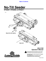
Refer to Figure 1-1:
The lead wiring harness (#10) is equipped with a 7-way
round pin connector. Make sure your tractor is equipped
with the 7-pin electrical outlet shown in Detail A before
purchasing this product.
1. Shut power machine down before dismounting.
Refer to “Power Machine Shutdown” on page 1.
2. Attach left-hand light assembly (#5) to its respective
dual light mount (#11), with four 1/4-20x1
GR5 bolts (#2), four plated flat washers (#3), and four
nylon lock nuts (#4). Tighten lock-nuts to the correct
torque, but do not overtighten. Repeat this step to
attach the right-hand light assembly (#6) to the
machine. Confirm red light covers on each light are rear
facing on the machine and to the inside of amber lights.
3. Secure enhancer module (#9) to right-side mast (#14)
with two #10-24x1 GR5 bolts (#12) and two nylon lock
nuts (#13). Refer to Detail B.
IMPORTANT: Connector (#9R) has a red wire and
connects to wire harness (#8R) on the right side of
the implement. Connector (#9L) has a yellow wire
and connects to wire harness (#8L) on the left side
of the implement.
4. Attach the connector of light wire harness (#8R)
labeled “LIGHT”, to wire harness (#6R) of the right
light assembly (#6). Now attach connector of light wire
harness (#8L) labeled “LIGHT” to wire harness (#5L)
of left light assembly (#5).
5. Connect remaining connector at opposite end of light
wire harness (#8R) labeled “ENHANCER”, to wire
harness (#9R) of the enhancer module(#9). Now
connect remaining end of light wire harness (#8L)
labeled “ENHANCER” to wire harness (#9L) of the
enhancer module (#9).
6. Connect wire harness (#9C) of enhancer module (#9)
to the matching end of 5' lead wire harness (#10).
7. Now connect the 7-way round pin connector of 5' lead
wire harness (#10) to 7-pin electrical outlet on tractor.
8. Start tractor and operate lights to verify hook-up is
operating properly:
a. Turn on headlights to verify red lights illuminate.
b. Turn on flasher lights to verify amber light are
blinking on and off.
9. If both lights operate as intended, refer to “Routing
And Securing Wires” on page 3 to safely route and
secure wiring to machine. If lights are not operating as
intended, please refer to “Check Incandescent
Lights” on page 3 to troubleshoot issue before
securing wires.
Light Kit AP-PS20
Figure 1-1
Detail A
Detail B
72114
72102

3
1/3/19
Light Kit AP-PS20 Manual No. 313-992MK
Assembly Instructions
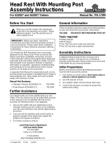
Enhance Module Wire Connections For Light Kit AP-PS20
Figure 1-2
Check Incandescent Lights
Refer to Figure 1-2:
Check dual incandescent lights to make certain they are
operating correctly.
1. It is best to have a second person available to verify
the lights are operating correctly. Start tractor and
operate lights as follows:
a. Turn on head lights to verify red lights illuminate.
b. Turn on flasher lights to verify amber lights are
blinking on and off.
2. If lights did not operate properly, recheck hook-up of
both light wire harnesses (#8), and wire harness (#10)
to enhance module (#9).
• Make sure connector (#9R) with a red wire is
connected to the right-hand wire harness (#8R).
• Make sure connector (#9L) with a yellow wire is
connected to the left-hand wire harness (#8L).
• Make sure connector on the lead wire harness
(#10) is connected to connector (#9C) on enhancer
module (#9).
3. Ensure that the 7-way round pin connector of 5' lead
wire harness is properly seated inside of 7-pin
electrical outlet on tractor.
4. Restart tractor and operate lights to verify hook-up is
now operating properly.
72126
IMPORTANT: Connectors on both 8' light wire
harnesses (#8) are labeled “LIGHT” on one end and
“ENHANCER” on the other end. Ends labeled
“LIGHT” connect to the dual incandescent lights.
Ends labeled “ENHANCER” connect to enhance
module (#9).
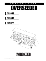
Wire Routing
Figure 1-3
Routing And Securing Wires
Refer to Figure 1-3:
After light kit assembly is complete, and the proper
operation of the lights have been confirmed, it is now time
to route and secure the wires to the machine. Proper care
in doing so will prevent wires from being snagged by
unexpected objects as well as being pinched by certain
components of the machine.
1. Starting with either light assembly, secure wire
harness (#1) to the outer hole (#2) of its respective
dual light mount with provided cable tie (#7).
2. Route the connected 8' wire harness to the wire tie
down tab (#3) on the seedbox lid end cap. Secure
wire to wire tie down tab (#3) with provided
cable tie (#7).
3. Continue routing the wire down the seedbox end
panel and secure wire with provided cable tie (#7)
to hole on seedbox end panel (#4).
4. Now move to the opposite end of 8' light wire
harness. At this end, begin routing wire connected to
enhance module (#6) to holes on the seed cup
channel (#5). Starting with inside center hole on
channel, secure wire with provided cable tie (#7),
then continue to route wire along seed cup channel,
securing wire with another cable tie at the outer most
holes.
5. At this time, gather up any excess wire and overlap
slack, securing it to the inside of seedbox end panel
with provided cable tie (#7).
6. Repeat steps 1-5 to route and secure wire harness of
second light assembly and its corresponding 8' light
wire harness.
72119

Listing of Parts
Light Kit AP-PS20 Manual No. 313-992MK 1/3/19
4
Parts Listing For Light Kit AP-PS20
Figure 2-1
Kit No. 313-992A Light Kit AP-PS20
Item Part No. Part Description Total Qty
Refer to Figure 2-1:
1 313-992A LIGHT KIT AP-PS20 (kit contains item numbers 2 through 12) - - - - - - - - - - - - - - - 1
2 802-005C HHCS 1/4-20X1 GR5 - - - - - - - - - - - - - - - - - - - - - - - - - - - - - - - - - - - - - - - - - - - 8
3 804-007C WASHER FLAT 1/4 SAE PLT - - - - - - - - - - - - - - - - - - - - - - - - - - - - - - - - - - - - - - - 8
4 803-255C NUT HEX NYLOCK 1/4-20 - - - - - - - - - - - - - - - - - - - - - - - - - - - - - - - - - - - - - - - 8
5 891-794C LEFT LIGHT ASSEMBLY LH- - - - - - - - - - - - - - - - - - - - - - - - - - - - - - - - - - - - - - - - 1
6 891-795C RIGHT LIGHT ASSEMBLY RH - - - - - - - - - - - - - - - - - - - - - - - - - - - - - - - - - - - - - - 1
7 800-060C CABLE TIE.19X14.25 3DIA 50LB - - - - - - - - - - - - - - - - - - - - - - - - - - - - - - - - - - - 14
8 891-529C LIGHT WIRE HARNESS 8' - - - - - - - - - - - - - - - - - - - - - - - - - - - - - - - - - - - - - - - 2
9 891-531C ENHANCE MODULE - - - - - - - - - - - - - - - - - - - - - - - - - - - - - - - - - - - - - - - - - - - - 1
10 891-786C LEAD WIRE HARNESS 5' - - - - - - - - - - - - - - - - - - - - - - - - - - - - - - - - - - - - - - - - - 1
11 803-268C NUT HEX NYLOCK 10-24 PLT - - - - - - - - - - - - - - - - - - - - - - - - - - - - - - - - - - - - - 2
12 842-265C HHCS #10-24X1 GR5 - - - - - - - - - - - - - - - - - - - - - - - - - - - - - - - - - - - - - - - - - - - 2
72115

1/3/19
Light Kit AP-PS20 Manual No. 313-992MK
5
Listing of Parts
This page left blank intentionally.

KUBOTA TRACTOR CORPORATION
3401 Del Amo Blvd., Torrance, CA 90503, U.S.A.
Telephone :(310)370-3370
Western Division : 1175 S. Guild Avc., Lodi. CA 95240
Telephone : (209)334-9910
Central Division : 14855 FAA Blvd., Fort Worth, TX 76155
Telephone : (817)571-0900
Northern Division : 6300 at One Kubota Way, Groveport, OH 43125
Telephone : (614)835-1100
Southeast Division : 1025 Northbrook Parkway, Suwanee, GA 30024
Telephone : (770)995-8855
/