Page is loading ...

DESCRIPTION
The HAF-505, 55 CFM filter is designed to
remove dirt, pipe scale and liquid aerosol.
It includes a 0.01 micron filter element and
automatic mechanical drain.
(Optional)
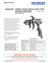
Figure 1 HAF-505 & HAF-511 55 CFM Air Filter
PARTS LIST
Ind.
Ref No. Replacement Parts
No. Part No. Description Required
1 HAF-404 Filter Change Indicator 1
(not shown)
1A --- Cover 1
2 --- O-Ring 1
3 HAF-28 Filter and O-Ring Kit 1
4 HAF-18 Automatic Drain 1
(Standard)
5 HAF-8 Plastic Bowl 1
6 HAF-19 Metal Bowl Guard 1
7 HAF-409 Clamp Ring 1
8 --- 1/2 x 3/8 Vinyl Tubing 6' 1
9 HAF-11 Manual Drain (Optional) 1
5
6
8
7
4
3
2
1A
1 (not shown)
SPECIFICATIONS
Air Filter:
Air Inlet 1/2" NPT(F)
Air Outlet 1/2" NPT(F)
Air Flow Capacity 55 CFM
Maximum Inlet Pressure 150 PSIG (10.3 Bar)
Maximum Operating Pressure 150 PSIG (10.3 Bar)
Maximum Temperature 150° F (65.6°C)
Filter 0.01 Micron
Risk of personal injury.
Risk of property damage.
Except as otherwise specified by the
manufacturer, this product is specifi-
cally designed for compressed air ser-
vice and use with any other fluid
(liquid or gas) is a misapplication. For example,
use with or injection of certain hazardous gases
in the system (such as oxygen or liquid petro-
leum gas) could be harmful to the unit or result
in a combustible condition that may cause
fire or explosion. Manufacturer’s warranties
are void in the event of misapplication and
manufacturer assumes no responsibility for
any resulting loss.
INSTALLATION
Risk of injury. Do not place unit in service
without metal bowl guard installed. Filter
units are sold only with metal bowl guards.
To minimize the danger of flying fragments
in the event of plastic bowl failure, guard
must not be removed. If the unit is in service
without the metal bowl guard installed,
manufacturer's warranties are void and the
manufacturer assumes no responsibility for
any resulting loss. If unit has been in service
and does not have a metal bowl guard, order
one and install before placing back in service.
Certain solvents, paints and chemicals may
attack plastic bowl and can cause bowl failure.
Do not use near these materials.
PROP 65 WARNING
WARNING: This product
contains chemicals
known to the State of
California to cause
cancer and birth defects or other
reproductive harm.
CA PROP
65
HAF-505
55 CFM COALESCING FILTER
SB-6-152-R1 (2/2018) 1 / 4 www.carlisleft.com
EN
SERVICE MANUAL

INSTALLATION (continued)
1. Be sure to read all "Warnings" and
"Cautions" in this manual and on the
unit before installation or using this
equipment.
2. Install filter as close as possible to point
where air is being used. Install main air
shut-off valve and standard pipe union
(supplied by user) upstream of filter to
allow maintenance to unit.
3. Install unit with air flow through filter
in direction of arrow on top of unit.
4. Minimum 1/2" piping is recommended.
Avoid using fittings, couplings, etc.
that restrict air flow.
5. Mount filter in a vertical position.
6. Do not install filter in an application
where the pressure drop will exceed
20 psi. For example, a quick opening
valve located upstream from the filter
could cause a momentary pressure
drop in excess of 20 psi.
7. Maximum inlet pressure and operating
temperature is: 150 PSIG (10.3 bar) and
150° F (65.6° C).
8. A 6' length of vinyl tubing is shipped
loose with the unit. Slide over automatic
drain which protrudes from bottom of
bowl. Place other end of vinyl tubing
into appropriate receptable (i.e. be-
low booth grating, can, etc.). Prevent
vinyl tubing from becoming kinked
which would prevent free movement
of liquids discharged from the auto-
matic drain.
9. An optional manual drain (HAF-11) can
be installed in place of the automatic
drain.
OPERATION
After the unit is installed and ready to use;
1. Attach air hose(s) to outlet ball valve(s),
selecting regulated and/or non-regulated
according to the application (not sup-
plied).
2. Open main shut-off valve upstream of
filter.
3. Open ball valve(s) (not supplied) to sup-
ply air to spray gun or tool being used.
4. After use, shut off ball valve(s) and bleed
off residual air in hose(s).
Note
The filter change indicator only oper-
ates when air is flowing. It will always
be green when there is no flow.
MAINTENANCE
Certain solvents, paints and chemi-
cals may attack plastic bowl and
can cause bowl failure. Do not use
near these materials. When bowl
becomes dirty, wipe only with a
clean, dry cloth. Immediately re-
place any crazed, cracked, damaged
or deteriorated plastic bowl with a
new plastic bowl. Reinstall metal
bowl guard.
Risk of injury. Components under
pressure. Relieve air pressure before
performing maintenance.
1. Before performing maintenance on
unit, close main shut-off valve located
upstream of filter. Bleed off residual air
in unit.
2. To open filter, press button located on
clamp ring and rotate ring either clock-
wise or counterclockwise while pulling
down on ring. The metal bowl guard and
plastic bowl can then be removed from
the filter head.
3. Remove the filter element by loosening
counterclockwise. Clean or replace the
filter element. Frequency of element
replacement will depend upon air
quality, air usage, and condition of the
air piping. It is recommended to check
the element change indicator daily, and
replace when indicator turns red.
4. Inspect o-ring for damage. Replace if
necessary.
5. Inspect plastic bowl for signs of damage
such as cracks, crazing or deterioration.
Replace if necessary. See "Caution" in
column 2.
Risk of injury. Do not place unit in
service without metal bowl guard
installed.
6. Before placing unit back into service,
make sure plastic bowl and metal bowl
guard are properly installed and securely
locked in place.
7. Confirm automatic drain operates prop-
erly after unit is in operation. Refer to
Service Bulletin SB-6-149 which provides
automatic drain service information.
Replace if necessary.
ACCESSORIES
HAF-407
CleanAir™ Mounting Bracket
Assembly Kit
EN
SB-6-152-R1 (2/2018)2 / 4www.carlisleft.com

NOTES
EN
SB-6-152-R1 (2/2018) 3 / 4 www.carlisleft.com

EN
SB-6-152-R1 (2/2018)4 / 4www.carlisleft.com
WARRANTY POLICY
This product is covered by Carlisle Fluid Technologies’ materials and workmanship limited warranty.
The use of any parts or accessories, from a source other than Carlisle Fluid Technologies,
will void all warranties. Failure to reasonably follow any maintenance guidance provided
may invalidate any warranty.
For specic warranty information please contact Carlisle Fluid Technologies.
For technical assistance or to locate an authorized distributor,
contact one of our international sales and customer support locations.
Region Industrial/Automotive Automotive Renishing
Americas
Tel: 1-800-992-4657 Tel: 1-800-445-3988
Fax: 1-888-246-5732 Fax: 1-800-445-6643
Europe, Africa,
Middle East, India
Tel: +44 (0)1202 571 111
Fax: +44 (0)1202 573 488
China
Tel: +8621-3373 0108
Fax: +8621-3373 0308
Japan
Tel: +81 45 785 6421
Fax: +81 45 785 6517
Australia
Tel: +61 (0) 2 8525 7555
Fax: +61 (0) 2 8525 7575
Carlisle Fluid Technologies is a global leader in innovative nishing technologies.
Carlisle Fluid Technologies reserves the right to modify equipment specications without prior notice.
DeVilbiss
®
, Ransburg
®
, ms
®
, BGK
®
, and Binks
®
are registered trademarks of Carlisle Fluid Technologies, Inc.
©2018 Carlisle Fluid Technologies, Inc.
All rights reserved.
For the latest information about our products, visit www.carlisleft.com
/