DeVilbiss HAF-601 User manual

Type
User manual

This manual is also suitable for

HAF-601 (13-0087) Air Station
SB-6-132-G
Replaces SB-6-132-F
IMPORTANT: Read and follow all INSTRUC-
TIONS and SAFETY PRECAUTIONS before
installing, operating or maintaining this
equipment. Keep this manual for future
reference.
SPECIFICATIONS
(1) Air Filter (Separator): 13-0041
Air Inlet Thread 1/2" NPT(F)
Air Outlet Thread 1/2" NPT(F)
Air Flow Capacity 100 CFM
Max. Temperature 150° F (65.6° C)
Max. Inlet Pressure 150 PSIG
Auto. Mechanical Drain Supplied
Filter Element 5 Micron
(2) Coalescing Filter: HAF-505
Air Inlet Thread 1/2" NPT(F)
Air Outlet Thread 1/2" NPT(F)
Air Flow Capacity 55 CFM
Max. Inlet pressure 150 PSIG
Max. Operating Pressure 150 PSIG
Max. Temperature 150° F (65.6° C)
Auto. Mechanical Drain Standard
Filter Element 0.01 Micron
(3) Charcoal Filter: HAF-517
Air Inlet Thread 1/2" NPT(F)
Air Outlet Thread 1/2" NPT(F)
Air Flow Capacity 75 CFM @
100 PSI
Max. Operating Pressure 150 PSIG
(10.3 Bar)
Max. Temperature 150° F (65.6° C)
Manual Mechanical Drain Standard
Pressure Differential
Indicator Standard
Aerosol Filter .003 ppm./wt.
Particulate Filter 3.0 micron
(4) Flow-Thru Regulator: HAR-508
Flow-Thru Ports 1/2" NPT(F)
Regulated Ports 1/4" NPT(F)
Air Flow Capacity, 28 CFM @
60 PSI
Regulated Ports With 100 PSI
Inlet
Max. Temperature 175° F (79.4° C)
Max. Inlet Pressure 300 PSIG
Regulator Range 0-125 PSIG
(5) Tool Air Regulator: HAR-507
Air Inlet Port 3/8" NPT(F)
Air Outlet Port 1/4" NPT(F)
(3 ea.)
Air Flow 60 CFM
Max. Temperature 120° F (65.6° C)
Max. Inlet Pressure 150 PSIG
Regulator Range 0 to 125 PSIG
DESCRIPTION -– AIR STATION
All components in Figure 1 are included
with the air station. This unit is designed
to provide a source of clean, filtered air for
the connection of both a DeVilbiss supplied
air respirator and a paint spray gun. The
unit removes dirt, pipe scale, water, oil,
Service Bulletin
Risk of explosion or fire. Improper use
can cause personal injury.
• This product is designed and
intended for use in industrial
compressed air systems only.
Do not use for liquids or gasses
other than air.
• Donotusewherepressureortem-
peraturecanexceedratedoperating
conditions(seespecications).
• Regulated outlet pressure must
never be set higher than the
maximum operating pressure of the
downstreamairtoolorequipment.
An outlet pressure gauge should
alwaysbeused.
2
5
4
3
1
Figure 1
liquid aerosols, hydrocarbons and odors.
One regulated port is provided for the
connec tion of a DeVilbiss breathable air
supply hose. A separate regulated port is
fitted with a 1/4" NPS(M) hose connection
for spraying applications.
BREATHING AIR REQUIREMENTS
Supplied breathing air, as defined by
OSHA 29 CFR 1910.134i and NIOSH 42 CFR
84.141, MUST meet or exceed the following
requirements for Type 1-Grade D breathable
air, as defined in Compressed Gas Associa-
tion (CGA-G7-1-1997):
Oxygen = 19.5-23.5% (Typical
atmospheric levels)
Oil(condensed) = 5 mg/m (milligrams
per cubic meter) maximum
Carbon Monoxide (CO) = 10 ppm
(parts per million) max.
Carbon Dioxide (CO
2
) = 1000 ppm
(parts per million) max. (Typical
atmospheric levels)
Odor = The presence of a pronounced
odor should render the air as
unsatisfactory
It is up to the employer to assure that the
air compressor is properly maintained,
that the air compressor intake is located
in a clean contaminate free location
and that the air compressor is drawing
in typical atmospheric air, meeting all of
the national and local requirements for
breathing air.
ThislterunitdoesnotremoveorlterCar-
bonMonoxide(CO). It is up to the employer
to ensure that the level of CO does not exceed
the maximum national or local allowed level.
The recommended method to assure that the
CO level is not exceeded is to install a carbon
monoxide monitor and alarm.
This filter unit will only remove particu-
latematter,water,oilandodor. This filter
unit will meet the particulate matter, oil
and odor requirements of Type 1-Grade D
Breathable Air and Compressed Breathing
Air, CSA-Z180.1 when:
• The lter unit is connected to a
compressed air source:
The compressor is properly
maintained
The air compressor intake is
located in a clean contaminate
free location
The air compressor is drawing
in typical atmospheric air,
meeting all of the national
and local requirements for
breathing air
• The lters are properly maintained
A properly operating CO monitor
is installed
PAGE 2 SB-6-132-G
receptacle. Prevent vinyl tubing from
becoming kinked which would prevent
free movement of liquids discharged
from the automatic or manual drain.
8. An optional manual drain HAF-11) can
be installed in place of the automatic
drains.
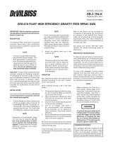
INSTALLATION – MOUNTING BRACKETS
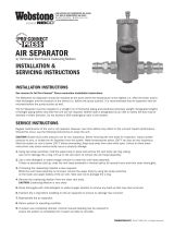
1. Use the mounting bracket as a template
for locating the mounting holes.
2. Drill appropriate sized holes through
booth wall as shown in Figure 2. Two
5/16" round head screws, nuts and lock-
washers are supplied. If mounting into
a solid or hollow wall, use anchors (not
included).
3. Assemble mounting bracket to wall,
positioning “L” bracket with top screw.
4. Tighten bottom screw firmly. Leave top
screw partially loose so “L” bracket can
slide up out of the way.
5. Place filter in the bracket, positioning
between curved saddle ears. See Figure
1 on Page 1.
6. Slide “L” bracket down against top of
filter, then firmly tighten the top screw.
SAFETY PRECAUTIONS
This manual contains important information that all users must know and understand before using the equipment. This information
relates to USER SAFETY and PREVENTING EQUIPMENT PROBLEMS.
To help you recognize this information, we use the following terms to draw your attention to certain equipment labels and portions of
this manual. Please pay special attention to any label or information that is highlighted by one of these terms:
Note
Information that you should pay
special attention to.
Important information that tells
how to prevent damage to equip-
ment,orhowtoavoida situation
that might cause minor injury.
Important information to alert
you to a situation that might cause
serious injury if instructions are not
followed.
INSTALLATION – AIR STATION
Riskofexplosionandinjury.Release
all air pressure from system before
servicing system. Be sure to read
andunderstandallServiceBulletins
on the separate components before
usingthesystem.Useonlyspecied
DeVilbiss parts.
Riskofequipmentdamage!Donot
install your air station where it is
subjected to sudden depressuriza-
tioncyclesexceeding20PSIG.Quick
relievingairsolenoidvalves,typical
in some spray booths, will eventually
failpressuregaugesandlters.
To minimize sudden depressurization effect,
replace the existing solenoid with a "slow
closing solenoid valve". (One source: Auto-
matic Switch Co). Or, install an air adjusting
valve at the existing solenoid valve outlet.
For ease of installation and maintenance,
attach the assembled air station to the main
air line using a pipe union, (not included).
1. Be sure to read all Warnings and Cautions
in this manual and component manuals
on the unit before installation or using
this equipment.
2. Install air station system as close as pos-
sible to the point where the air is being
used. Use enclosed mounting bracket
to support Air Station.
3. Install main shut-off valve (supplied by
user) upstream of air drying system to
allow maintenance to the unit.
4. Install unit with air flow through filter in
direction of arrow on top of filters.
5. Minimum 3/4" NPT piping is recom-
mended. Avoid using fittings, couplings,
etc. that restrict air flow.
6. Maximuminletpressureandoperating
temperature is: 150 PSIG and 120° F
(48.9 C)
7. Three 6' lengths of vinyl tubing are
shipped loose with the system. Slide
over drains which protrude from bot-
tom of the filters. Place the other
end of vinyl tubing into appropriate
Figure 2 – Mounting Bracket
5/16" Nuts
5/16"
Rd. Hd.
Machine
Screws
“L” Bracket
5/16" Lockwashers
Booth Wall
Mounting Bracket
Riskofillnessordeath.Carbonmon-
oxidecancausenausea,faintingor
death.Stopusingifcarbonmonoxide
ispresent.Thisunitdoesnotremove
carbonmonoxide.Acarbonmonox-
idemonitorshouldbeincorporated
into your air supply line to warn of the
presenceofcarbonmonoxide.
Risk of injury. Do not place unit in
service without metal bowl guard
installed. Filter units are sold only
withmetalbowlguards.Tominimize
thedangerofyingfragmentsinthe
eventofplasticbowlfailure,guard
mustnotberemoved.Iftheunitis
in service without the metal bowl
guardinstalled,manufacturer’swar-
rantiesarevoidandthemanufacturer
assumes no responsibility for any
resulting loss. If unit has been in
service and does not have a metal
bowl guard, order one and install
before placing back in service.
Certain compressor oils, cleaning
agentsandsolventsmayattackthe
plasticandrubbercomponentsused
intheconstructionofthisproduct.
Thisproductshouldnotbeusedin
conjunction with or in the vicinity
ofthesematerials.Readandfollow
material labels carefully. Please
consultDeVilbissifindoubt.
SB-6-132-G Page 3
OPERATION – AIR STATION
After the system is installed and ready to
use:
1. Attach breathable air hose to connection
on flow-through regulator.
2. Attach spray air hose to outlet ball valve
on spray gun regulator.
3. Open main shut-off valve upstream of
system.
4. Attach breathable air hose to supplied
air respirator. Adjust pressure on flow-
through regulator to 60 PSIG (flowing).
The pressure should never be allowed
to drop below 50 PSI in a flowing condi-
tion.
5. Open ball valve to supply air to spray
gun or tool being used. With air flowing,
adjust air pressure to desired setting.
MAINTENANCE – COALESCING FILTER
HAF-505
1. Before performing maintenance on unit,
close any main shut-off valve located
upstream of filter. Bleed off residual air
in unit.
2. To open filter, press button located on
clamp ring and rotate ring either clock-
wise or counterclockwise while pulling
down on ring. The metal bowl guard
and plastic bowl can then be removed
from the filter body.
3. Remove the filter element by loosening
counterclockwise. Clean or replace the
filter element. Frequency of element
replacement will depend upon air quality,
air usage and condition of the air piping.
It is recommended to check the element
change indicator daily and replace ele-
ment when indicator turns red.
4. Inspect “O” ring for damage. Replace
if necessary.
5. Inspect plastic bowl for signs of damage
such as cracks, crazing or deterioration.
Replace if necessary.
Note
6. The filter change indicator only operates
when air is flowing. It will always be
green when there is no air flow.
HAF-505 Parts List
Ind.
Ref. Replacement Parts
No. Part No. Description Req.
1 HAF-404 Filter Change Ind. 1
(Not shown)
1A Body 1
2 “O” Ring 1
3 HAF-28 Filter & “O” Ring Kit 1
4 HAF-18 Automatic Drain 1
5 HAF-8 Plastic Bowl 1
6 HAF-19 Metal Bowl Guard 1
7 HAF-409 Clamp Ring 1
Figure 4 – HAF-505
1A
1 (Indicator
Not shown)
2
3
4
7
6
5
HAF-8
Transparent
Plastic Bowl
HAF-6
Filter Kit
(Includes Bowl
“O” Ring
HAF-19
Metal Bowl
Guard
HAF-409
Clamp Ring
HAF-18
Automatic Drain
(Available sepa-
rately)
HAF-26
Element
Retainer
Gasket
(Included
with HAF-26)
Baffle
(Included with
HAF-26)
HAF-17
Bowl
“O” Ring
Body
(Not Available)
Figure 3 – 13-0041
HAF-11
Flexible Drain
(supplied with
13-0041)
MAINTENANCE – WATER SEPARATOR
FILTER 13-0041
1. Before performing maintenance on unit,
close any main shut-off valve located
upstream of filter. Bleed off residual air
in unit.
2. To open filter, press button located on
clamp ring and rotate ring either clock-
wise or counterclockwise while pulling
down on ring. The metal bowl guard
and plastic bowl can then be removed
from the filter body.
3. Remove the filter element by loosening
counterclockwise. Clean or replace the
filter element. Frequency of element
replacement will depend upon air quality,
air usage and condition of the air piping.
It is recommended to change the element
every six months.
4. Inspect “O” ring for damage. Replace
if necessary.
5. Inspect plastic bowl for signs of damage
such as cracks, crazing or deterioration.
Replace if necessary.
PAGE 4 SB-6-132-G
MAINTENANCE – HAF-517
CHARCOAL FILTER
1. Before performing maintenance on unit,
close any main shut-off valve located
upstream of filter. Bleed off residual air
in unit.
2. To open filter, press button located on
clamp ring and rotate ring either clock-
wise or counterclockwise while pulling
down on ring. The metal bowl guard
and plastic bowl can then be removed
from the filter body.
3. Remove the filter element by loosening
counterclockwise. Clean or replace the
filter element. Replace the charcoal
element when it no longer removes oil
vapor odors or when the red indicator is
visible.
4. Inspect "O" ring for damage. Replace if
necessary.
5. Inspect plastic bowl for signs of damage
such as cracks, crazing or deterioration.
Replace if necessary.
MAINTENANCE – AIR PRESSURE
REGULATOR HAR-507
1. Occasionally remove bottom plug (7) and
clean valve seat (11) and body. Clean
parts with denatured alcohol, wipe off
seat and blow out body with compressed
air.
2. To disassemble regulator, remove
screws, bonnet, spring and spring but-
ton. Diaphragm assembly can now be
removed.
3. Check all O-rings for signs of damage.
Replace if necessary.
4. Reassemble parts. Insert stem of valve
through hole in regulator body. Install
spring and o-rings. Screw bottom plug
into body.
Note
Erratic operation or loss of regulation
is usually due to dirt in the valve area
and cleaning is necessary. If cleaning
does not correct the problem, replace
the items included in Repair Kit KK-
4977. If unit leaks air at A , install
Repair Kit KK-4977.
Figure 6 – HAR-507
HAF-517 Parts List
Ind.
Ref. Replace. Parts
No. Part No. Description Req.
1 HAF-404 Filter Change Ind. 1
(Not shown)
1A --- Body 1
2 --- “O” Ring 1
3 HAF-36 Filter Element and 1
"O" ring Kit
4 HAF-11 Manual Drain 1
5 HAF-8 Plastic Bowl 1
6 HAF-19 Metal Bowl Guard 1
7 HAF-409 Clamp Ring 1
Figure 5 – HAF-517
Ind.
Ref. Replace. Parts
No. Part No. Description Req.
1 #10-32x9/16 Fillister 6
Hd. Screw
2 HAR-14 Cover 1
3 Spring Button 1
4 Diaphragm Spring 1
5 Body 1
6 Pipe Plug 1/4" NPT(M) 1
7 Bottom Plug 1
8 KK-4977 Repair Kit (includes 1
Items 9 thru 14)
9 Diaphragm Assy. 1
10 O-Ring 1
11 Valve 1
12 O-Ring 1
13 Spring 1
14 O-Ring 1
PARTSLIST–ModelHAR-507RegulatorAssy.
14
13
9
10
11
12
6
5
8
1 (not shown)
4
5
6
7
1A
3
2
1
2
3
4
7
A
SB-6-132-G Page 5
MAINTENANCE –
FLOW-THRU REGULATOR
Do not submerge regulator or com-
ponents in solvent or use solvent to
clean regulator parts. Damage may
occurtoregulatorandcomponents.
Useaclothdampenedinwarm,soapy
water to clean exterior of regulator.
Note
This unit may be serviced without
removing the unit from the com-
pressed air line.
1. Frequency of servicing depends largely
on the condition of the compressed air
system and the degree of contamination
in the system.
2. Before attempting to service this product
in-line, depressurize both the upstream
and downstream sides of regulator.
3. Remove the bottom plug, valve spring
and valve assembly. Inspect all seals
and components for damage and
replace as required. Clean seals and
components with mild detergent and
water. Use a clean, dry cloth to wipe
any contamination from valve seal inside
the body. Lubricate the valve stem and
lower valve O-ring seal with a light coat
of MAGNALUBE-G or similar lubricant.
Reassemble. Bottom plug torque should
not exceed 25 in./lbs. (2.8 N-m).
4. To replace main spring or diaphragm,
turn adjusting knob counterclockwise
to remove all spring force, then remove
bonnet. Remove the adjusting screw
assembly, main spring, slip ring and
diaphragm assembly. Inspect the dia-
phragm and the relief seat for damage
and contamination. Replace diaphragm
assembly if necessary. Clean the relief
seat with a soft dry cloth. Reassemble
in reverse order making sure the slip
ring is properly positioned on top of the
diaphragm. Bonnet torque should not
exceed 120 in./lbs. (13.6 N-m).
Figure 7 – HAR-508 Regulator
5. Before returning unit to service, ensure
that all seals have been properly rein-
stalled or replaced and components re-
quiring torque values have been properly
set.
6. If regulated pressure begins to creep (an
uncontrolled rise in regulated pressure),
it will most likely be caused by contami-
nation on the valve seat.
7. If the unit leaks from the vent holes in the
bonnet, it may be caused by contamina-
tion, deterioration or damage to the valve
seat or diaphragm relief seat. Replace
any damaged or worn components.
Knob
Panel
Nut
Bonnet
*Thrust
Washer
*Adjusting
Screw
Assembly
*Main
Spring
*Slip
Ring
*Diaphragm
Assembly
*Valve
Assembly
Body
Assembly
*Valve
Spring
Bottom
Plug
*Bottom
Plug
O-Ring
Body
Cover
* KK-5045 Diaphragm Repair Kit
PAGE 6 SB-6-132-G
Rubber
Seal
6. Insure rubber seal is in place in the
center of the flat stem (See Figure 11).
If the seal comes out, press it back in
place in the recess of the stem.
7. Replace the float cap (again, be certain
the rubber seal, Figure 11, is in place).
8. Slide float over float guide.
9. Snap float cover onto bottom piece.
10. Install automatic drain into bowl. Be
sure O-ring is in place (between the
drain and bowl). Tighten the plastic
retaining nut firmly by hand.
11. Monitor the automatic drain for proper
operation. If it fails to operate properly,
replace with a new unit.
Note
If the Float Guide inadvertently
came apart, refer to Figure 12 and
instructions.
3. Slide flat off flat guide (See Figure 9).
4. Using a knife edge, carefully pry off
flat cap (See Figure 10).
5. Clean inside of flat. Remove all traces
of water or dirt.
Note
The automatic drain includes a float.
If water gets into the float, the auto-
matic drain may not function properly.
Under normal conditions, water will
not enter the float. However, water
can get in the float if the filter bowl
is washed with the drain installed or
if air line contamination causes the
drain mechanism to stick.
You can confirm the automatic drain is not
operating if the water level in the plastic
bowl is higher than the top of the automatic
drain.
To remove water from the float, follow these
instructions. Be careful not to lose or damage
any internal parts of the automatic drain (re-
placement parts are not available - complete
drain replacement will be necessary).
1. Remove automatic drain from plastic
bowl by loosening plastic retaining
nut. Keep retaining nut and O-ring for
reassembly later.
2. Using a knife edge, carefully pry apart
the float cover and bottom piece (See
Figure 8).
HAF-18 Automatic Drain
(Inside view of float)
Cap
Figure 10
Float Guide
Float
Figure 9
Float Cover
Bottom Piece
Figure 8
Figure 11
Float
Stem
Note–FloatGuide
Be sure to reassemble all parts as
shown into the float guide. Snap float
guide cover into bottom piece.
Small
Spring
Float
Guide
Cover
Bottom
Piece
Large
Spring
Actuator
Pin
Flat view of
Spring Disc
Figure 12
Pry apart with knife edge.
SB-6-132-G Page 7
5 First air drop should be at least 25' from the compressor, al-
though 50' is optimum. This allows the compressed air to cool
so any condensation can occur before it gets to the air filter.
6 Shut-off valves are installed before the point of use filter. This
allows air to be shut off for filter maintenance.
7 Point-of-use filter - Strongly recommended for eliminating
any remaining contaminates. The DeVilbiss CleanAir
type air control units are most effective in providing a truly
contaminant-free air supply.
8 Drain valve - The daily draining of the system at each outlet
disposes of the contaminants that build up in the air supply.
9 Drain the compressor trap daily if equipped with a manual
drain.
Proper maintenance of the air compressor can reduce airborne con-
taminants such as particles and oils, and reduce heat and operating
cost. Check air filters, oil level and perform regular maintenance
per operators manuals.
CLEANAIR™ AIR PIPING RECOMMENDATIONS
The plumbing of your shop air lines is very important. Correct
installation is necessary for the proper performance of your equip-
ment for an uncontaminated air supply and for sufficient pressure
to your breathing apparatus and spray gun.
Correct air line piping is so important that this one factor alone
can reduce contaminates in your air supply up to 75%. Reducing
contaminates to the filter also reduces the frequency of filter replace-
ment, maintenance, and of course reduces the risk of contaminates
to the painter and paint supply.
Even the size of the pipe is critical. Using pipe that is too small in
diameter can cause a pressure drop.
Example: If an air compressor delivers 100 psi through a 100'
pipe 1/2" in diameter, there's greater pressure drop than if a 3/4"
diameter pipe were used. The chart on the back page provides
recommended piping sizes.
AIR LINE PIPING GUIDE
1 After leaving the air compressor, the air line should go straight
up as high as possible. This helps prevent any water from
leaving the compressor and travelling through the pipe.
2 Horizontal pipes should slope back towards the compressor at
least 4" per 50'. As warm air leaves the compressor, it cools
and thereby water vapor condenses as it travels through the
pipe. This water, a problem in itself, also can cause scaling
and rust inside the piping. The backward sloping of the pipe
helps drain these contaminates back toward the compressor
drain which should be drained daily.
3 A take off should come from the top of the main air supply
line at each air drop. This reduces the risk of water and other
contaminates from traveling down the drop into the water
separator.
4 Pipe diameter must be of sufficient size for the volume of air
being passed as well as the length of pipe used. This will
minimize pressure drop. See chart.
MINIMUM PIPE SIZE RECOMMENDATIONS CHART
Compressor Compressor Main Min. Pipe
Size Capacity AirLine Diameter
1-1/2 & 2 HP 6 to 9 CFM Over 50 ft. 3/4"
3 & 5 HP 12 to 20 CFM Up to 200 ft. 3/4"
Over 200 ft. 1"
5 to 10 HP 20 to 40 CFM Up to 100 ft. 3/4"
100 to 200 ft. 1"
Over 200 ft. 1-1/4"
10 to 15 HP 40 to 60 CFM Up to 100 ft. 1"
100 to 200 ft. 1-1/4"
Over 200 ft. 1-1/2"
1
6
3
5
8
3
2
7
7
6
9
8
For normal
compressed
air systems
having average
amounts of
airborne con-
taminants.
Add final
drain leg for
extremely
wet/dirty air.
Add drain leg with
blow down valve at
each station when
compressed air is
extremely wet/dirty.
Figure 13 – CleanAir™ Piping
4
8
PAGE 8 SB-6-132-G
WARRANTY
This product is covered by DeVilbiss’s 1 Year Limited Warranty.
Your DeVilbiss Air Station is warranted to be free of defects in
materials and workmanship for a period of one year from date of
original purchase. This warranty does not cover failures resulting
from abuse, improper maintenance, misuse, or normal wear. If
found to be defective during the warranty period, DeVilbiss will at
it’s own option, either repair or replace the product. THERE IS NO
OTHER EXPRESS WARRANTY. IMPLIED WARRANTIES, INCLUDING
THOSE OF MERCHANTABILITY AND FITNESS FOR A PARTICULAR
PURPOSE ARE LIMITED TO A TWELVE MONTHS FROM PURCHASE
AND TO THE EXTENT PERMITTED BY LAW ANY AND ALL IMPLIED
WARRANTIES ARE EXCLUDED. THIS IS THE EXCLUSIVE REMEDY,
AND LIABILITY OR CONSEQUENTIAL AND INCIDENTAL DAMAGES
UNDER ANY AND ALL WARRANTIES IS EXCLUDED TO THE EXTENT
EXCLUSION IS PERMITTED BY LAW. Some states do not allow
limitations on how long an implied warranty lasts, or the limitations
or exclusion of consequential or incidental damages, so the above
limitations or exclusions may not apply to you.
ACCESSORIES
HAF-407
Clean Air Mounting
Bracket Assembly Kit
IndustrialFinishing
DeVilbiss has authorized distributors throughout the world. For tech-
nical assistance or the distributor nearest you, see listing below.
U.S./CanadaTechnicalServiceOffice:
195 Internationale Blvd., Glendale Heights, IL 60139
Toll-Free Telephone: 1-888-992-4657 (U.S.A. and Canada only)
Toll-Free Fax: 1-800-368-8401
DeVilbissWorldwideSalesandServiceListing:www.devilbiss.com
10/08 ©2008 Inc. All rights reserved. Printed in U.S.A.
DeVilbiss Automotive Refinishing
DeVilbiss has authorized distributors throughout the world.
For equipment, parts and service, check the Yellow Pages
under “Automotive Body Shop Equipment and Supplies.”
For technical assistance, see listing below.
U.S./CanadaCustomerServiceOfce:
11360 S. Airfield Road, Swanton,OH 43558
Toll-Free Telephone: 1-800-445-3988 (U.S.A. and Canada only)
Toll-Free Fax: 1-800-445-6643
  • Page 1 1
  • Page 2 2
  • Page 3 3
  • Page 4 4
  • Page 5 5
  • Page 6 6
  • Page 7 7
  • Page 8 8

DeVilbiss HAF-601 User manual

Type
User manual
This manual is also suitable for

Ask a question and I''ll find the answer in the document

Finding information in a document is now easier with AI