Page is loading ...

IMPORTANT! DO NOT DESTROY
It is the Customer's responsibility to have all operators and service personnel read and understand this manual.
Contact your local DeVilbiss representative for additional copies of this manual.
READ ALL INSTRUCTIONS BEFORE OPERATING THIS DEVILBISS PRODUCT.
DAD-500 (130026)
DESICCANT AIR DRYING SYSTEM
SB-6-156-R1 (3/2018) 1 / 8 www.carlisleft.com
EN
SERVICE MANUAL

CA PROP
65
PROP 65 WARNING
WARNING: This product contains chemicals known
to the State of California to cause cancer and birth
defects or other reproductive harm.
Ref. Replacement Individual
No. Part No. Description Parts Req.
1 13-0041 Water Separator Filter 1
(HAF-502)
2 HAF-505 Oil Coalescing Filter 1
3 --- Desiccant Dryer 1
4 HAR-507 Air Regulator 1
5 GA-288 Gauge 1
6 VA-542 Ball Valve 1
*7 DAD-1 Replacement Desiccant
(Not shown)
1
(1 Humidity Indicator Paper
Included)
8 DAD-8 Air Filter, (inside of tank) 2
9 DAD-400 Humidity Indicator (1 Humidity 1
Indicator Paper Included)
10 PT-417 Desiccant Tank (without desiccant) 1
(Includes Ref. No. 8)
11 HAF-404 Filter Change Indicator 1
12 DAD-600 Dessicant Tune-Up Kit
(Not shown)
1
Includes 1 each: DAD-1 and HAF-6.
13 DAD-600-1 Complete Tune-Up Kit
(Not shown)
1
Includes 1 each: DAD-1, HAF-28,
and HAF-6.
14
SSG-8217-K2
O-Ring Kit (2) 1
15 PT-96 Pipe Plug, Special, 1-1/2 NPT 2
16 VA-595 Main Air Supply Shut Off Valve 1
(Not shown)
*The Safety Data Sheet (SDS) is available upon request.
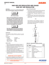
Figure 1
DAD-500 25 CFM Desiccant Air Dryer
DESCRIPTION
The 25 CFM DAD-500 Desiccant Air Drying System
is designed to be a point of use system. It is capable
of removing dirt, water, oil and water vapor from
compresssed air. It consists of a filter separator,
coalescing filter, desiccant dryer, air regulator and main
air supply shut off valve.
SPECIFICATIONS
13-0041 (HAF-502) Water Separator Filter - See page 4:
Air Inlet 1/2" NPT(F)
Air Outlet 1/2" NPT(F)
Air Flow Capacity 100 CFM
Maximum Operating Pressure 150 PSIG (10.3 Bar)
Maximum Temperature 150° F (65.6°C)
Automatic Drain Standard
Filter 5 micron
HAF-505 Oil Coalescing Filter - See page 5:
Air Inlet 1/2" NPT(F)
Air Outlet 1/2" NPT(F)
Air Flow Capacity 55 CFM
Maximum Operating Pressure 150 PSIG (10.3 Bar)
Maximum Temperature 150° F (65.6°C)
Automatic Mechanical Drain Standard
Pressure Differential Indicator Standard
Filter 0.01 Micron
Desiccant Dryer - See page 3:
Air Inlet 1/2" NPT(F)
Air Outlet 1/2" NPT(F)
Air Flow Capacity 25 CFM
Maximum Operating Pressure 150 PSIG (10.3 Bar)
Maximum Temperature 150° F (65.6°C)
Humidity Indicator Standard
Water Vapor Removal -40° F Dew Point
HAR-507 Air Regulator - See page 5:
Air Inlet 3/8" NPT(F)
Air Outlet 1/4" NPT(F) (3 ea.)
Air Flow 60 CFM
Maximum Operating Pressure 150 PSIG (10.3 Bar)
Maximum Temperature 120° F (65.6°C)
VA-595 Main Air Supply Shut Off Valve - Not Shown:
Air Inlet and Air Outlet 1/2" NPT(M)
Maximum Operating Pressure 175 PSIG (12.0 Bar)
Shipping Weight: DAD-500 = 35 lbs.
PARTS LIST
Air In
1
4
6
Air Out
5
8
3
2
8
10
9
11
14
14
15
15
EN
SB-6-156-R1 (3/2018)2 / 8www.carlisleft.com

Risk of personal injury.
Risk of property damage.
Except as otherwise specified by
the manufacturer, this product
is specifically designed for com-
pressed air service and use with
any other fluid (liquid or gas) is a
misapplication. For example, use
with or injection of certain hazard-
ous gases in the system (such as
oxygen or liquid petroleum gas)
could be harmful to the unit or
result in a combustible condition
that may cause fire or explosion.
Manufacturer's warranties are
void in the event of misapplication
and manufacturer assumes no re-
sponsibility for any resulting loss.
INSTALLATION
Risk of injury. Release all air pres-
sure from system before servic-
ing system. Be sure to read and
understand all Service Bulletins on
the separate components before
using the system. Use only speci-
fied DeVilbiss parts.
Certain solvents, paints and
chemicals may attack plastic
filter bowl and can cause bowl
failure. Do not use near these
materials.
NOTE
Risk of equipment damage! Do
not install your DAD unit where
it is subjected to sudden depres-
surization cycles exceedling
20 PSIG. Quick relieving air
solenoid valves, typical in some
spray booths, will eventually fail
pressure gauges and filters, and
produce desiccant "dusting".
To minimize sudden depres-
surization effect, replace the
existing solenoid with a "slow
closing solenoid valve". (One
source: Automatic Switch Co.)
Or, install an air adjusting valve
at the existing solenoids outlet.
1. See Plumbing Guide on page 6.
Be sure to read all "Warnings" and
"Cautions" in this manual and com-
ponent manuals on the unit before
installation or using this equipment.
2. Install air drying system as close as
possible to the point where the air is
being used. Use template to position
location of system.
3. Install main air supply shut off valve
and piping union fitting (supplied by
user) upstream of air drying system
to allow maintenance to the unit.
4. Install unit with air flow through filter
in direction of arrow on top of filters.
5. Minimum 1/2" NPT piping is recom-
mended. Avoid using fittings, cou-
plings, etc. that restrict air flow.
6. Maximum inlet pressure and operating
temperature is: 150 PSIG (10.3 bar) and
a150° F (65.6°C)
7. Fill tank with desiccant materials (see
paragraphs 4, 5, 6 under "MAINTE-
NANCE".
8. Two 6' lengths of vinyl tubing are
shipped loose with the system. Slide
over automatic drains which protrude
from bottom of the water/separator
and the oil coalescing filters. Place the
other end of vinyl tubing into appropri-
ate receptacle. Prevent vinyl tubing
from becoming kinked which would
prevent free movement of liquids
discharged from the automatic drain.
9. An optional manual drain (HAF-11) can
be installed in place of the automatic
drains.
OPERATION
After the system is installed and ready to use:
1. Attach air hose(s) to outlet valve.
2. Open main shut-off valve upstream of
system.
3. Adjust regulator to desired setting by
turning "T" handle in or out.
4. Open ball valve to supply air to spray
guns or tool being used. With air
flowing, readjust air pressure at regula-
tor if necessary.
5. After use, shut off ball valve and bleed
off residual air in hose.
MAINTENANCE
Risk of injury. Components under
pressure. Relieve air pressure before
performing any maintenance.
Certain solvents, paints and chemi-
cals may attack plastic bowl and
can cause bowl failure. Do not use
near these materials. When bowl
becomes dirty, wipe only with
a clean, dry cloth. Immediately
replace any crazed, cracked, dam-
aged or deteriorated plastic bowl
with a new plastic bowl. Reinstall
metal bowl guard.
Risk of injury. Do not place unit
in service without metal bowl
guard installed.
1. Check system at least once per shift to
insure proper drainage. Look for water
in the drain tubing.
2. Before performing maintenance on
system, close main shut-off valve
located upstream. Bleed off residual
air in system.
MAINTENANCE - DESICCANT DAD-1
NOTE
The desiccant tank contains an in-
ternal filter (DAD-8) at the inlet and
outlet. Be careful not to damage
them when changing desiccant.
1. Replace the desiccant when the hu-
midity indicator changes to a pink or
white color. Remove the pipe plug at the
bottom of the tank. Allow the material
to drain into a two (2) gallon or larger
container.
2. Once all the material has been removed,
replace the pipe plug (see "Note" follow-
ing) and tighten (do not over tighten)
securely (air tight).
NOTE
Use PTFE tape on pipe plug threads
and all threaded fittings to facilitate
removal in the future. Do not use
loctite or any material that may
bond and make removal difficult.
Risk of injury. Only use a socket
wrench to remove the DAD-400
humidity indicator from the des-
iccant tank. Immediately replace
the DAD-400 humidity indicator
if damaged.
3. Replace the humidity indicator paper
(supplied with DAD-1 Dessiccant) by
removing the DAD-400 humidity indi-
cator. Pry out the old paper and push
in the new paper (printed side facing
away from the glass).
4. Remove the pipe plug on top of the
unit.
5. Replace desiccant material, DAD-1
(19-0831). Two bags are supplied.
Hold bag pointed upward and cut bag
on dotted line. Grasp and hold bag
where cut and rotate over opening on
top of tank. Empty both bags into tank.
("Note" tank must be filled completely
to prevent damage to desiccant.)
6. Wrap pipe plug with 2 wraps of PTFE
tape. Replace the pipe plug and tighten
until air tight (do not over tighten).
7. The humidity indicator will return to a
blue color within five minutes.
8. The desiccant material should be dis-
posed of properly.
9. Refer to the appropriate service bulletin
for checking the filters and components.
NOTE
A desiccant Tune-Up Kit Part No.
DAD-600, is available. Contains the
following parts to completely recon-
dition a desiccant air station:
EN
SB-6-156-R1 (3/2018) 3 / 8 www.carlisleft.com

Part No. Description Qty. Supplied
DAD-1 Desiccant 1
HAF-6 Water Separater Filter
Element and O-Ring 1
DAD-8 In-Tank Filters Replacement Instruc-
tions (for filter between the coalescing filter
(stage 2) and the desiccant tank air inlet (stage
3). These filters keep the desiccant within the
tank: Replacing the air filter is not normally
needed. It is required only when the filter has
been damaged or plugged because the unit
was not properly maintained.
10. Be sure air supply to unit is shut off and
bleed off all air pressure from the DAD unit.
11. Make sure the desiccant material is drained
from unit per above instructions.
12. Remove the air supply line from the
water separator inlet (first stage).
13. Remove the filter bowls and filter elements
from both the first and second stage filters
of the unit.
14. Use an open end 7/8" wrench and remove
the hex nipple between the DAD tank and
the coalescing filter. The nipple should
unscrew out of the tank.
15. Using a large #3 Phillips screwdriver, un-
screw the filter.
16. Use a large #3 Phillips screwdriver and
reverse the above procedures to install a
new DAD-8 filter. Install about halfway into
the tank fitting.
17. Reverse procedure to reassemble. Refill
with desiccant.
DAD-8 In-Tank Filter Replacement Instruc-
tions (for the filter between the air regulator
and the desiccant tank).
18. Be sure air supply to unit is off and
bleed all air from the DAD unit.
19. Be sure all desiccant material is
drained from the unit.
20. Remove air regulator from tank by
placing a 7/8" wrench on tank bushing and
a 1-1/8" wrench on regulator.
21. Remove the brass bushing from the tank
using a 7/8" wrench. Using a large #3 Phil-
lips screwdriver, unscrew the filter.
22. Use a large #3 Phillips screwdriver and
reverse the above procedures to install a
new DAD-8. Install about halfway into the
tank fitting.
NOTE
The air regulator can be installed
back on the tank or additional pip-
ing can be installed to pipe the air
to a different location. Remember
that the volume of air flow can be
affected by the pipe and distance
to the new location. All fittings are
regular pipe fittings.
23. Reverse procedure to reassemble.
Refill with desiccant.
24. Before placing unit back into service,
make sure plastic bowl and metal
bowl guard are properly installed and
securely locked in place.
25. Confirm automatic drain operates
properly after unit is in operation. Replace
if necessary.
3. To open filter, press button located
on clamp ring and rotate ring either
clockwise or counterclockwise while
pulling down on ring. The metal bowl
guard and plastic bowl can then be
removed from the filter head.
4. Remove the water separator filter ele-
ment (HAF-6) by loosening the baffle
counterclockwise. Clean or replace
the filter element. The element can be
cleaned by blowing off with a duster
gun (clean from inside out). Frequency
of element cleaning/replacement will
depend upon air quality, air usage and
condition of the air piping. It is recom-
mended to check and clean/replace the
filter element every 3-6 months.
5. Remove the coalescing element (HAF-
28) by loosening counterclockwise.
Change the element when the filter
change indicator turns red or every 12
to 18 months of service.
6. Inspect o-ring (2) for damage. Replace
if necessary.
7. Inspect plastic bowl for signs of
damage such as cracks, crazing or
deterioration. Replace if necessary. See
“Caution” on page 3.
Risk of injury. Do not place unit in
service without metal bowl guard
installed.
8. Before placing unit back into service,
make sure plastic bowl and metal
bowl guard are properly installed and
securely locked in place.
9. Confirm automatic drain operates prop-
erly after unit is in operation. Replace
if necessary.
*DAD-500 is supplied with an automatic
drain. If a 13-0041 (HAF-502) filter is ordered
separately, it will include a manual drain
(automatic drain must be ordered separately
if desired).
DESCRIPTION
This 100 CFM water separator (Model
13-0041) (HAF-502) is designed to remove
dirt, pipe scale and most liquid aerosol.
It includes a 5 micron filter element.
MAINTENANCE 13-0041 (HAF-502) WATER
SEPARATOR and HAF-505 OIL COALESCING
FILTER
1. Check for water in discharge tube and
bowl at least once per shift to insure
proper drainage.
2. Before performing maintenance on
unit, close main shut-off valve located
upstream of filter. Bleed off residual air
in unit.
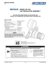
PARTS LIST 13-0041
Ind.
Ref. Replacement Parts
No. Part No. Description Req.
1 --- Cover 1
2 --- O-Ring 1
3 HAF-26 Baffle Kit 1
4 HAF-6 Filter and O-Ring Kit 1
*5 HAF-18 Automatic Drain 1
6 HAF-8 Plastic Bowl 1
7 HAF-19 Metal Bowl Guard 1
8 HAF-409 Clamp Ring 1
*9 --- 1/2 x 3/8 Vinyl Tubing 1
6 ft.
*10 HAF-11 Manual Drain 1
Figure 2 13-0041 (HAF-502) 100 CFM Water Separator Filter
1
2
4
6
*5 Automatic Drain
*10 Manual
Flexible Drain
7
8
*9 Used with automatic
drain only
3
EN
SB-6-156-R1 (3/2018)4 / 8www.carlisleft.com

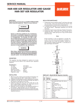
DESCRIPTION
The HAF-505, 55 CFM filter is designed to remove oil, dirt,
pipe scale and liquid aerosol. It includes a 0.01 micron filter
element and automatic mechanical drain.
PARTS LIST HAF-505
Ind.
Ref Replacement Description Parts
No. Part No. Req.
1 HAF-404 Filter Change Indicator 1
(not shown)
1A --- Cover 1
2 --- O-Ring 1
3 HAF-28 Filter and O-Ring Kit 1
4 HAF-18 Automatic Drain 1
5 HAF-8 Plastic Bowl 1
6 HAF-19 Metal Bowl Guard 1
7 HAF-409 Clamp Ring 1
*8 --- 1/2 x 3/8 Vinyl Tubing 6' 1
9 HAF-11 Manual Drain 1
(available separately)
Figure 3 HAF-505 55 CFM Oil Coalescing Filter
9 (Optional)
5
6
7
4
3
2
1A
1 (not shown)
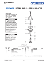
HAR-507 Regulator
DESCRIPTION
This regulator has been designed to receive
air at main line pressure and to deliver it at
a desired lower regulated pressure.
See WARNINGS on Page 3.
REGULATOR MAINTENANCE
1. Occasionally remove bottom plug (7)
and clean valve seat (11) and body.
Clean parts with denatured alcohol,
wipe off seat and blow out body with
compressed air.
2. To disassemble regulator, remove
screws, bonnett, spring and spring
button. Diaphragm assembly can now
be removed.
3. Check all o-rings for signs of damage.
Replace if necessary.
4. Reassemble parts. Center stem of valve
in hole of regulator body. Screw bottom
plug into body.
NOTE
Erratic operation or loss of regu-
lation is usually due to dirt in the
valve area and cleaning is neces-
sary. If cleaning does not correct
the problem, replace the items
included in Repair Kit KK-4977.
If unit leaks air at A , install Repair
Kit KK-4977.
Ind.
Ref
Replacement
Parts
No.
Part No.
Description Req.
1 --- #10-32 x 9/16 Fillister 6
Hd. Screw
2 HAR-14 Cover 1
3 --- Spring Button 1
4 --- Diaphragm Spring 1
5 --- Body 1
6 --- Pipe Plug 1/4" NPT(M) 1
7 --- Bottom Plug 1
8 KK-4977 Repair Kit (includes 1
Items 9 thru 14)
9 --- Diaphragm Assembly 1
10 --- O-Ring 1
11 --- Valve 1
12 --- O-Ring 1
13 --- Spring 1
14 --- O-Ring 1
PARTS LIST - Model HAR-507 Regulator
Assembly
Figure 4
HAR-507 Air Regulator
7
14
13
1
2
3
4
9
10
11
12
5
8
A
6
*8 Used with automatic
drain only
EN
SB-6-156-R1 (3/2018) 5 / 8 www.carlisleft.com

NOTE
The automatic drain includes a float. If water gets
into the float, the automatic drain may not function
properly. Under normal conditions, water will not enter
the float. However, water can get in the float if the filter
bowl is washed with the drain installed or if air line
contamination causes the drain mechanism to stick.
HAF-18 Automatic Drain
A Properly Piped Shop Of Prime Importance for a
Premium Finish.
The bottom line in finishing is a quality paint job. Though on the
surface it may not seem a significant factor in your being able to
turn out a quality paint job, the plumbing of your shop air lines
is very important. Correct installation is necessary for the proper
performance of your equipment - for an uncontaminated air
supply and for sufficient pressure to your spray gun.
Correct airline piping is so important that this one factor alone
can reduce contaminates in your air supply up to 75%*. Reduc-
ing contaminates to the filter also reduces the frequency of filter
replacement, maintenance, and of course, reduces the risk of
contaminates to the paint supply.
Even the size of the pipe is critical. Did you ever have only 60 or
70 pounds of pressure at your spray gun when your compressor
should deliver 100 pounds? Using pipe that is too small in diameter
can cause this pressure drop.
For example, if an air compressor delivers 100 psi through a 100 ft.
pipe, 1/2" in diameter, there’s greater pressure drop than if a 3/4"
diameter pipe were used.
The following chart will help reduce pipe pressure drop.
Minimum Pipe Size Recommendations
Compressor Compressor Main Min. Pipe
Size Capacity Air Line Diameter
1-1/2 and 2 HP 6 to 9 CFM Over 50 ft. 3/4"
3 and 5 HP 12 to 20 CFM Up to 200 ft. 3/4"
Over 200 ft. 1"
5 to 10 HP 20 to 40 CFM Up to 100 ft. 3/4"
100 to 200 ft. 1"
Over 200 ft. 1-1/4"
10 to 15 HP 40 to 60 CFM Up to 100 ft. 1"
100 to 200 ft. 1-1/4"
Over 200 ft. 1-1/2"
Body Shop Air Line Plumbing Guide:
After leaving the air compressor, air line pipe goes straight up
the shop wall as high as possible. This helps prevent any water
from leaving the compressor and traveling through the pipe.
Horizontal pipes should slope back towards the compressor at
least 4” per 50 ft. As warm air leaves the compressor, it cools
and thereby condenses as it travels through the pipe. This wa-
ter vapor, a problem in itself, also can cause scaling and rust
inside the piping. The backward sloping of the pipe helps push
these contaminates toward the compressor drain.
Take-off comes from the top of the main air supply line at each
air drop. This reduces the risk of water and other contaminates
from traveling down the drop into the water separator.
Pipe diameter must be of sufficient size for the volume of air
being passed as well as the length of pipe used. This will
minimize pressure drop.
First air drop should be at least 25 ft. from the compressor
although 50 ft. is optimum. This allows the compressed air to
cool to room temperature so any condensation can occur
before it gets to the water separator.
Shut-off valve is installed before the point of use filter. This
allows air to be shut off for filter maintenance.
Pipe union installed before DAD-500 allows easy installation
and removal of the air drying system.
Point-of use filter (not shown) attaches to spray gun, order
HAF-507. Strongly recommended for eliminating any remain-
ing contaminates.
Drain Valves - The daily draining of the system at each outlet
disposes of the contaminants that build up in the air supply.
Drain the compressor trap daily if equipped with a manual drain.
Proper maintenance of the air compressor can reduce airborne
contaminants such as particules and oils, and reduce heat and
|operating cost. Check air filters, oil level and perform regular
maintenance per operators manuals.
Guidelines To Piping Your Shop
• Pipe slopes upward - recommend 4” rise in 50 ft.
• Minimum 25 ft. to first outlet (50 ft. optimum)
• Pipe size (see chart)
• Shut off valve before filter
• Drain daily
1
2
3
4
5
6
8
9
10
7
You can confirm the automatic drain is not operating if the water
level in the plastic bowl is higher than the top of the automatic drain.
If the drain does not work properly, replace. It is not repairable.
2
10
4
3
6
5
9
9
7
8
1
EN
SB-6-156-R1 (3/2018)6 / 8www.carlisleft.com

NOTES
EN
SB-6-156-R1 (3/2018) 7 / 8 www.carlisleft.com

EN
SB-6-156-R1 (3/2018)8 / 8www.carlisleft.com
WARRANTY POLICY
This product is covered by Carlisle Fluid Technologies’ materials and workmanship limited warranty.
The use of any parts or accessories, from a source other than Carlisle Fluid Technologies,
will void all warranties. Failure to reasonably follow any maintenance guidance provided
may invalidate any warranty.
For specic warranty information please contact Carlisle Fluid Technologies.
For technical assistance or to locate an authorized distributor,
contact one of our international sales and customer support locations.
Region Industrial/Automotive Automotive Renishing
Americas
Tel: 1-800-992-4657 Tel: 1-800-445-3988
Fax: 1-888-246-5732 Fax: 1-800-445-6643
Europe, Africa,
Middle East, India
Tel: +44 (0)1202 571 111
Fax: +44 (0)1202 573 488
China
Tel: +8621-3373 0108
Fax: +8621-3373 0308
Japan
Tel: +81 45 785 6421
Fax: +81 45 785 6517
Australia
Tel: +61 (0) 2 8525 7555
Fax: +61 (0) 2 8525 7575
Carlisle Fluid Technologies is a global leader in innovative nishing technologies.
Carlisle Fluid Technologies reserves the right to modify equipment specications without prior notice.
DeVilbiss
®
, Ransburg
®
, ms
®
, BGK
®
, and Binks
®
are registered trademarks of Carlisle Fluid Technologies, Inc.
©2018 Carlisle Fluid Technologies, Inc.
All rights reserved.
For the latest information about our products, visit www.carlisleft.com
/