Moxa TCF-142-RM Series Quick Install Guide

Category
Network media converters
Type
Quick Install Guide

This manual is also suitable for

P/N: 1802001420642
*1802001420642*
TCF-142-RM Series
Quick Installation Guide
Version 6.0, February 2020
Technical Support Contact Information
www.moxa.com/support
Moxa Americas:
Toll
-free: 1-888-669-2872
Tel:
1-714-528-6777
Fax:
1-714-528-6778
Moxa China (Shanghai office):
Toll
-free: 800-820-5036
Tel:
+86-21-5258-9955
Fax:
+86-21-5258-5505
Moxa Europe:
Tel:
+49-89-3 70 03 99-0
Fax:
+49-89-3 70 03 99-99
Moxa Asia-Pacific:
Tel:
+886-2-8919-1230
Fax:
+886-2-8919-1231
Moxa India:
Tel:
+91-80-4172-9088
Fax:
+91-80-4132-1045
2020 Moxa Inc. All rights reserved.
- 2 -
Overview
Introduction
The TCF-142-RM series fiber converters are slide-in modules that can
be installed in the NRack System’s rackmount chassis, such as the TRC-
190 series. The slide-in module is equipped with a multiple interface
circuit that can handle RS-232 or RS-422/485 serial interfaces, and
multi-mode or single-mode fiber. The TCF-142-RM series slide-in
modules are used to extend serial transmission distance up to 5 km
(TCF-142-M-XX-RM, with multi-mode fiber) or up to 40 km (TCF-142-S-
XX-RM, with single-mode fiber).
Why Convert Serial to Fiber?
Fiber communication not only extends the communication distance, but
also provides many advantageous features. IMMUNITY FROM
ELECTRICAL INTERFERENCE: Fiber is not affected by electromagnetic
interference or radio frequency interference. It provides a clean
communication path and is immune to cross-talk. INSULATION: Optical
fiber is an insulator; the glass fiber eliminates the need for using
electric currents as the communication medium. SECURITY: Fiber
cannot be tapped by conventional electric means and is very difficult to
tap into optically. Furthermore, radio and satellite communication
signals can be captured easily for decoding. RELIABILITY &
MAINTENANCE: Fiber is immune to adverse temperature and moisture
conditions, does not corrode or lose its signal, and is not affected by
short circuits, power surges, or static electricity.
No Configuration Required for Baudrate Settings
The TCF-142-RM slide-in modules work under any baudrate from 50
bps to 921.6 Kbps. The TCF-142-RM slide-in modules simply convert
the signal back and forth between serial (RS-232, RS-422, or RS-485)
and fiber, and since the TCF-142-RM slide-in modules do not need to
interpret the signal, it does not need to know the baudrate of the
transmitting device. For this reason, the TCF-142-RM slide-in modules
do not have any DIP switches or jumpers for setting the baudrate.
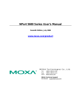
Ring Mode
To allow one half-duplex serial device to communicate with multiple
half-duplex devices connected to a fiber ring, you should configure the
TCF-142-RM slide-in modules for “ring mode” by setting DIP switch
“SW3” to the “On” position. The Tx port of a particular TCF-142-RM
slide-in modules unit connects to the neighboring converter’s Rx port to
form the ring. Note that when one node transmits a signal, the signal
travels around the ring until it returns to the transmitting unit, which
then blocks the signal. Users should ensure that the total fiber ring
length is less than 100 km when using either single-mode models or
multi-mode models.
- 3 -
Installation
The media converter slide-in module can be hot-swapped, which means
the chassis doesn’t have to power off or be removed during installation.
Align the slide-in module with the chassis installation slot so that the
panel fastener screw is at the top of the module. Carefully slide the
slide-in module into the slot while aligning the module’s circuit board
with the installation guide. Ensure the slide-in module is firmly seated
inside the chassis. Push in and rotate the attached panel fastener screw
clockwise to secure the module to the chassis.
Features
Ringor Point to Pointtransmission
Extend RS-232/422/485 transmission distance:
up to 40 km with single-modeTCF-142-S-XX-RM slide-in
modules series
up to 5 km with multi-modeTCF-142-M-XX-RM slide-in
modules series
Slide-in modules of NRack system
Decrease signal interference
Protect against electrical degradation and chemical corrosion
Support baudrate up to 921.6 Kbps
Package Checklist
Before installing the TCF-142-RM slide-in module, verify that the
package contains the following items:
TCF-142-RM slide-in module Fiber Converter
Quick Installation Guide
Warranty Card
NOTE: Please notify your sales representative if any of the above items
are missing or damaged.
- 4 -
Mounting Dimensions (Unit: mm)
TCF-142-SC
TCF-142-ST
- 5 -
ATTENTION
Electrostatic
Discharge Warning!
To protect the product from damage due to electrostatic
discharge, we recommend wearing a grounding device when
handling your TCF-142-RM-slide-in modules module series.
Pin Assignment and Connector
9-pin D-sub Female
RS-232
RS-422/485-4w
RS-485-2w
RxD-(A)
Data-(A)
TxD
RxD+(B)
Data+(B)
RxD
TxD+(B)
TxD-(A)
GND
GND
GND
Fiber Cable
SC-Port Pinouts
SC-Port to SC-Port Cable Wiring
ST-Port Pinouts
ST-Port to ST-Port Cable Wiring
ATTENTION
This is
a Class 1 Laser/LED product. Do not stare into the Laser
Beam.
- 6 -
Switch Settings
There are three sets of DIP switches on the board. One set for fiber and
another for the connector. Following are the settings for the three
connector DIP switches.
S1
Pin1 Pull High
Pin 2 Pull Low
Pin 3 Terminator
150 kilo-
ohms
OFF
ON
-
1 kilo-ohm
ON
OFF
-
120 ohms
(enable)
-
-
ON
120 ohms
(disable)
- - OFF
ATTENTION
For Fiber Ring Users:
Before you plug the slide
-
in module into the chassis, make sure
the DIP switch settings are correct before inserting the slide
-in
module into the chassis and connecting the serial and fiber
cables. If the Rx LEDs of the conv
erter glow continuously,
remove the fiber cable and reconnect.
NOTE
“Ring Mode” can only be used for half-duplex applications.
The settings for the RS-485 DIP switches are:
S1
Pin1
Pin 2
Pin 3
RS-232
ON
ON
-
RS-422
ON
OFF
-
RS-485 (4W)
OFF
OFF
-
RS-485 (2W)
OFF
ON
-
- 7 -
S1
Pin1
Pin 2
Pin 3
Ring
-
-
ON
Point to Point
-
-
OFF
The S3 DIP Switch is located inside the TCF-142-RM. When the TCF-
142-RM is in RS-485 mode, use this DIP switch to configure RS-485
data direction control, data format, and baudrate. When the TCF-142-
RM is in RS-232/422 mode, the S3 DIP switch cannot affect RS-
232/422 communication.
RS-485 Data Direction Control Settings
RS-485 Data Direction Control
S3 Pin 1
Auto Baudrate
OFF
Fixed Baudrate
ON
Data Format Settings
Data Format
S3 Pin 2
S3 Pin 3
S3 Pin 4
7 Bits
OFF
ON
ON
8 Bits
ON
OFF
ON
9 Bits
OFF
OFF
ON
10 Bits
ON
ON
OFF
11 Bits
OFF
ON
OFF
12 Bits
ON
OFF
OFF
The serial data format includes one start bit, between five and eight
data bits, and one stop bit. A parity bit and an additional stop bit might
be included in the format as well.
For example, 8-N-1 is interpreted as eight data bits, no parity bit, and
one stop bit. Users need to adjust the DIP switch to set the data format
to 10 bits.
Baudrate
S3 Pin 5
S3 Pin 6
S3 Pin 7
S3 Pin 8
S3 Pin 9
50
OFF
ON
ON
ON
ON
75
ON
OFF
ON
ON
ON
110
OFF
OFF
ON
ON
ON
134.5
ON
ON
OFF
ON
ON
150
OFF
ON
OFF
ON
ON
300
ON
OFF
OFF
ON
ON
600
OFF
OFF
OFF
ON
ON
1200
ON
ON
ON
OFF
ON
1800
OFF
ON
ON
OFF
ON
2400
ON
OFF
ON
OFF
ON
4800
OFF
OFF
ON
OFF
ON
7200
ON
ON
OFF
OFF
ON
9600
OFF
ON
OFF
OFF
ON
19200
ON
OFF
OFF
OFF
ON
38400
OFF
OFF
OFF
OFF
ON
57600
OFF
ON
ON
ON
OFF
115200
OFF
ON
ON
ON
OFF
230400
ON
OFF
ON
ON
OFF
460800
OFF
OFF
ON
ON
OFF
921600
ON
ON
OFF
ON
OFF
- 8 -
LED Indicators
There are three LEDs on the front bracket of the TCF-142-RM slide-in
modules.
LED
Color
Function
PWR
Green
Steady ON: Power is ON
Fiber Tx
Green
When sending serial data from the fiber port
Fiber Rx
Yellow
When receiving data from the fiber port
Specifications
Serial Communication
Signals for RS-232
TxD, RxD, SGND
Signals for RS-422
TxD+, TxD-, RxD+, RxD-, SGND
Signals for 4-wire RS-485
TxD+, TxD-, RxD+, RxD-, SGND
Signals for 2-wire RS-485
Data+, Data-, SGND
Baudrate
50 bps to 921.6 Kbps
ESD protection
15 KV ESD
Fiber Communication
Connector type
ST or SC
Distance
Single mode fiber for 40 km
Multi-mode fiber for 5 km
Support Cable
Single mode:
Multimode:
8.3/125, 8.7/125, 9/125 or 10/125 μm
50/125, 62.5/125, or 100/140 μm
Wavelength
Single mode: 1310 nm
Multimode: 850 nm
TX Output
Single mode: > -5 dBm
Multimode: > -5 dBm
RX Sensitivity
Single mode:
-25 dBm
Multimode: -20 dBm
Point-to-Point Transmission
Half or Full duplex
Multi-drop Transmission
Half duplex, fiber ring
Environmental
Operating Temperature
0 to 60°C (32 to 142°F), 5 to 95 % RH
Storage Temperature
-20 to 75°C (-4 to 185°F), 5 to 95 % RH
Power
Input Power Voltage
12 VDC
Power Consumption
150 mA @ 12V
Mechanical
Dimensions (W × D × H)
86.8 × 136.46 × 21 mm
Material
SPCC
Gross Weight
80 g
Regulatory Approvals
CE
Class A
FCC
Part 15 sub part B Class A
EMS
EN 61000-4-2 (ESD): Contact: 4 kV;
Air: 8 kV
EN 61000
-4-3 (RS): 80 MHz to 1 GHz:
3 V/m
EN 61000
-4-4 (EFT): Power: 1 kV;
EN 61000
-4-5 (Surge): Power: 2 kV (AC
Power); Power: 1 kV (DC Power).
EN 61000-4-6 (CS): 150 kHz to 80 MHz:
- 9 -
3 V/m
EN 61000
-4-8 (PFMF)
EN 61000-4-11 (DIPS)
Free fall
IEC 60068-2-32
  • Page 1 1
  • Page 2 2
  • Page 3 3
  • Page 4 4
  • Page 5 5
  • Page 6 6
  • Page 7 7
  • Page 8 8
  • Page 9 9

Moxa TCF-142-RM Series Quick Install Guide

Category
Network media converters
Type
Quick Install Guide
This manual is also suitable for

Ask a question and I''ll find the answer in the document

Finding information in a document is now easier with AI