Mountain Off-Road Heavy Duty Steering Box Relocation Mount Installation guide
- Type
- Installation guide

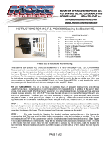
INSTRUCTIONS FOR M.O.R.E.™ SB7686-1 Steering Box Bracket H.D.
Please read Terms/Policies on page 2 before installing
PAGE 1 of 2
CONTENTS of KIT:
Qty: Description:
1 Bracket-Steering Box H.D.
3 Bracket to Box Spacers (3/4” thick)
1 Bracket to Box Spacer (1/4” thick)
1 Frame to Bracket Spacer (1/4” thick)
3 7/16” x 2” Bolts
4 7/16” x 1-1/2” Bolts
3 7/16” x 1” Bolts
10 7/16” Flat Washers
10 7/16” Lock Washers
Please read all instructions before installing.
This Steering Box Bracket H.D. (Heavy Duty) is designed to fit 1976-1986 Jeep® CJ-5, CJ-7, CJ-8 vehicles and
will move the steering gear forward 1 1/4”. Depending on the type of steering shaft your Jeep has , it may
be necessary to replace or modify the steering shaft ( see figure 7). Please read and understand all in-
structions before installing. Due to the fact that this bracket is over 300% stronger than the stamped steel fac-
tory bracket, the stress loads of large tires will be transferred directly to the frame. Because of the strength of
this bracket, your frame should be checked often for signs of cracking and stress. For this reason we recom-
mend using the optional third crossmember mounting hole. See STEP 2 for instructions on using this hole.
(Hardware has been provided in your kit for the use of this hole.) You may also consider Frame Plates
(#FP300), to help add more strength to the Jeep® CJ frame.
FIT and TOLERANCES: This kit is the result of countless hours of research, testing, fitting and refining.
Jeep® frames have a wide tolerance on bolt hole centers from frame to frame. In addition to the factory toler-
ances, most people install other then factory equipment (i.e.: steering gear boxes, bumpers, springs, winches,
shackle reversal systems, etc.) M.O.R.E.™ has done the best job we can to insure that this part fits with sev-
eral of the possibilities. However, you may find it necessary to modify (i.e.: grind, elongate, bend, or force)
the parts in this kit, or other parts on your Jeep®, to fit on your rig. Please use common sense when install-
ing these parts and understand that once you modify this part in any way, shape or form, it is not returnable.
STEP 1: Remove steering box and bracket from frame. It is not necessary to disconnect the steering
box from the pitman arm (or pitman arm from the drag link), or to disconnect the power steering hoses. Only
remove all bracket to frame bolts and, box to bracket bolts. Support the box with a floor jack or blocks. Be
careful not to damage the hoses! The old stamped steel brackets can now be discarded.
STEP 2: For extra strength the Steering Box Bracket has been designed to use a third bracket-to-
crossmember bolt. This hole must be drilled in the crossmember using the bracket as a template. To do this,
set the bracket on TOP of the crossmember with the third hole toward the driver side frame rail. (See Figure
4 for location of third hole in the bracket). Align the two existing holes and loosely thread two of the 7/16 bolts
in the bracket from the bottom. Now with the bracket held in position by the two bolts, mark the location for
the third hole. Remove the bracket, center-punch the location and drill with a ½" drill. Deburr the hole top and
bottom.
MOUNTAIN OFF ROAD ENTERPRISES LLC.
P O BOX 690 DELTA, COLORADO 81416
970-625-0500
E-MAIL: [email protected]
www.mountainoffroad.com

STEP 3: The steering shaft will need to be extended to reach the steering box after the box has been
moved forward. The shaft is telescoping from the factory (so it can collapse in case of a collision). To make it gain
length or extend the two halves must have the plastic locking device removed. The plastic must be melted out by
heating the shafts. If you choose this method, remove the entire shaft from the Jeep. Use a torch and slightly heat
the two halves until the plastic is melted out and the two shafts will slide apart. Do this in a well ventilated area
cause the melting plastic produces toxic fumes. Clean them with a wire brush, and paint them. Do not reinstall the
steering shaft at this time. ( SEE Note for Figure 7)
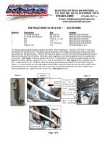
STEP 4: The inside lip on the crossmember will need to have a section removed to allow the steering box
to be moved forward.( see figure 1& 2). The brake line for the PS caliper is located behind this crossmember so
move it out of the way before you begin cutting. Be very careful that you do not damage the brake line or radiator
when cutting. After the crossmember has been cut we recommend cleaning the edges so there are no sharp
edges. We opted to weld in a piece of cold roll material to strengthen the crossmember after it had been cut. (see
figure 3 )
STEP 5 : Locate the ¼" bracket to box spacer, 1-½" bolt, flat washer and lock washer. Put the lockwasher,
and flat washer onto this bolt and insert through the hole on the bracket that is labeled #1 in (figure 5), with the
flat edge of the spacer facing the bracket. See figure 6 . (Note that the spacer goes on the opposite side of the
bracket from the washers). We recommend a dab of thread locking compound (Lock-Tight) be placed on all of the
mounting bolts. Now loosely thread the bolt into the hole of the steering box. Now all remaining box to bracket
bolts and spacers can be assembled in the same manner. Pay careful attention to assure that the flat side of the
spacers are facing the bracket. Once all four bolts are in, torque to approximately 45 ft/lbs.
STEP 6 : This step will be much easier with someone to assist in holding up the bracket while the bolts are
started. Lift assembly into position and align top two holes on the bracket with the existing holes in crossmember.
Loosely start both 1" bolts with flat and lock washers from the top. Tighten these bolts down to finger tight only
(these should not be tightened until all other bolts and spacers are in place.) Place remaining spacer (bracket to
frame) between frame and bracket aligned with the rearmost hole. Front two holes of bracket should be aligned
over the shackle mount (or Shackle Reversal System front pivot bracket). Insert 1-½" bolts using flat and lock
washers through all three holes and finger tighten. Tighten bolts through crossmember first and then bolts through
the frame. Torque bolts on crossmember to 45 ft/lbs. and bolts on frame to 35 ft/lbs. Reinstall the steering shaft.
Final Notes: Start vehicle and turn wheels lock to lock several times to check for any signs of binding or un-
usual noises. Torque on all bolts should be checked after the first few hours of use and then periodically after that.
Figure 1 Figure 2 Figure 3
PAGE 2 of 3

FIGURE 5 & 6
This picture shows
the H.D. Bracket
as it would be
installed in the
Jeep. The thin
spacer is placed
on the upper left
mounting bolt.
(#1).
FIGURE 4
This picture shows
the optional 3rd
mounting location
that you must drill
a hole in the
crossmember for.
#1
PAGE 3 of 3
FIGURE 7
The OEM Bell
type coupler may
need to be re-
placed with a
U-Joint type cou-
pler. This is only
necessary if you
run the sway bar
We recommend
Contacting
Borgeson.
TERMS/POLICIES:
RETURNS: No returns will be accepted without prior permission from M.O.R.E.™ LLC. You must call for a Return Goods Authorization (RGA)
number. Merchandise must be returned prepaid and insured. A claim must be made with in 30 days from receipt of merchandise. The original
invoice or a copy with the RGA number written on must accompany all returns. A 20% restocking fee will be charged on all parts returned for
credit or refund unless merchandise is proven to be defective or was shipped wrong by M.O.R.E.™ LLC. No merchandise will be issued credit
or refund if it has been installed, modified, used in any way or is in unsalable condition.
WARRANTY: All merchandise is warranted to be free from defects in materials and workmanship prior to installation. Any alteration or im-
proper use will void this warranty. Because all parts we sell are intended for use in heavy-duty applications it is not possible to warrantee or
guarantee the performance of any items. M.O.R.E.™ LLC. products and the products manufactured by others, which we sell may be subject
to an infinite variety of conditions due to the manner in which they are used, serviced and/or installed. Purchasers and users of such products
rely upon their own judgment as to the suitable use selection, service and installation of such products.
PRODUCT DISCLAIMER: Modification of your vehicle to enhance performance with parts sold by M.O.R.E.™ LLC. may create a dangerous
condition which could cause serious bodily injury, and the buyer hereby expressly assumes all risks associated with any such modifications.
All parts sold by M.O.R.E.™ LLC. are for racing or off road use only. Mountain Off Road Enterprises LLC. will not accept responsibility for
personal injury or property damage arising from the failure of any parts manufactured or sold by M.O.R.E.™ LLC.
Specifications are subject to change without notice.
These instructions, and the M.O.R.E.™ logo are copyright©, 2000-2008.
-
 1
1
-
 2
2
-
 3
3
Mountain Off-Road Heavy Duty Steering Box Relocation Mount Installation guide
- Type
- Installation guide
Ask a question and I''ll find the answer in the document
Finding information in a document is now easier with AI
Related papers
-
 Mountain Off-Road Heavy Duty Steering Box Mount Installation guide
-
 Mountain Off-Road 1" Steering Shaft Riser Bracket Installation guide
-
 Mountain Off-Road Hide-A-Step Installation guide
-
 Mountain Off-Road Standard Shackle Reversal Kit Installation guide
-
 Mountain Off-Road Standard Shackle Reversal Kit Installation guide
-
 Mountain Off-Road JKEVSP12 Installation guide
-
 Mountain Off-Road DP0709PS MORE Installation guide
-
 Mountain Off-Road JKESP07 Installation guide
-
M.O.R.E. BLTJ97 MORE Installation guide
-
 Mountain Off-Road TJOPSP03 Installation guide
Other documents
-
 Zone Offroad Products 4.5" Lift Kit Installation guide
-
ReadyLIFT 6'' Lift Kit 2019-2023 Ram 2500 Operating instructions
-
Rubicon Express RE7530 Installation guide
-
Rubicon Express JK4443 Installation guide
-
Rubicon Express RE7515M Installation guide
-
Rubicon Express RE7232 Installation guide
-
 Zone Offroad Products 4" Lift Kit Installation guide
-
 Fishbone Offroad FB26318 Installation guide
-
 Superlift 4" Lift Kit Installation guide
-
ReadyLIFT 6" SST Lift Kit - 2022-2023 Toyota Tundra Rear Air 2WD/4WD Operating instructions


