Page is loading ...

The GPI HP-100 DUAL-FLO® Petroleum Hand Pump
is designed to manually pump petroleum products
compatible with aluminum and Buna-N. The user has
the exibility of operating the pump at two owrates. A
setting of 1/2-gallon provides faster high-capacity ow.
A 1/4-gallon setting allows for easier pumping of uids.
The HP-100 Hand Pump is designed for use on a tank
with a 2-inch bung.
Read Me!
Observe standard precautions when handling fuel.
• Keep fuel away from open ame or spark.
• Do not refuel vehicles or equipment with engines
running or while equipment engine is hot.
• Do not smoke while refueling.
Rev. C 921407-10
1
06/12
5252 East 36th Street North
Wichita, KS USA 67220-3205
TEL: 316-686-7361
FAX: 316-686-6746
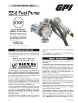
HP-100 Dual-Flo®
Petroleum Hand Pump
Owner’s Manual
STOP
DO NOT RETURN
THIS PRODUCT
TO THE STORE!
Please contact GPI before
returning any product. If you
are missing parts or experience
problems with your installation,
our Customer Support Depart-
ment will be happy to assist you.
GPI Customer Support
800-835-0113 or
316-686-7361
TABLE OF CONTENTS
General Information ....................................................1
Installation .................................................................. 2
Operation and Maintenance .......................................3
Troubleshooting ..........................................................4
Illustrated Parts List ....................................................5
Specications ............................................................. 6
Parts and Service .......................................................6
GENERAL INFORMATION

Use the following procedures to install the HP-100 Hand
Pump on a tank with a 2-inch bung.
Install Suction Pipe
1. Remove the two protective plugs from the pump
inlet and outlet ports.
2. Wrap the threaded end of the suction pipe with 3 to
4 turns of thread tape.
3. Insert the suction screen into the inlet cover.
4. Place the spacer in the inlet cover to secure the inlet
screen.
5. Install the suction pipe into the inlet cover and tighten
rmly with a pipe wrench.
Install Pump on Tank
1. Before installing the pump, clean the tank interior
of all dirt and foreign material.
2. Lubricate the threads of the inlet cover with thread
tape or a thread-sealing compound approved for
use with petroleum fuels.
3. Extend the adjustable suction pipe to its full length
and carefully insert it into tank opening. The suction
pipe will adjust to the length needed and rest on the
bottom of tank.
NOTE: The suction pipe supplied has a variable length
of 22 to 40 inches. If additional length is needed,
order the 15-inch Suction Pipe Extension Kit.
4. Thread the inlet tting of the pump onto the tank
and turn the pump to tighten snugly.
NOTE: To prevent the buildup of pressure and possible
fuel leakage through the nozzle, make sure the
tank is vented.
Install Hose & Nozzle Assembly
Apply 3 to 4 wraps of thread tape to the threaded end of
the hose and hand-tighten into the outlet cover until snug.
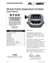
Install Handle
The HP-100 Hand Pump gives the operator a choice of
two ow settings:
• 1/4-gallon setting has low resistance and pumps 1/4
gallon per stroke cycle.
• 1/2-gallon setting has higher resistance and pumps
1/2 gallon per stroke cycle.
Figure 3
1/2-gallon setting
shown here
➤
Volume per stroke is determined by connecting the piston
shaft to the appropriate handle setting as outlined below.
NOTE: Clevis pins may be installed from either side of
handle.
1. Slide the handle grip onto the pump handle.
2. To install the links on the pump, insert a long clevis
pin through the link ends and the pump’s link holes.
Secure with a small cotter pin. (Figure 1)
2
Figure 1
Figure 2
Attach links to first hole
Use for 1/2-gallon setting
Use for 1/4-gallon setting
➤
➤
➤
4. Insert a screwdriver in the piston shaft of the pump
and pull the piston out. Install the shaft on the handle
at either piston hole by placing a short clevis pin
through the handle and the piston shaft end and
securing with the hitch clip pin.
NOTE: Select the upper piston hole on the handle for the
1/2-gallon setting (Figure 3) or the lower piston hole for
the 1/4-gallon setting. Flow settings can be changed at
any time by repositioning the piston shaft on the handle.
INSTALLATION
Use the HP-100 Hand Pump only with diesel fuel
(biodiesel blends B20), gasoline (alcohol blends E15),
hydraulic uid, kerosene and oil (up to 30 wt.). This
equipment should not be used to pump chemicals.
3. Attach the free ends of the links to the bottom, outer
surfaces of the handle. Insert a long clevis pin through
the holes on both links and the lowest hole on the
handle. Secure with a small cotter pin. (Figure 2)

3
Figure 4
To Dispense Fluid
1. Remove the nozzle from its holder and insert into
the receiving tank of the equipment or vehicle.
2. Choose a handle setting for the desired owrate:
• 1/4-gallon setting for low-volume, low-resistance
pumping
• 1/2-gallon setting for high-volume, high-resistance
pumping
3. To operate pump, manually move the handle in a
push/pull motion.
4. After dispensing the desired amount of uid, drain
the hose and nozzle. Place the nozzle in its holder
and return the handle to its upright storage position.
During daily use, the GPI HP-100 Hand Pump is es-
sentially maintenance free. However, the pump should
be inspected periodically for signs of leakage. If leaks
are present, make appropriate repairs. Refer to the
Troubleshooting section.
NOTE: Lock the handle to the pump by pushing the
handle against the pump and inserting a padlock
through either of the top holes in the handle and
through the pump’s lock hole. (Figure 4)
OPERATION & MAINTENANCE

SYMPTOM PROBABLE CAUSE CORRECTIVE ACTION
A. FLUID LEAKS 1. Packing seals settled Tighten two screws on the retainer and torque to approximately
AROUND SHAFT 20 lb. in. (or hand tighten then another half turn until leak stops)
SEAL
2. Seals worn Remove the two screws on the retainer and remove the retainer
and bearing. Remove all three seals and replace.
B. FLUID LEAKS AT 1. Anti-siphon valve or Replace vent plug assembly. Remove the black cap. Remove old
ANTI-SIPHON VALVE O-ring damaged vent plug assembly by turning counterclockwise. Install new vent
plug assembly. Replace cap.
C. LOW FLOWRATE 1. Inlet screen clogged Remove the pump from the tank. Remove the suction pipe, spacer,
and inlet screen from the bottom of the pump. Clean the inlet
screen and assemble. Place the pump on the tank using installa-
tion instructions.
2. Suction pipe leak Remove the pump from the tank. Inspect the spacer and suction
pipe to ensure they are not worn or damaged. Replace as neces-
sary and install the suction pipe and pump again using installation
instructions.
3. Piston ring or liner Remove the piston cover and inspect the piston ring and liner.
worn Scoring and severe scufng on the liner indicates wear. If neces-
sary, install an Overhaul Kit.
4. Piston cracked Remove the piston cover and inspect the piston. Install an
Overhaul Kit, if necessary.
D. PUMP SEIZED 1. Debris in piston or liner Disassemble and clean the piston and liner. Check for debris
lodged in the piston ring or behind the liner. Small dimples in the
liner indicate dirt, debris or welding slag contaminants in the tank.
Replace the piston ring and liner. If appropriate, ush the tank of all
contaminants.
4
TROUBLESHOOTING

A
A
A
Kits and Accessories
114510-3 Hardware Kit includes handle grip, links, pins and
screen.
114505-2 Overhaul Kit includes piston ring, three seals, pack-
ing seals and liner.
114509-1 Inlet Cover Kit includes inlet cover, spacer and
screen.
115527-2 Suction Pipe Extension, 15 inches.
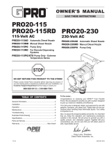
Item No.n
No. Part No. Description Req’d.
2 114014-2 Handle .............................................. 1
8 904004-30 Screw, hex head, 10-32 x 5/8 in. ...... 2
9 114017-2 Retainer ............................................ 1
10 114016-1 Bearing ............................................. 1
13 114034-1 Packing Seal or (Kit ) .................. 3
14 114042-1 Body ................................................. 1
15 114009-1 Spring ............................................... 4
16 114007-1 Plate ................................................. 2
17 114008-1 Valve ................................................ 4
18 114043-4 Outlet Cover, 3/4 in. ......................... 1
19 904002-23 Screw, Sems, 1/4-20 x 3/4 in. ........ 14
20 114006-1 Seal or (Kit ) ................................ 2
21 123504-1 Anti Siphon Vent Kit ......................... 1
23 114041-1 Piston Cover ..................................... 1
24 901001-51 Cover Seal or (Kit ) ...................... 1
25 906005-58 Piston Ring or (Kit ) ..................... 1
26 114021-02 Piston Assembly ............................... 1
27 114011-1 Liner or (Kit ) ............................... 1
32 114509-1 Inlet Cover Kit (Kit ) ..................... 1
34 114037-1 Inlet Screen or (Kit ) .................... 1
35 114038-1 Spacer or (Kit ) ............................ 1
36 110100-1 Adjustable Suction Pipe, 22-40 in. ... 1
37 114504-3 Hose and Nozzle Assembly
Kit (Non-UL model) ...................... 1
A
B
C
B
B
B
B
C
C
C
B
5
ILLUSTRATED PARTS LIST

6
The HP-100 Dual-Flo® Petroleum Hand Pump is
compatible with a wide variety of petroleum products and
ts any container with a 2-inch NPT bung. Use with diesel
fuel (biodiesel blends B20), gasoline (alcohol blends
E15), hydraulic uid, kerosene and oil (up to 30 wt.).
This equipment should not be used to pump chemicals.
Construction: Lightweight, die-cast aluminum
housing. Stainless steel piston
shaft and liner. Buna-N seals.
Built-in air valve to prevent
leakage at the nozzle.
Pumping Capacity: 1/2 gallon (1.9 litres) per stroke
cycle.
Pumping Settings: 1/2-gallon setting for high
volume, high resistance.
1/4 gallon setting for low volume,
low resistance.
Inlet: Standard 1-inch NPT pipe.
Outlet: Standard 3/4-inch NPT pipe.
Shipping Weight: 14 lbs.
Hose and Nozzle: Non-UL Model:
3/4 inch x 8 foot Buna-N hose.
Thermoplastic unleaded nozzle.
Built-in nozzle holder.
UL Model:
3/4 inch x 8 foot Electrically
Conductive hose (UL Listed)
with metal nozzle.
Suction Pipe: Plastic, adjustable 22 to 40 inches.
For warranty consideration, parts or other service
information, please contact your local distributor or the
GPI Customer Service Department in Wichita, Kansas,
during normal business hours.
1-800-835-0113
To obtain prompt, efcient service, be prepared with the
following information:
• The model number of your pump.
• The manufacturing date of your pump.
• Part descriptions and numbers.
Part descriptions and numbers can be obtained from
the Illustrated Parts List.
For warranty service, be prepared with your original
sales slip or other evidence of purchase date.
SPECIFICATIONS PARTS AND SERVICE


Dual-Flo and GPI are registered trademarks of
Great Plains Industries, Inc.
© 2012 by GREAT PLAINS INDUSTRIES, INC., Wichita, KS
Printed in U.S.A.
5252 East 36th Street North
Wichita, KS USA 67220-3205
TEL: 316-686-7361
FAX: 316-686-6746
Rev. C 921407-1006/12
Limited Warranty Policy
Great Plains Industries, Inc. 5252 E. 36th Street North, Wichita, KS USA 67220-3205, hereby provides a limited warranty against
defects in material and workmanship on all products manufactured by Great Plains Industries, Inc. This product includes a 2 year
warranty from date of purchase as evidenced by the original sales receipt. A 30 month warranty from product date of manufacture
will apply in cases where the original sales receipt is not available. Reference product labeling for the warranty expiration date
based on 30 months from date of manufacture. Manufacturer’s sole obligation under the foregoing warranties will be limited to
either, at Manufacturer’s option, replacing or repairing defective Goods (subject to limitations hereinafter provided) or refunding
the purchase price for such Goods theretofore paid by the Buyer, and Buyer’s exclusive remedy for breach of any such warranties
will be enforcement of such obligations of Manufacturer. The warranty shall extend to the purchaser of this product and to any
person to whom such product is transferred during the warranty period.
This warranty shall not apply if:
A. the product has been altered or modied outside the warrantor’s duly appointed representative;
B. the product has been subjected to neglect, misuse, abuse or damage or has been installed or operated other than in
accordance with the manufacturer’s operating instructions.
To make a claim against this warranty, contact the GPI Customer Service Department at 316-686-7361 or 800-835-0113. Or by
mail at:
Great Plains Industries, Inc.
5252 E. 36th St. North
Wichita, KS, USA 67220-3205
GPI will step you through a product troubleshooting process to determine appropriate corrective actions.
GREAT PLAINS INDUSTRIES, INC., EXCLUDES LIABILITY UNDER THIS WARRANTY FOR DIRECT, INDIRECT, INCIDENTAL
AND CONSEQUENTIAL DAMAGES INCURRED IN THE USE OR LOSS OF USE OF THE PRODUCT WARRANTED HEREUNDER.
The company herewith expressly disclaims any warranty of merchantability or tness for any particular purpose other than for
which it was designed.
This warranty gives you specic rights and you may also have other rights which vary from U.S. state to U.S. state.
Note: In compliance with MAGNUSON MOSS CONSUMER WARRANTY ACT – Part 702 (governs the resale availability of the
warranty terms).
/