Page is loading ...

922029-01 Rev E03/18
To the owner...
Congratulations on receiving your GPI
®
oil pump. We are
pleased to provide you with a system designed to give
you maximum reliability and efciency.
Your pump is designed for use with motor oil, gear oil,
hydraulic oil and waste oil. If used with antifreeze, do not
exceed 50% water. Please take all due precautions when
handling these liquids. Your safety is important to us.
Also, to assure the longest possible service life, it is im-
portant that you follow the operation and maintenance
procedures outlined in this manual. We are proud to
provide you with a quality product and dedicated sup-
port. Together with your conscientious use, we are sure
that you will obtain years of safe, dependable service.
Victor Lukic, President
Great Plains Industries, Inc.
Oil Pump
Models L 5016, L 5116 & L 5132
Owner’s Manual
TABLE OF CONTENTS
General Information .................................................... 2
Safety Instructions ...................................................... 2
Installation .................................................................. 2
Operation .................................................................... 3
Maintenance ............................................................... 3
Troubleshooting .......................................................... 4
Viscosity Charts .......................................................... 5
Illustrated Parts List .................................................... 6
Specications ............................................................. 7
Service........................................................................ 7
Warranty ..................................................................... 8
DO NOT RETURN THIS
PRODUCT TO THE STORE!
Please contact GPI before returning
any product. If you are missing
parts or experience problems with
your installation, our Customer
Support Department will be
happy
to assist you:
800-835-0113 or
316-686-7361
SAVE THIS OWNER’S MANUAL

2
GENERAL INFORMATION
The purpose of this manual is to assist you in installing,
operating and maintaining your GPI Oil Pump. This pump
is a positive displacement, direct drive pump.
Models L 5116 and L 5132 are wired for 115-volts only,
however these motors have the capability to run on
230-volts if properly wired by an Electrician (see the label
on the motor for specications). GPI does not supply any
wiring items or hookup connectors for the 230 voltage.
Rewiring for 230-volts is the risk and responsibility of the
buyer/owner and user. GPI is not liable for any damage
or accidents caused by rewiring.
Both the 12-volt DC and the 115-/230-volt AC pump are
compatible with motor oil, gear oil, hydraulic oil, antifreeze
(not to exceed 50% water), ATF and waste oil. Do not
use this pump for dispensing any uids other than those
for which it was designed. To do so may damage pump
components and will void the warranty.
Do not use the GPI Oil pump with water, acids, brake
uid or windshield washer uid.
If in doubt about compatibility of a specic uid, contact
the supplier of the uid to check for chemical compat-
ibility with:
• Aluminum • Stainless Steel
• Brass • Steel
• Nitrile Rubber • Zinc Plated Steel
Do not leave the system running without uids. “Dry run-
ning” can damage the pump.
Do not pump the tank completely dry, as contaminants
from the bottom of the tank may enter the pump.
SAFETY INFORMATION
The following safety alert symbols are used in
this manual.
DANGER
DANGER indicates an
imminently hazardous
situation which, if not
avoided, will result in death
or serious injury.
WARNING
WARNING indicates
a potentially hazardous
situation which, if not
avoided, could result in
death or serious injury.
CAUTION
CAUTION indicates
a potentially hazardous
situation which, if not avoid-
ed, may result in minor or
moderate injury.
It is your responsibility to:
• know and follow applicable national, state and local
safety codes pertaining to installing and operating
electrical equipment for use with petroleum uids.
• ensure that all equipment operators have access to
adequate instructions concerning safe operating and
maintenance procedures.
Observe all safety precautions concerning safe handling
of petroleum uids. Do not use pump with low ash point
uids (100° F or less).
To ensure safe operation, this pump must be properly
grounded. Care should be taken to ensure proper ground-
ing during initial installation and after any service or repair
procedures. For your safety, please take a moment to
review the warnings below.
Observe precautions against electrical shock when oper-
ating the system. Serious or fatal shock can result from
operating electrical equipment in damp or wet locations.
On 12-volt pumps, inspect external pump wiring regularly
to make sure it is correctly attached to the battery. To
avoid electrical shock, use extra care when connecting
the pump to power.
GPI recommends installing only one pump per
battery. Using more than one pump on the same
battery could create a hazardous situation in a
fault condition. As an option, use an appropriate
selector switch that allows only one pump to be
run at a time.
WARNING
Avoid prolonged skin contact with petroleum uids. Use
protective goggles, gloves and aprons in case of splash-
ing or spills. Change saturated clothing and wash skin
promptly with soap and water.
Observe precautions against electrical shock when
servicing the pump. Always disconnect power before
repairing or servicing. Never apply electrical power to
the system when any of the coverplates are removed.
If using solvent to clean pump components or tank, ob-
serve the solvent manufacturer’s recommendations for
safe use and disposal.
The 115-/230-volt AC pump motors are equipped with
thermal overload protection. If overheated, the pump will
shut itself off. Turn off the pump if this occurs. See Motor
Protector Section for details.
Worn and damaged hoses or nozzles are potential safety
hazards and should be replaced.
INSTALLATION
Make sure all threaded connections are wrapped with
three to four turns of oil resistant thread tape or pipe
thread sealant.
Make sure drums are properly secured to prevent tip over
when full or empty. All tanks must be properly vented.

3
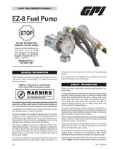
Installing Pump to a Tank
GPI pumps have a 2-inch NPT connection that can be
mounted directly to a 2-inch female pipe thread on the tank.
1. Clean the tank interior of all dirt and foreign material.
2. Glue sections of suction pipe together and cut it to
the proper length that is required. Suction pipe should
extend 2 to 3 inches above bottom of tank.
3. Screw suction pipe into inlet threads of pump base.
4. Insert the suction pipe through the tank bung. Screw
pump into tank bung to secure the pump to the tank.
(Figure 1)
FIGURE 1
GPI
®
5. To prevent pressure buildup and possible leaks through
the ball valve, make sure the tank is vented.
Installing Discharge Plumbing on
Pump Outlet
1. Install a 90 degree elbow to the pump outlet using oil
resistant pipe sealant.
2. Install the hose and ball valve using oil resistant pipe
sealant on the threads. Tighten securely.
Electrical Installation
Electrical wiring must be done by a licensed electrician. Shut
off all power before connecting wires to motor. Failure to follow
these wiring instructions may result in death or serious injury from
shock, re or explosion.
WARNING
115-/230-volt AC Powered Pumps
(Models L 5116 & L 5132):
This GPI Oil Pump is factory wired for 115-volt AC. These
motors have the capability to run on 230-volts if properly
wired by an electrician. Power to the unit should be sup-
plied from a dedicated circuit breaker.
If AC extension cords are used, they must be capable of
safely carrying the rated motor current. Use only heavy
duty, 3-wire, grounded extension cords.
NOTE: Many building codes require Ground Fault Circuit
interrupt (GFCI) protection.
Motor Ratings (FLA):
115-/230-volt AC:
1/2 HP, 1725 RPM – 7.5/3.7 amps
1 HP, 3450 RPM – 13.3/6.6 amps
12-volt DC:
1/2 HP, 1800 RPM – 40 amps
12-volt DC Powered Pumps (Model L 5016):
This GPI Oil Pump is factory wired for 12-volt DC. Circuit
must be protected with a 50 amp automotive-type fuse
(not supplied).
The power cord is not supplied with the pump. GPI rec-
ommends a minimum power cord of 10/3 AWG. Do not
exceed 15 feet of cord.
OPERATION
Do not operate pump dry. Damage to pump could occur.
CAUTION
Before rst usage, pour oil into pump outlet port to coat
pumping element.
1. Place ball valve into the receiving tank to be lled.
2. Turn on the motor.
3. Open the ball valve and ll the container to the desired
level. If ow does not occur within 15 seconds, shut
off motor and refer to the priming information in the
Troubleshooting Section.
4. Shut off the nozzle.
5. Turn off the motor.
Motor Protector
The AC pumps contain thermal motor protection. If the
pump overheats the unit will shutoff.
If the motor shuts off, follow these instructions:
Model L 5132: Turn off the switch. Allow the motor to
cool before restarting.
Model L 5116: Turn off the switch. Allow the motor to cool.
Push the button to manually reset the protector.
Model L 5016: The 12-volt model should be protected by
an inline fuse (not supplied). If the motor shuts
off, check the fuse.
MAINTENANCE
Disconnect power and relieve pressure in the system by
opening the nozzle before servicing the pump.
This pump is designed for minimum maintenance. Motor
bearings are sealed and require no lubrication. Inspect
the pump and components regularly for leaks and make
sure the hose, ball valve and components are in good
condition.
Use of the pump with unauthorized uids will void the
warranty.
Remove and clean the strainer if low ow is noticed.
To clean the strainer, remove the three screws on the
strainer cover. Remove cover and pull out screen. Clean
screen and reinstall. Care should be taken not to dam-
age the O-ring.

4
TROUBLESHOOTING
SYMPTOM PROBABLE CAUSE CORRECTIVE ACTION
A. PUMP WON’T
PRIME
1. Dirty strainer screen Remove and clean strainer.
2. Suction line problem Check for leaks in suction line.
3. Pump outlet is blocked or valve is
shutoff
Check pump outlet system for blockage.
4. Fluid level below suction pipe Rell tank or add longer suction pipe.
5. Fluid viscosity exceeds pumps
rated capability
Refer to the Viscosity Charts for viscosity limits.
6. Gerotor is locked Inspect gerotor for smooth rotation. Remove any debris.
7. Excessive gerotor wear Inspect gerotor. Replace if worn.
8. Bypass valve not seating Remove / inspect bypass valve. Clean if necessary.
B. LOW FLOWRATE
1. Dirty strainer screen Remove and clean strainer.
2. Suction line problem Check for leaks in suction line.
3. Fluid viscosity exceeds pumps
rated capability
Refer to the Viscosity Charts for viscosity limits.
4. Nozzle or meter pressure
exceeds product specications
Replace meter or nozzle.
5. Bypass valve not seating Remove / inspect bypass valve. Clean if necessary.
6. Excessive gerotor wear Inspect gerotor. Replace if worn.
7. Low voltage to motor Ensure power at motor is at proper voltage.
8. Motor wired for incorrect voltage Rewire for correct voltage. Instructions are on motor nameplate.
C. MOTOR STALLS
WHEN VALVE/
NOZZLE IS
CLOSED
1. Bypass valve is sticking Remove / inspect bypass valve. Clean if necessary.
D. MOTOR STALLS
WHEN PUMP
FIRST STARTS
1. Fluid viscosity exceeds pumps
rated capability
Refer to the Viscosity Charts for viscosity limits.
2. Gerotor is locked Inspect gerotor for smooth rotation. Remove any debris.
E. MOTOR
OVERHEATS
1. Fluid viscosity exceeds pumps
rated capability
Refer to the Viscosity Charts for viscosity limits.
2. Gerotor is not rotating smoothly Inspect gerotor for smooth rotation. Remove any debris.
3. Incorrect voltage Ensure power at motor is at proper voltage.
F. MOTOR WILL
NOT TURN ON
1. No power to motor Check circuit breakers and electrical connections.
2. Switch failure Replace switch.
3. Motor has tripped internal motor
protection
Allow motor to cool for at least 30 minutes.
G. PUMPS LEAK
1. Missing or damaged seals Inspect affected areas for proper O-ring sealing.
2. Shaft seal damage Inspect and replace shaft seal if needed.
3. Incompatible uid pumped Check if uid is compatible with aluminum, brass, nitrile rubber, stain-
less steel, steel and zinc plated steel.

5
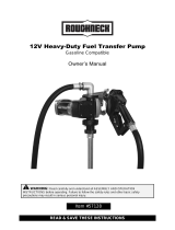
VISCOSITY CHARTS

6
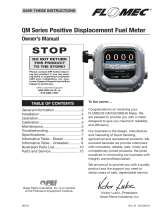
Item No.
No. Part No. Description Req’d.
1 110264-1 Suction Pipe Assembly ...................................... 1
2 110264-2 Suction Pipe Assembly ...................................... 1
3 110187-509 Hose Assembly .................................................. 1
4 142001-01 Gerotor Housing Adapter ................................... 1
5 142002-01 Pump Body ........................................................ 1
6 142021-01 Poppet Assembly ............................................... 1
7 142500-01 Gerotor Kit (Element & O-Ring) ......................... 1
8 142005-01 Bypass Spring .................................................... 1
9 142008-01 Inlet Screen ........................................................ 1
10 142009-01 Base Cover ........................................................ 1
11 142014-01 Motor, 115-/230-volt AC, 1/2 HP, 1725 RPM ...... 1
12 142015-01 Motor, 115-/230-volt AC, 1 HP, 3450 RPM ......... 1
13 142016-01 Motor, 12-volt DC, 1/2 HP, 1800 RPM ................ 1
14 142022-01 Inlet Base Assembly .......................................... 1
15 142023-01 Poppet Plug Assembly ....................................... 1
16 90100389 O-Ring ................................................................ 1
17 90100387 O-Ring, Nitrile..................................................... 1
18 90100388 O-Ring, Nitrile..................................................... 1
19 904002-24 Sems Screw & Washer Assembly ...................... 4
20 904005-59 Spring Pin .......................................................... 2
21 90400807 Sems Hex Head, 3/8"-16 x 3/4" ......................... 4
22 90400793 Hex Head Screw, 5/16"-18 x 1-3/4".................... 4
23 90400794 Sems Hex Head, 1/4"-20 x 1/2" ......................... 3
24 90400795 Radial Lip Seal ................................................... 1
25 90600658 Ball Valve with 45° Spout ................................... 1
ILLUSTRATED PARTS LIST
GPI
®

7
For warranty work, always be prepared with your original
sales slip or other evidence of purchase date.
Please contact GPI before returning any pump. It may
be possible to diagnose the trouble and nd a solution
with a telephone call. GPI can also inform you of any
special requirements you will need to follow for shipping.
Do not return the pump without authority from the Customer
Service Department. Due to strict government regulations, GPI
cannot accept pumps unless they have been drained and cleaned.
CAUTION
SERVICE
For warranty consideration, parts, or other service infor-
mation, please contact your local distributor. If you need
further assistance, contact the GPI Customer Service
Department in Wichita, Kansas, during normal business
hours. A toll free number is provided for your convenience.
1-800-835-0113
To obtain prompt, efcient service, always be prepared
with the following information:
1. The model number of your pump.
2. The manufacturing date code of your pump.
SPECIFICATIONS
SAVE THESE INSTRUCTIONS
Model:
L 5016
12-volt DC Pump
L 5116
115-volt AC 1/2 HP
L 5132
115-volt AC 1 HP
Pump Housing: Aluminum Aluminum Aluminum
Performance:
Pump Rate: 16 QPM (15 LPM) 16 QPM (15 LPM) 32 QPM (30 LPM)
Duty Cycle: 30 min. ON, 30 min. OFF 30 min. ON, 30 min. OFF 30 min. ON, 30 min. OFF
Max. Viscosity Pumped: 390 CPS 1160 CPS 970 CPS
Operating Temperature: Maximum temperature is +140° F (+60° C). See Viscosity Chart for minimum temperature.
Operating Pressure: 50 PSI
Electrical Specications:
Input: 12-volt DC 115-/230-volt AC 115-/230-volt AC
Current Draw: 40 amps 7.5/ 3.7 amps 13.3/ 6.6 amps
Motor: 1800 RPM 1725 RPM 3450 RPM
Motor Approval:
UL Recognized Component,
CSA Certied
UL Recognized Component,
CSA Certied
UL Recognized Component,
CSA Certied
Motor Protection: Inline Fuse (not supplied) Thermal Protection Thermal Protection
Cord:
Min. 10/3 x 15 ft.
(not supplied)
36 in. with Grounded
NEMA Plug
36 in. with Grounded
NEMA Plug
Mechanical Connections:
Bung: 2-inch NPT 2-inch NPT 2-inch NPT
Inlet: 1-inch NPT 1-inch NPT 1-inch NPT
Outlet: 3/4-inch NPT 3/4-inch NPT 3/4-inch NPT
Weight: 43.4 lbs. 33.7 lbs. 43.6 lbs

UL Recognized
Component
Limited Warranty Policy
Great Plains Industries, Inc. 5252 E. 36
th
Street North, Wichita, KS USA 67220-3205, hereby provides a limited warranty against
defects in material and workmanship on all products manufactured by Great Plains Industries, Inc. This product includes a 1 year
warranty from date of purchase as evidenced by the original sales receipt. A 30 month warranty from product date of manufacture
will apply in cases where the original sales receipt is not available. Reference product labeling for the warranty expiration date based
on 30 months from date of manufacture. Manufacturer’s sole obligation under the foregoing warranties will be limited to either, at
Manufacturer’s option, replacing or repairing defective Goods (subject to limitations hereinafter provided) or refunding the purchase
price for such Goods theretofore paid by the Buyer, and Buyer’s exclusive remedy for breach of any such warranties will be enforce-
ment of such obligations of Manufacturer. The warranty shall extend to the purchaser of this product and to any person to whom
such product is transferred during the warranty period.
This warranty shall not apply if:
A. the product has been altered or modied outside the warrantor’s duly appointed representative;
B. the product has been subjected to neglect, misuse, abuse or damage or has been installed or operated other than in ac-
cordance with the manufacturer’s operating instructions.
To make a claim against this warranty, contact the GPI Customer Service Department at 316-686-7361 or 800-835-0113. Or by mail at:
Great Plains Industries, Inc.
5252 E. 36
th
St. North
Wichita, KS, USA 67220-3205
GPI will step you through a product troubleshooting process to determine appropriate corrective actions.
GREAT PLAINS INDUSTRIES, INC., EXCLUDES LIABILITY UNDER THIS WARRANTY FOR DIRECT, INDIRECT, INCIDENTAL
AND CONSEQUENTIAL DAMAGES INCURRED IN THE USE OR LOSS OF USE OF THE PRODUCT WARRANTED HEREUNDER.
The company herewith expressly disclaims any warranty of merchantability or tness for any particular purpose other than for which
it was designed.
This warranty gives you specic rights and you may also have other rights which vary from U.S. state to U.S. state.
Note: In compliance with MAGNUSON MOSS CONSUMER WARRANTY ACT – Part 702 (governs the resale availability of the war-
ranty terms).
922029-01 Rev E03/18
®
Great Plains Industries, Inc. / 800-835-0113 / GPI.net
© 2018 Great Plains Industries, Inc. All Rights Reserved.
/