Page is loading ...

Single Monitor Slim Spring Arm w/ USB Ports
ADD-SSMA
INSTRUCTION - MANUAL
CONTENTS:
2
1
3
888-733-4448
PRE-SETUP
INSTALLATIONS:
SETTING UP CLAMP MOUNT OPTION
SETTING UP GROMMET MOUNT OPTION
1B. Prior to beginning the grommet or clamp
installation - press the USB cables into the groove
as shown to properly setup.
2A. Align L-shape component(F) with base of clamp mount
as shown above. Rotate in screws (K) through using
provided tool (P) until securely tighten. Afterwards peel off
sticker back of padding (N) and place firmly on the screws
(K).
2B. Identify the overall thickness of the surface the clamp will be mounting on. If the thickness is in the 10-55mm range, you
will be using the higher setting on the L-shape bracket of the base. If the thickness is in the 50-85mm range, you will be using
the lower setting. Rotate in the screws (F) of the bracket until halfway in leaving some space. Hook on the knob component
(E). After hooked on, use the provided tool (P) and securely tighten the screws (F) until securely fastened.
2C. Rotate knob (E) until securely tighten to
fasten clamp to surface.
3A. Align base (G) with component (H). Rotate in screws (K)
with provided tool (P) until securely tightened. After, locate
base pads and remove backing. Place adhesive side of pads
on the screws as illustrated above.
3B. Using drill (not included), drill a 10mm diameter
hole for the grommet mount installation. If existing
hole is available, make sure diameter is in the
10-60mm range prior to setup for proper installation.
3C. Align base (G) with pre-drilled hole and insert
long screw (J) through the base and hole. From
below insert grommet mount components (I, L, M)
onto the long screw. Using fingers initially, rotate all
the grommet components until tightly fastened.
Using provided wrench tool (R),rotate hex nut (M)
until securely tightened.
3D. Take the bottom part of the clamp arm (B) and
insert the bottom connector into the base (G) as
illustrated above. Then tighten with provided tool (P)
until securely fastened. Then take the top part of
clamp arm (A) and insert into top connector part of
the bottom arm. Tighten joint with provided tool (P)
as illustrated.
**Powerdrill not
included and for
illustration
purposes only
Security VESA
Plate Option using
provided (P) tool to
lock/unlock
Non-Security VESA
Plate Option with
knob turn to
lock/unlock

888-733-4448
4SETTING UP VESA MOUNT &
VESA CONNECTION
5ARM ADJUSTABILITY
CABLE ROUTING / CABLE MANAGEMENT
6JOINT ADJUSTMENTS
7
TOOL HOLDER ORGANIZER
8
**Monitor and screwdriver not
included and for illustration
purposes only
**Monitor not
included and for
illustration
purposes only
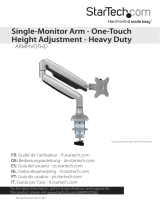
4A. Pending thickness of VESA compatible device, use provided
screws M-A or M-B along with washer (M-C) as shown above. Longer
screws for thicker monitor / devices. Load capacity of 19.8 lbs and 32”
screen max. Decide which VESA plate to use. If you want to have a
security VESA plate, select that particular VESA(D). If you want to go
with the non-security version, selection that particular VESA (C). Align
VESA holes of VESA plate (C or D) with device and rotate in screws
using screwdriver (not included) until securely tightened.
5C. When making swivel adjustments to the arm, use provided tool (P) at the joint above the mount as
shown above. Loosen to allow for swivel rotation as shown. Then rotate clockwise to tighten again
once desired rotation has been set for preferred setup.
6A. Identify the (3) components needed for cable routing. There is a clipped tray at the upper arm (A), a cover piece at the lower
arm (B) and then a hook at the base L-Bracket(F). Remove the clipped tray at the upper arm and then slide off the cover for the
lower arm. Plug one end of the cable to your device as shown above. Fish the cord under the upper arm, then clip on the tray.
Then continue to fish the cord to the lower arm through the arm. Re-cover the channel with the cover piece Lastly hook the wire
onto L-Bracket back (F) and then continue fishing the cord towards the outlet or power source.
**Monitor not
included and for
illustration
purposes only
**Monitor not
included and for
illustration
purposes only
**Monitor not
included and for
illustration
purposes only
7A. Loosen the joint (as shown) behind the VESA plate using provided tool (P). When loose, tilt up and
down or rotate portrait / landscape for preferred viewing angles and setup. When done, tighten screw again
until securely fastened.
8A. When fully finished with setup,
place the provided tools (Q, P) in the
tool organizer (F) as shown for easy
clamp angle and orientation
adjustments when needed.
5A. To properly balance the arms with monitors mounted, adjust the spring
tension using the provided allen key. Position it in the horizontal position and
firmly hold the arm as shown. Tight the screw to fix it in the horizontal position.
5B. To adjust the arm to the
desired height and configuration,
remove the back joint cover as
shown. Then using provided tool
(Q), rotate to loosen and firmly
push/pull arm into position, then
rotate screw opposite direction to
tighten.
WHEN USING SECURITY VESA PLATE (D) WHEN USING NON-SECURITY VESA PLATE (C)
4B. Combine device with VESA plate attached with rest of clamp by
sliding in at the grooves at the joint.
Afterwards, using provided tool (O), rotate key component to the locked
position to securely connect everything in place. Make sure to unlock
joint when needing to remove monitor.
4C. Combine device with VESA plate attached with rest of clamp by sliding in at the
grooves at the joint.
Afterwards,simply rotate knob to the locked position to secure the connection. And
rotate to the unlocked position when needing to remove VESA plate and monitor
together.
**Monitor not
included and for
illustration
purposes only
/