2 of 10
ISSUED: 03-08-11 SHEET #: 125-9195-5 09-20-12
Visit the Peerless Web Site at www.peerlessmounts.com For customer care call 1-800-865-2112.
BA
F
E
D
C
G
J
IH
K
L M
N O
P
Q
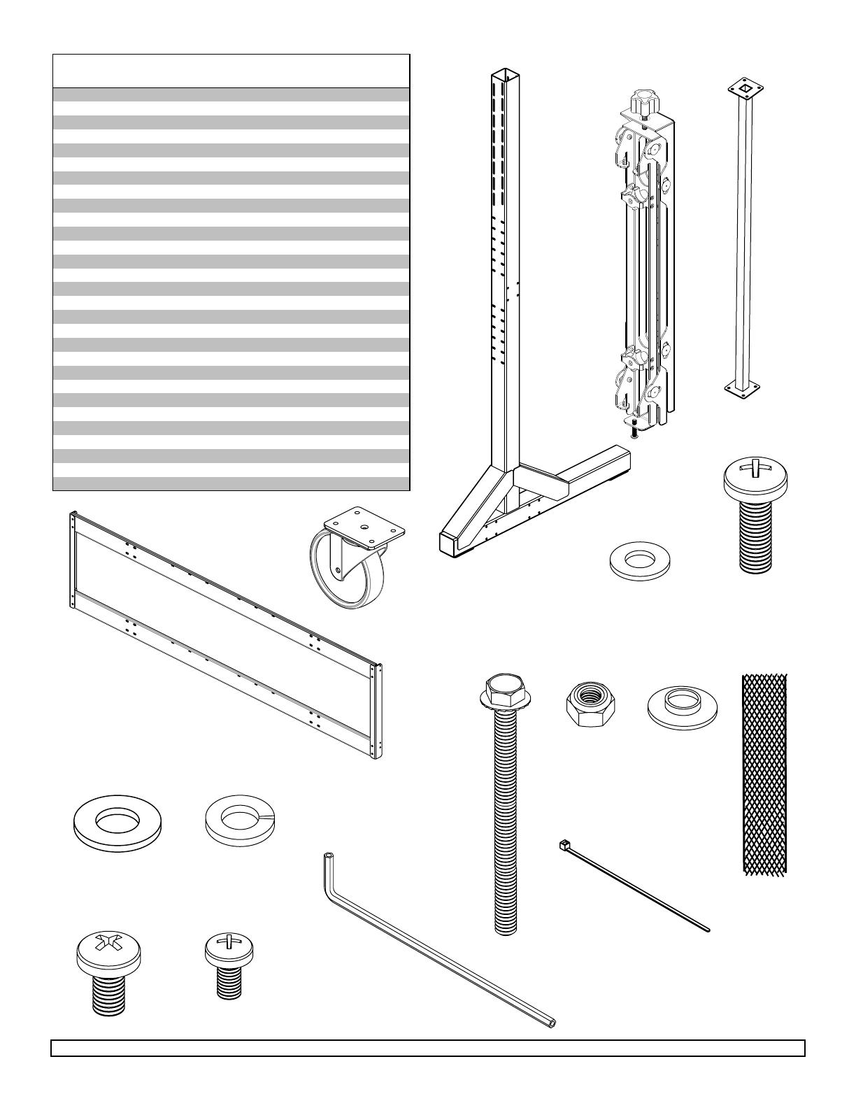
PARTS LIST
Description Qty. Part #
vertical support 2 145-1389
B adapter brackets 8 145-1711
C horizontal support 3 124-1852
D horizontal rail 2 145-1238
E 5" caster 4 600-0026
F 1/4" flat washer 56 540-9440
G M8 x 25 mm phillips screw 16 520-1031
H 5/16 flat washer 16 540-9406
I 5/16 split washer 16 540-9405
J 1/4-20 x 3.5" hex head screw 56 520-1656
K 1/4-20 nylock nut 56 530-9413
L .38 OD x .06 LG nylon washer 16 590-2233
M 18" mesh sleeve 4 600-1014
N M8 x 16 mm phillips screw 16 520-9257
O M6 x 12 mm phillips screw 16 520-1128
P 4 mm allen wrench 4 560-9646
Q cable tie 8 560-9711
R tube cap 2 590-1289
S M5 x 10 mm socket pin screw (not used) 8 520-1164
T #14 fender washer (not used) 16 540-1008
U front bottom cover 1 145-1364
back bottom cover 1 145-1363
W component shelf 1 145-1361
side cover 2 145-1362
decorative screw 12 520-2326
Z spacer 4 590-1136
A
front top cover 1 145-1388
BB back top cover 1 145-1368
CC self-drilling phillips screw 3 520-1320


