2 of 13
ISSUED: 11-16-11 SHEET #: 125-9265-2 02-24-12
Visit the Peerless Web Site at www.peerlessmounts.com For customer care call 1-800-865-2112.
BA
F
E
D
C
G
J
IH
K
L M
N O P
Q
R
S T
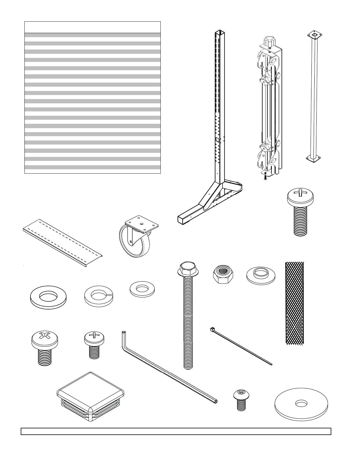
PARTS LIST
Description Qty. Part #
vertical support 2 145-1543
B adapter brackets 18 145-1711
C horizontal support 3 145-1382
D shelf 1 145-1361
E 5" caster 4 600-0026
F 1/4" flat washer 48 540-9440
G M8 x 25 mm phillips screw 16 520-1031
H 5/16 flat washer 16 540-9406
I 5/16 split washer 16 540-9405
J 1/4-20 x 3.5" hex head screw 48 520-1656
K 1/4-20 nylock nut 48 530-9413
L .38 OD x .06 LG nylon washer 36 590-2233
M 18" mesh sleeve 9 600-1014
N M8 x 16 mm phillips screw 36 520-9257
O M6 x 12 mm phillips screw 36 520-1128
P 4 mm allen wrench 9 560-9646
Q cable tie 18 560-9711
R tube cap 2 590-1289
S M5 x 10 mm socket pin screw (not used) 18 520-1164
T #14 fender washer (not used) 36 540-1008
U lower front cover 1 145-1505
lower back cover 1 145-1384
W upper cover 2 145-1450
rail connection bracket 6 145-1503
horizontal rail 6 145-1447
Z side cover 2 145-1362
A
M5 x 10 mm phillips screw 40 520-1233
BB flat washer 40 540-9400
CC lock washer 40 540-1035
DD decorative screw 14 520-2326
EE spacer 4 590-1136
FF self-drilling screw 3 520-1320
GG connection bracket 4
145-1504
HH M6 x 16 mm phillips screw 36 520-9274


