
DULCOTEST
®
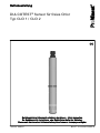
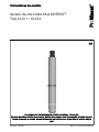
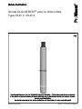
Sensor for free chlorine
Type CLO 1 / CLO 2
Assembly and operating instructions
EN/DE/FR/ES
Part no. 986347 BA DT 101 05/09 EN/DE/FR/ES
Please carefully read these operating instructions before use. · Do not discard.
The operator shall be liable for any damage caused by installation or operating errors.
The latest version of the operating instructions are available on our homepage.

Overall Table of Contents
EN
DULCOTEST
®
Sensor for free chlorine Type CLO 1 / CLO 2 ............................... 6
1 Introduction ....................................................................................................... 9
1.1 Explanation of the safety information............................................................. 9
1.2 Users' qualifications ..................................................................................... 11
1.3 General safety information .......................................................................... 12
1.4 Correct and Proper Use............................................................................... 13
1.5 Information in the event of an emergency ................................................... 13
2 Functional Description .................................................................................... 14
2.1 Construction ................................................................................................ 14
2.2 Measured variable ....................................................................................... 14
2.3 Function ....................................................................................................... 15
2.4 Construction of the sensor .......................................................................... 16
3 Transport and Storage ................................................................................... 18
3.1 Storage ........................................................................................................ 18
3.2 Transport...................................................................................................... 18
4 Assembly ........................................................................................................ 19
5 Installation ...................................................................................................... 22
6 Commissioning ............................................................................................... 24
6.1 Calibration ................................................................................................... 24
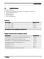
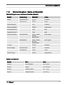
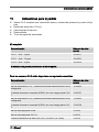
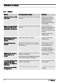
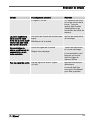
7 Troubleshooting .............................................................................................. 27
7.1 Troubleshooting ........................................................................................... 27
7.2 Error ............................................................................................................ 31
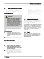
8 Maintenance and Repair ................................................................................ 33
8.1 Replacement intervals ................................................................................. 33
8.2 Repair........................................................................................................... 33
9 Decommissioning, Removal and Disposal ..................................................... 34
10 Ordering Information .................................................................................... 35
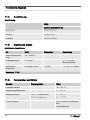
11 Technical Specifications ............................................................................... 36
11.1 Observed regulations/standards (minimum requirement) ......................... 36
11.2 Technical data ........................................................................................... 36
11.3 Material data / Dimensions and weights .................................................... 37
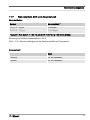
11.4 Flow ........................................................................................................... 38
11.5 Electrical data ............................................................................................ 38
11.6 Temperature and climate .......................................................................... 38
11.7 Rated gradient, drift and response time .................................................... 39
Overall Table of Contents
2
Page is loading ...
Page is loading ...
Page is loading ...

DULCOTEST
®
Sensor for free chlorine
Type CLO 1 / CLO 2
Operating instructions
EN
Part no. 986347 BA DT 101 05/09 EN/DE/FR/ES
Please carefully read these operating instructions before use. · Do not discard.
The operator shall be liable for any damage caused by installation or operating errors.
The latest version of the operating instructions are available on our homepage.

Table of contents
1 Introduction ............................................................................................................ 9
1.1 Explanation of the safety information............................................................. 9
1.2 Users' qualifications ..................................................................................... 11
1.3 General safety information .......................................................................... 12
1.4 Correct and Proper Use............................................................................... 13
1.5 Information in the event of an emergency ................................................... 13
2 Functional Description ......................................................................................... 14
2.1 Construction ................................................................................................ 14
2.2 Measured variable ....................................................................................... 14
2.3 Function ....................................................................................................... 15
2.4 Construction of the sensor .......................................................................... 16
3 Transport and Storage ......................................................................................... 18
3.1 Storage ........................................................................................................ 18
3.2 Transport...................................................................................................... 18
4 Assembly ............................................................................................................. 19
5 Installation ............................................................................................................ 22
6 Commissioning .................................................................................................... 24
6.1 Calibration ................................................................................................... 24
7 Troubleshooting ................................................................................................... 27
7.1
Troubleshooting ........................................................................................... 27
7.2 Error ............................................................................................................ 31
8 Maintenance and Repair ...................................................................................... 33
8.1
Replacement intervals ................................................................................. 33
8.2 Repair........................................................................................................... 33
9 Decommissioning, Removal and Disposal .......................................................... 34
10 Ordering Information ............................................................................................ 35
11 Technical Specifications ...................................................................................... 36
11.1
Observed regulations/standards (minimum requirement) ......................... 36
11.2 Technical data ........................................................................................... 36
11.3 Material data / Dimensions and weights .................................................... 37
11.4 Flow ........................................................................................................... 38
11.5 Electrical data ............................................................................................ 38
Table of contents
7

11.6 Temperature and climate .......................................................................... 38
11.7 Rated gradient, drift and response time .................................................... 39
12 Index..................................................................................................................... 40
Table of contents
8

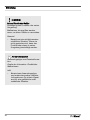
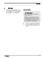
1 Introduction
These operating instructions provide infor‐
mation on the technical data and functions
of the product DULCOTEST
®
Sensor for
free chlorine, Type CLO 1 / CLO 2
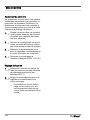
1.1 Explanation of the safety
information
Introduction
These operating instructions provide infor‐
mation on the technical data and functions
of the product. These operating instruc‐
tions provide detailed safety information
and are provided as clear step-by-step
instructions.
The safety information and notes are cate‐
gorised according to the following
scheme. A number of different symbols
are used to denote different situations.
The symbols shown here serve only as
examples.
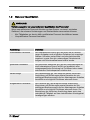
DANGER!
Nature and source of the danger
Consequence: Fatal or very serious
injuries.
Measure to be taken to avoid this
danger
Danger!
– Denotes an immediate threat‐
ening danger. If this is disre‐
garded, it will result in fatal or
very serious injuries.
WARNING!
Nature and source of the danger
Possible consequence: Fatal or very
serious injuries.
Measure to be taken to avoid this
danger
Warning!
– Denotes a possibly hazardous sit‐
uation. If this is disregarded, it
could result in fatal or very
serious injuries.
CAUTION!
Nature and source of the danger
Possible consequence: Slight or
minor injuries, material damage.
Measure to be taken to avoid this
danger
Caution!
– Denotes a possibly hazardous sit‐
uation. If this is disregarded, it
could result in slight or minor inju‐
ries. May also be used as a
warning about material damage.
Introduction
9

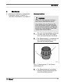
NOTICE!
Nature and source of the danger
Damage to the product or its sur‐
roundings
Measure to be taken to avoid this
danger
Note!
– Denotes a possibly damaging sit‐
uation. If this is disregarded, the
product or an object in its vicinity
could be damaged.
Type of information
Hints on use and additional informa‐
tion
Source of the information, additional
measures
Information!
–
Denotes hints on use and other
useful information. It does not
indicate a hazardous or dam‐
aging situation.
Introduction
10

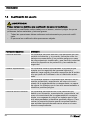
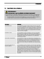
1.2 Users' qualifications
WARNING!
Danger of injury with inadequately qualified personnel!
If inadequately qualified personnel work on the sensor, this could result in dangers
that could cause serious injuries and material damage.
– All work on the unit should therefore only be conducted by qualified personnel.
– Keep unqualified personnel away.
Training Definition
Instructed personnel An instructed person is deemed to be a person who has
been instructed and, if required, trained in the tasks
assigned to him/her and possible dangers that could
result from improper behaviour, as well as having been
instructed in the required protective equipment and pro‐
tective measures.
Trained user A trained user is a person who fulfills the requirements
made of an instructed person and who has also received
additional training specific to the system from ProMinent
or another authorised distribution partner.
Technical experts A technical expert is deemed to be a person who is able
to assess the tasks assigned to him and recognize pos‐
sible hazards based on his/her technical training and
experience, as well as knowledge of pertinent regula‐
tions.
Trained qualified personnel A qualified employee is deemed to be a person who is
able to assess the tasks assigned to him and recognize
possible hazards based on his/her training, knowledge
and experience, as well as knowledge of pertinent regu‐
lations. The assessment of a person's technical training
can also be based on several years of work in the rele‐
vant field.
Introduction
11

Training Definition
Electrician Electricians are deemed to be people, who are able to
complete work on electrical systems and recognize and
avoid possible hazards independently based on his/her
technical training and experience, as well as knowledge
of pertinent standards and regulations.
Electricians should be specifically trained for the working
environment in which they are employed and know the
relevant standards and regulations.
Electricians must comply with the provisions of the appli‐
cable statutory directives on accident prevention.
Customer Service depart‐
ment
Customer Service department refers to service techni‐
cians, who have received proven training and have been
authorised by ProMinent to work on the system.
Note for the system operator
The pertinent accident prevention regulations, as well as all other generally acknowl‐
edged safety regulations, must be adhered to!
1.3 General safety information
WARNING!
Unauthorised access!
Possible consequence: Fatal or very
serious injuries
– Measure: Ensure that there can
be no unauthorised access to the
unit
– The sensor may only be fitted,
installed, serviced and operated
by personnel trained for this
CAUTION!
Functional limitations
Possible consequence: Slight or
minor injuries, material damage
– Check the sensor regularly for dirt
and impurities
– Check the membrane cap regu‐
larly for air bubbles adhering to it
– Observe all applicable national
regulations relating to mainte‐
nance, service and calibration
intervals.
Introduction
12

CAUTION!
Prerequisites for operation
Possible consequence: Slight or
minor injuries, material damage
– The sensor may only be used in
flow gauges that ensure the cor‐
rect flow parameters.
– There must be a free outlet or at
most a counter pressure of 1 bar
at the outlet of the flow gauge.
The maximum operating pressure
of the respective single compo‐
nents must be observed.
– The sensor's voltage supply may
not be interrupted
– Following longer interruptions to
the voltage supply (> 2 h), allow
the sensor to run-in again and
recalibrate it
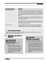
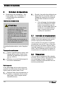
1.4 Correct and Proper Use
NOTICE!
Correct and Proper Use
– The sensor may only be used to
determine and regulate concen‐
trations of free chlorine
– The sensor may not be used in
conjunction with organic chlorine
compounds, such as trichloroiso‐
cyanuric acid, or stabilisers, such
as cyanuric acid
– Any other uses or modifications
to the system are prohibited
– The sensor is not a safety com‐
ponent
1.5 Information in the event of
an emergency
n In the event of an emergency, switch
off the controller
n If liquid exits from the flow gauge
housing then close the shut-off valves
provided by the customer at their
inlets and outlets
n Observe the safety instructions of the
plant operator before opening the flow
gauge housing
n In case of proven over-metering,
destroy the excess chlorine using a
suitable reducing agent (e.g.
hydrogen peroxide or sodium sul‐
phite)
Introduction
13

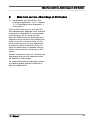
2 Functional Description
Brief functional description
The DULCOTEST
®
Sensor for free
chlorine CLO 1 / CLO 2 is an ampero‐
metric three-electrode sensor without a
membrane. The DULCOTEST
®
Sensor for
free chlorine CLO 1 / CLO 2 can be used
to determine the concentration of free
chlorine in water.
The DULCOTEST
®
Sensor for free
chlorine CLO 1 / CLO 2 measures the
content of hypochlorous acid (HOCl) in
water.
Typical applications:
n chlorination of swimming bath water
(CLO 1)
n chlorination of drinking water (CLO 1)
n combating legionella in house water
installations up to 70 °C (CLO 2)
The sensor signal depends on the con‐
ductivity of the sample medium.
The sensor signal is flow-dependent. The
rate of flow in the DGMA module must
therefore be kept constant at ± 5 l/h.
2.1 Construction
The DULCOTEST
®
Sensor for free
chlorine CLO 1 / CLO 2 is an open, three-
electrode sensor without a membrane. It
comprises a sensor cap and the sensor
shaft. The electrolyte-filled sensor cap
constitutes the reference system. The
ring-shaped reference electrode in the
measuring chamber is above the electro‐
lyte and contacts with the working elec‐
trode (cathode) and the counter electrode
(anode).
Both electrodes on the sensor shaft are
immersed in the measuring (sample)
water. The amplifier electronics are
located in the sensor shaft. The electrical
connection is above this.
The temperature sensor for temperature
compensation is incorporated in the lower
part of the sensor shaft .
2.2 Measured variable
CAUTION!
Oxidising agent
Possible consequence: Slight or
minor injuries, material damage
If there are additional oxidising agents
in the sample medium such as, e.g.
chlorine dioxide, ozone or chloramine
then these are also detected by the
sensor. In other words, the sensor is
not specifically calibrated for chlorine
but detects all oxidising agents in the
sample media.
This should be considered when con‐
figuring the process to prevent incor‐
rect measurement and concomitant
incorrect metering.
Free chlorine (HOCI, OCI
-
, Cl
2
). Free
chlorine is the sum of chlorine gas (Cl
2
),
hypochlorous acid (HOCI) and hypo‐
chlorite (OCI
-
).
Functional Description
14

2.3 Function
Gold wires with a diameter of 2 mm are
used as the working electrode (cathode)
and counter electrode (anode); a silver
ring coated with a layer of silver halide is
used as reference electrode. After the
sensor has been electrically connected to
the controller, a potentiostat is used to
ensure there is a constant polarisation
voltage for the required electrode reaction
on the working electrode, independent of
the current flow. The current flow (depo‐
larisation current) produced, which under
constant conditions is proportional to the
concentration of the hypochlorous acid, is
converted into a standard output signal
(4...20 mA) by the sensor electronics and
is displayed by the measuring device/con‐
trol device.
The photometric DPD-I method is used to
calibrate the DULCOTEST
®
sensor for
free chlorine CLO 1 / CLO 2.
Functional Description
15

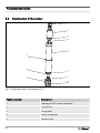
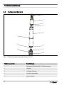
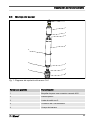
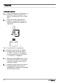
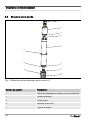
2.4 Construction of the sensor
1
2
3
4
5
6
7
8
9
10
11
Fig. 1: Exploded view of the sensor CLO
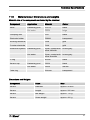
Position number Description
1 Opening for M12 cable connector
2 Top section
3 O-ring seal
4 2-lead connection
5 Sensor shaft
Functional Description
16

Position number Description
6 O-ring seal
7 Working electrode and counter electrode
8 Tubular seal and air vent opening
9 Sensor cap
10 Reference electrode
11 Clamping disc
Functional Description
17

3 Transport and Storage
NOTICE!
Original packaging
Damage to the product
– Only transport, ship and store the
sensor in its original packaging
– Retain the packaging in its
entirety including the polystyrene
inserts
NOTICE!
Maximum storage period
Damage to the product
If the sensor is stored for a long
period of time, return it to ProMinent
for checking or servicing. Otherwise
the safe operation and measuring
accuracy of the sensor can no longer
be guaranteed.
3.1 Storage
Permissible ambient temperature: +5 °C
to +50 °C
Humidity: maximum 90 % relative air
humidity, non-condensing
Other: no dust, no direct sunlight
Maximum storage period of the electro‐
lytes in their original packaging: see label
on the bottle
Maximum storage period of the sensor in
its original packaging and normal atmos‐
phere: 3 years
3.2 Transport
The sensor should be transported in its
original packaging and in compliance with
the permissible environmental conditions.
No further special conditions have to be
observed in relation to transport.
Transport and Storage
18

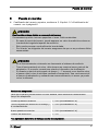
4 Assembly
n Users' qualifications: trained qualified
personnel, see
Ä Chapter 1.2 ‘Users'
qualifications ’ on page 11
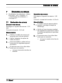
Electrolyte filling
NOTICE!
Perform the following work over a sink
After this, carefully re-close the elec‐
trolyte bottle. Unclosed electrolyte
bottles may severely limit the storage
period of the electrolytes.
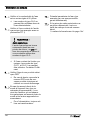
1. Remove the red end cap and cut off
the top end of the spout with a
knife.
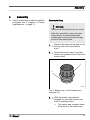
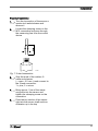
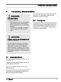
2. Screw the sensor cap (1) and the
sensor cap protector (2) off from the
sensor shaft
A0107
1
2
Fig. 2: Sensor cap (1) with sensor cap
protector (2)
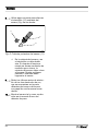
3. With the sensor cap protector
plugged on, place the sensor cap
onto a working surface
ð
The sensor cap protector seals
the bottom of the sensor cap.
Assembly
19

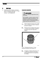
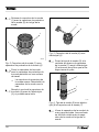
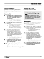
4. Fill the sensor cap (4) to the brim
with electrolyte (3) taking care to
avoid bubbles
A0108
3
4
Fig. 3: Sensor cap (4) with electrolyte (3)
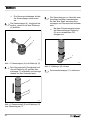
5. Place the sensor shaft (5) vertically
onto the sensor cap (7) filled with
electrolyte (6) and turn until the
thread catches
A0126
5
6
7
Fig. 4: Sensor shaft (5) with electrolyte (6)
and sensor cap (7)
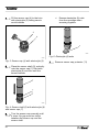
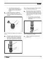
6. Turn the sensor cap manually until
it stops. No gap must be visible
between the sensor cap and the
sensor shaft
ð
Excess electrolyte (8) exits
from the openings when
screwing together.
A0127
8
Fig. 5: Electrolyte (8) exits
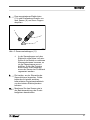
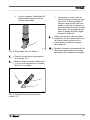
7. Remove sensor cap protector (11)
Assembly
20

8. Rinse the leaked electrolyte (10)
from the sensor (9) and from your
fingers under running water
A0128
9
10
11
Fig. 6: Remove sensor cap protector (11)
ð
There should be no air in the
sensor cap and the electrolyte.
If the measuring results are
unclear during operation then
the sensor cap must be re-
filled. If the problem persists
then the sensor must be regen‐
erated by ProMinent.
9. Free the two gold electrodes on the
face side of the sensor body from
any remaining electrolyte using a
soft, moistened paper towel
10. Fit the sensor as described in the
operating manual for the flow
gauge .
Assembly
21

5 Installation
n Users' qualifications: trained qualified
personnel or electrician, see
Ä Chapter 1.2 ‘Users' qualifications ’
on page 11
CAUTION!
Incorrect metering
Possible consequence: Slight or
minor injuries, material damage
– Do not switch off the measuring
system during intermittent opera‐
tion
– Switch on the metering
equipment with a time delay
if necessary
– The water to be measured must
always contain a sufficient quan‐
tity of the appropriate metering
medium
– Otherwise you will have to
reckon with longer run-in
times
WARNING!
Connection to external devices
Possible consequence: Fatal or very
serious injuries
– The measuring device/control
device connected must be gal‐
vanically isolated from the
sensor!
– Do not allow the supply voltage to
fall below 16 V DC, even for short
periods of time
– The power source must be
able to work with a minimum
of 35 mA at a minimum of 16
V DC
– Too low a supply voltage
may result in an incorrect
reading
The interface requirements are automati‐
cally met when connecting to ProMinent
control devices.
Installation
22

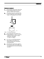
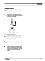
Electrical Installation
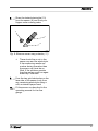
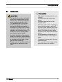
1. Turn the top section of the sensor a
quarter turn anticlockwise and
remove it
2. Loosen the clamping screw on the
M12 connection and pass through
the measuring line from the control
device
A0102
Fig. 7: 2-lead connection
3. Strip the ends of the cables, fit
cable end sleeves
( ⌀ max = 0.5 mm
2
) and connect to
the 2-lead connection:
1 = plus, 2 = minus
4. Bring approx. 5 cm of the meas‐
uring wire into the sensor and
tighten the clamping screw on the
connection
5. Push the top section of the sensor
right into the sensor shaft and turn
clockwise up to its stop
Installation
23
Page is loading ...
Page is loading ...
Page is loading ...
Page is loading ...
Page is loading ...
Page is loading ...
Page is loading ...
Page is loading ...
Page is loading ...
Page is loading ...
Page is loading ...
Page is loading ...
Page is loading ...
Page is loading ...
Page is loading ...
Page is loading ...
Page is loading ...
Page is loading ...
Page is loading ...
Page is loading ...
Page is loading ...
Page is loading ...
Page is loading ...
Page is loading ...
Page is loading ...
Page is loading ...
Page is loading ...
Page is loading ...
Page is loading ...
Page is loading ...
Page is loading ...
Page is loading ...
Page is loading ...
Page is loading ...
Page is loading ...
Page is loading ...
Page is loading ...
Page is loading ...
Page is loading ...
Page is loading ...
Page is loading ...
Page is loading ...
Page is loading ...
Page is loading ...
Page is loading ...
Page is loading ...
Page is loading ...
Page is loading ...
Page is loading ...
Page is loading ...
Page is loading ...
Page is loading ...
Page is loading ...
Page is loading ...
Page is loading ...
Page is loading ...
Page is loading ...
Page is loading ...
Page is loading ...
Page is loading ...
Page is loading ...
Page is loading ...
Page is loading ...
Page is loading ...
Page is loading ...
Page is loading ...
Page is loading ...
Page is loading ...
Page is loading ...
Page is loading ...
Page is loading ...
Page is loading ...
Page is loading ...
Page is loading ...
Page is loading ...
Page is loading ...
Page is loading ...
Page is loading ...
Page is loading ...
Page is loading ...
Page is loading ...
Page is loading ...
Page is loading ...
Page is loading ...
Page is loading ...
Page is loading ...
Page is loading ...
Page is loading ...
Page is loading ...
Page is loading ...
Page is loading ...
Page is loading ...
Page is loading ...
Page is loading ...
Page is loading ...
Page is loading ...
Page is loading ...
Page is loading ...
Page is loading ...
Page is loading ...
Page is loading ...
Page is loading ...
Page is loading ...
Page is loading ...
Page is loading ...
Page is loading ...
Page is loading ...
Page is loading ...
Page is loading ...
Page is loading ...
Page is loading ...
Page is loading ...
Page is loading ...
Page is loading ...
Page is loading ...
Page is loading ...
Page is loading ...
Page is loading ...
Page is loading ...
Page is loading ...
Page is loading ...
Page is loading ...
Page is loading ...
Page is loading ...
Page is loading ...
Page is loading ...
Page is loading ...
Page is loading ...
Page is loading ...
Page is loading ...
Page is loading ...
Page is loading ...
Page is loading ...
-
 1
1
-
 2
2
-
 3
3
-
 4
4
-
 5
5
-
 6
6
-
 7
7
-
 8
8
-
 9
9
-
 10
10
-
 11
11
-
 12
12
-
 13
13
-
 14
14
-
 15
15
-
 16
16
-
 17
17
-
 18
18
-
 19
19
-
 20
20
-
 21
21
-
 22
22
-
 23
23
-
 24
24
-
 25
25
-
 26
26
-
 27
27
-
 28
28
-
 29
29
-
 30
30
-
 31
31
-
 32
32
-
 33
33
-
 34
34
-
 35
35
-
 36
36
-
 37
37
-
 38
38
-
 39
39
-
 40
40
-
 41
41
-
 42
42
-
 43
43
-
 44
44
-
 45
45
-
 46
46
-
 47
47
-
 48
48
-
 49
49
-
 50
50
-
 51
51
-
 52
52
-
 53
53
-
 54
54
-
 55
55
-
 56
56
-
 57
57
-
 58
58
-
 59
59
-
 60
60
-
 61
61
-
 62
62
-
 63
63
-
 64
64
-
 65
65
-
 66
66
-
 67
67
-
 68
68
-
 69
69
-
 70
70
-
 71
71
-
 72
72
-
 73
73
-
 74
74
-
 75
75
-
 76
76
-
 77
77
-
 78
78
-
 79
79
-
 80
80
-
 81
81
-
 82
82
-
 83
83
-
 84
84
-
 85
85
-
 86
86
-
 87
87
-
 88
88
-
 89
89
-
 90
90
-
 91
91
-
 92
92
-
 93
93
-
 94
94
-
 95
95
-
 96
96
-
 97
97
-
 98
98
-
 99
99
-
 100
100
-
 101
101
-
 102
102
-
 103
103
-
 104
104
-
 105
105
-
 106
106
-
 107
107
-
 108
108
-
 109
109
-
 110
110
-
 111
111
-
 112
112
-
 113
113
-
 114
114
-
 115
115
-
 116
116
-
 117
117
-
 118
118
-
 119
119
-
 120
120
-
 121
121
-
 122
122
-
 123
123
-
 124
124
-
 125
125
-
 126
126
-
 127
127
-
 128
128
-
 129
129
-
 130
130
-
 131
131
-
 132
132
-
 133
133
-
 134
134
-
 135
135
-
 136
136
-
 137
137
-
 138
138
-
 139
139
-
 140
140
-
 141
141
-
 142
142
-
 143
143
-
 144
144
-
 145
145
-
 146
146
-
 147
147
-
 148
148
-
 149
149
-
 150
150
-
 151
151
-
 152
152
-
 153
153
-
 154
154
-
 155
155
-
 156
156


ProMinent DULCOTEST CLO 1 Assembly And Operating Instructions Manual
- Type
- Assembly And Operating Instructions Manual
- This manual is also suitable for
Ask a question and I''ll find the answer in the document
Finding information in a document is now easier with AI
in other languages
- français: ProMinent DULCOTEST CLO 1
- español: ProMinent DULCOTEST CLO 1
- Deutsch: ProMinent DULCOTEST CLO 1
Related papers
-
ProMinent DULCOTEST CDR 1 Assembly And Operating Instructions Manual
-
-
-
-
-
-
-
-
-
Other documents
-
DGM T-814DH User manual
-
Omega CLDTX-100 Series Owner's manual
-
 EcoloxTech 240 Operating instructions
-
AVENTICS Volume Meter, 553-001 Operating instructions
-
-
Graco 3A1149D User manual
-
Wohler WA 335 User manual
-
VOLTCRAFT PHT-02 ATC pH Meter Stick 0-14pH User manual
-
Pool Technologie Poolsquad User manual
-
Grundfos Oxiperm Pro OCD-162 Service Instructions Manual
