Page is loading ...

1
DEUTSCHENGLISH FRANÇAIS ITALIANO ESPAÑOL NEDERLANDS
PORTUGUÊS SVENSKA
DEUTSCHENGLISHFRANÇAISITALIANOESPAÑOLNEDERLANDS PORTUGUÊS
SVENSKA
© HAAG-STREIT AG, 3098 Koeniz, Switzerland - HS Doc. no. 1500.7220505-04010 – 2015 – 08 DOC. No. 1500 1500.1400209.04000
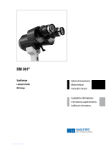
INSTRUCTIONS FOR USE
Slit lamp
BI 900®
1. edition / 2015 – 08
01-IFU_BI900-7220505-04010_eng.indd 1 12.08.2015 14:37:46

2
DEUTSCHENGLISH FRANÇAIS ITALIANO ESPAÑOL NEDERLANDS
PORTUGUÊS SVENSKA
DEUTSCHENGLISHFRANÇAISITALIANOESPAÑOLNEDERLANDS PORTUGUÊS
SVENSKA
© HAAG-STREIT AG, 3098 Koeniz, Switzerland - HS Doc. no. 1500.7220505-04010 – 2015 – 08
INSTRUCTIONS FOR USE
Slit lamp
BI 900®
1. edition / 2015 – 08
Introduction
Thank you for choosing a HAAG-STREIT device. Provided you comply carefully
with the regulations in this instructions for use, we can guarantee the reliable and
unproblematic use of our product.
Purpose of use
A
slit lamp biomicroscope is intended for use in eye examination. It is used to aid in
the diagnosis and documentation of diseases or trauma which affect the structural
properties of the eye.
Contraindication
There are no absolute contraindications known for examinations with this device.
Appropriate professional assessment and caution are necessary.
WARNING!
Read the instruction manual carefully before commissioning this pro-
duct. It contains important information regarding the safety of the user
and patient.
NOTE!
Federal law restricts this device to sale by or on the order of a physician
or licensed practitioner.
WARNING!
This device is equipped with high intensity light emitting diodes. Exces-
sive exposure of patients in treatment with certain medication may lead
to phototoxic adverse reactions, due to higher photosensitivity.
01-IFU_BI900-7220505-04010_eng.indd 2 12.08.2015 14:37:46

3
DEUTSCHENGLISH FRANÇAIS ITALIANO ESPAÑOL NEDERLANDS
PORTUGUÊS SVENSKA
DEUTSCHENGLISHFRANÇAISITALIANOESPAÑOLNEDERLANDS PORTUGUÊS
SVENSKA
© HAAG-STREIT AG, 3098 Koeniz, Switzerland - HS Doc. no. 1500.7220505-04010 – 2015 – 08
Contents
1. Safety ...................................................................................4
1.1 Areas of application of the device ...........................................................................4
1.2 Ambient conditions ..................................................................................................4
1.3 Shipment and unpacking ........................................................................................4
1.4 Installation warnings ..............................................................................................4
1.5 Operation, environment ..........................................................................................4
1.5 Light toxicity ............................................................................................................5
1.7 Disinfection .............................................................................................................5
1.8 Warranty and product liability ..................................................................................5
1.9 Symbols ..................................................................................................................5
2. Introduction ..........................................................................6
2.1 Overview .................................................................................................................6
2.2 Overview LED illumination ......................................................................................6
2.3 LED illumination LI02 ..............................................................................................7
2.4 Bluelter .................................................................................................................7
2.5 Periphery or background illumination .....................................................................7
3. Appliance assembly / installation ......................................7
3.1 Placement of adhesive label for the automatic
left/right detection ....................................................................................................7
3.2 Camera assembly ...................................................................................................7
3.3 Cabling of the RM02 (diagram) ...............................................................................8
3.4 Microscope and illumination ....................................................................................8
3.5 Regulating the clearance of the slit width control ....................................................8
3.6 Step-by-step cabling ...............................................................................................9
4. Startup ................................................................................10
4.1 Switching on the device ........................................................................................10
5. Operation ............................................................................10
5.1 Setting the eyepieces ............................................................................................10
5.2 Field of view .........................................................................................................10
5.3 White balance ......................................................................................................10
5.3.1 Slit lamp preparation ............................................................................................10
5.3.2 Conducting a white balance ..................................................................................10
5.4 Software / Help menu / Error messages ...............................................................11
5.5 Preparing the patient ............................................................................................11
5.6 Operating the instrument ......................................................................................12
5.7 Settingthelters&diaphragms ...........................................................................13
5.8 Fixation star ..........................................................................................................13
5.9 Microscope and eyepiece ....................................................................................13
5.10 Reduced operation ................................................................................................13
5.11 LED display Illumination head ...............................................................................13
5.12 LED display power supply .....................................................................................13
5.13 LED display release module RM02 .......................................................................14
5.14 LED display camera ..............................................................................................14
5.15 Error messages (illumination head) ......................................................................14
5.16 Error messages release module RM02.................................................................14
5.17 Error messages camera ........................................................................................15
5.18 Software / Help menu / Error messages ...............................................................15
6. Decommissioning ..............................................................15
7 Technical data ...................................................................15
7.1 Slit illumination .....................................................................................................15
7.2 Power supply .......................................................................................................15
7.3 Stereo microscope ...............................................................................................15
7.4 Instrument base ...................................................................................................16
7.5 Dimensions ...........................................................................................................16
7.6 Camera .................................................................................................................16
7.7 Minimum PC requirements ..................................................................................16
8. Maintenance .......................................................................16
8.1 Device inspection ..................................................................................................16
8.2 Servicing ...............................................................................................................16
8.3 Cleaning ................................................................................................................17
8.4 Replacing the illumination mirror ...........................................................................17
8.5 Dust cover .............................................................................................................17
A. Appendix ............................................................................17
A.1 Accessories / spare parts ......................................................................................17
B. Statutory requirements ....................................................17
C. Classication ....................................................................17
D. Disposal ..............................................................................18
E. Observed standards .......................................................... 18
F. Information and manufacturer's declaration
concerning electromagnetic compatibility
(EMC) ..................................................................................19
F.1 General .................................................................................................................19
F.2 Emitted interference (standard table 1) .................................................................19
F.3 Interference immunity (standard table 2) ..............................................................20
F.4 Interference immunity for non-life-supporting devices (standard table 4) .............21
F.5 Safe distances for non-life-supporting devices (standard table 6) ........................22
01-IFU_BI900-7220505-04010_eng.indd 3 12.08.2015 14:37:46

4
DEUTSCHENGLISH FRANÇAIS ITALIANO ESPAÑOL NEDERLANDS
PORTUGUÊS SVENSKA
DEUTSCHENGLISHFRANÇAISITALIANOESPAÑOLNEDERLANDS PORTUGUÊS
SVENSKA
© HAAG-STREIT AG, 3098 Koeniz, Switzerland - HS Doc. no. 1500.7220505-04010 – 2015 – 08
1. Safety
DANGER!
Failure to comply with these instructions may result in material damage
or pose a danger to patients or users.
WARNING!
These warnings must absolutely be complied with to guarantee
safe operation of the device and to avoid any danger to users and
to patients.
NOTE!
Important information: please read carefully.
1.1 Areas of application of the device
The device is intended for use in doctor's practices, hospitals and optometrists' and
opticians' premises.
1.2 Ambient conditions
Transport: Temperature
Air pressure
Relative humidity
from
from
from
−40°C
500 hPa
10%
to
to
to
+70°C
1060 hPa
95%
Storage:
Temperature
Air pressure
Relative humidity
from
from
from
−10°C
700 hPa
10%
to
to
to
+55°C
1060 hPa
95%
Use:
Temperature
Air pressure
Relative humidity
from
from
from
+10°C
800 hPa
30%
to
to
to
+35°C
1060 hPa
90%
1.3 Shipment and unpacking
• Before you unpack the device, check whether the packaging shows traces of in-
correct handling or damage. If this is the case, notify the transport company that
has delivered the goods to you. Unpack the device together with a representative
of the transport company. Prepare a report for any possibly damaged parts. This
report must be signed by you and by the representative of the transport company.
• Leave the device in the packaging for a few hours before unpacking it (conden-
sation).
• Check the device for damage after it is unpacked. Return defective devices in the
appropriate packaging.
• Store packaging material carefully, so that it can be used for possible returns or
when moving.
• Theslitlampandheadrestmustbeinstalledonanelectricallyinsulated,re-re-
sistant table top.
• The rail covers (a) prevent the slit lamp from tilting.
• Check: Are the connection parts of the accessories in the correct position
(screwed connections, quick-release fasteners)?
(a)
1.4 Installation warnings
WARNING!
•
Do not modify this equipment without authorization of the manufacturer
.
Installation and repairs may only be performed by trained specialists.
Any third-party device must be connected in compliance with the
EN 60601-1 standard.
The device must not be stacked or placed in close proximity to other
electronic devices.
•
•
1.5 Operation, environment
DANGER!
Never use the device in potentially explosive environments where vola-
tile solvents (alcohol, petrol, etc.) and flammable anaesthetics are in
use.
WARNING!
The device must be switched off after every use. Otherwise there is a
risk of overheating when a protective dust cover is used.
01-IFU_BI900-7220505-04010_eng.indd 4 12.08.2015 14:37:47

5
DEUTSCHENGLISH FRANÇAIS ITALIANO ESPAÑOL NEDERLANDS
PORTUGUÊS SVENSKA
DEUTSCHENGLISHFRANÇAISITALIANOESPAÑOLNEDERLANDS PORTUGUÊS
SVENSKA
© HAAG-STREIT AG, 3098 Koeniz, Switzerland - HS Doc. no. 1500.7220505-04010 – 2015 – 08
NOTE!
This equipment must only be operated by qualified and trained person-
nel. The owner is responsible for their training. This device may only be
used in accordance with the instructions in "Purpose of use".
1.5 Light toxicity
WARNING!
As extended, intensive illumination can damage the retina, the use of
the device in the examination of the eye should not be prolonged un-
necessarily. The illumination of this slit lamp emits a radiation in the
range between 400 and 750nm. Detailed information on the radiation
can be provided on request. The retinal dose for a photochemical risk
is composed of the product of the radiance and the exposure time.
If the radiance is halved, the time until the exposure time limit value
is reached will double accordingly. To date, no acute, optical radia-
tion hazard has been detected in slit lamps. Nevertheless, we recom-
mend keeping the intensity of the light reaching the patient's retina to
the minimum possible for the respective diagnosis. Children, people
with aphakia and people suffering from eye conditions are most at risk.
An increased risk may also occur if the retina is exposed to the same
or a similar device with a visible light source within 24 hours. This ap-
plies,inparticular,iftheretinahasbeenphotographedwithaashbulb
in advance.
The light from this instrument may be dangerous. The risk of eye dam-
age increases with the exposure time. An exposure time with this in-
strument at maximum intensity of longer than 143 seconds exceeds
the guideline value for a risk in accordance with EN ISO 15004-2.
1.7 Disinfection
NOTE!
The device does not require disinfection. For more information on
cleaning, please refer to the 'Maintenance' section.
1.8 Warranty and product liability
Haag-Streit products must be used only for the purposes and in the manner des-
cribed in the documents distributed with the product.
The product must be treated as described in the ‘Safety’ chapter. Improper hand-
ling can damage the product. This would void all guarantee claims.
Continued use of a product damaged by incorrect handling may lead to personal
injury. In such a case, the manufacturer will not accept any liability.
Haag-Streit does not grant any warranties, either expressed or implied, including
implied warranties of merchantability or fitness for a particular use.
Haag-Streit expressly disclaims liability for incidental or consequential damage
resulting from the use of the product.
This product is covered by a limited warranty granted by your seller.
This product is covered by a limited warranty, which may be reviewed at
www.haag-streit-usa.com.
•
•
•
•
•
•
For US
A only:
•
1.9 Symbols
Read the instructions for use
attentively
General warning: Read the ac-
companying documentation
Notes on disposal, see the
'Disposal' chapter
This appliance fulfills the Euro-
pean Directive 2011/65/EU
(RoHS)
Year of production Manufacturer
European certificate of
conformity Earth (ground)
Direct current
Not protected from foreign
bodies
Serial number HS reference number
Strong permanent magnets Plug socket USB 3.0 micro
B on RM 02 for computer
01-IFU_BI900-7220505-04010_eng.indd 5 12.08.2015 14:37:49

6
DEUTSCHENGLISH FRANÇAIS ITALIANO ESPAÑOL NEDERLANDS
PORTUGUÊS SVENSKA
DEUTSCHENGLISHFRANÇAISITALIANOESPAÑOLNEDERLANDS PORTUGUÊS
SVENSKA
© HAAG-STREIT AG, 3098 Koeniz, Switzerland - HS Doc. no. 1500.7220505-04010 – 2015 – 08
Plug socket on RM 02 for
power supply Slit lamp illumination
Background illumination
2. Introduction
The BI 900 slit lamp comprises an illumination unit and a binocular microscope. The
entire device can be moved in front of the eyes using the instrument base. The il-
lumination offers a range of setting possibilities for making the practically invisible
areas of the eye visible. There is also a range of accessories available for the slit
lamp to allow special diagnosis possibilities in addition to the general examinations.
NOTE!
The BI 900 slit lamp can be optionally equipped with the imaging set
(HS art. no. 7220535).
2.1 Overview
1. Lamp cable with special connection
plug for LI02 plus
2. LED illumination LI 900
3. Filter lever
4. Optical light guide for periphery or
background illumination
5. Slitlength,slitrotation,bluelterand
xationstarcontrol,knobforrotat-
ing the slit
6. Scale for angled position of the slit
image (5° increments)
7. Periphery or background illumination
FI01f (standard)
8. Illumination mirror
9. Diffusing lens
10. Headrest (see separate instructions)
11. Protective cover
12. Illumination unit / microscope an-
gle scale
13. Illumination arm locking screw
1
2
3
4
5
6
7
8
9
10
11
12
13
14
15
16
17
18
19
20
21
22
23
24
25
26
27
28
29
30
32
33
34
9
8
35
31
2.2 Overview LED illumination
36. LED illumination LI02 plus with periphery or background lighting
37. Plug connection
38. Filterwheelforbluelter
39. Connection periphery or background illumination
40. Cover
14. Microscope arm locking screw
15. Camera cable
16. Release module RM02
17. Stickerleft/rightidentication
18. Axle
19. Rail cover
20. Cover cap for the accessories base
21. Stereo microscope
22. Eyepieces
23. Mounting screw for breath shield
(option)
24. Breath shield (option)
25. Centering screw for illumination
26. Camera operational control LED
27. Inclinationanglelatch0°−20°
28. Slit width controls
29. Roller rail
30. Control lever
31. Camera
32. Slide plate
33. EyeSuite Imaging software
34. Power supply
35. Electric power supply lead (country-
dependent)
01-IFU_BI900-7220505-04010_eng.indd 6 12.08.2015 14:37:51

7
DEUTSCHENGLISH FRANÇAIS ITALIANO ESPAÑOL NEDERLANDS
PORTUGUÊS SVENSKA
DEUTSCHENGLISHFRANÇAISITALIANOESPAÑOLNEDERLANDS PORTUGUÊS
SVENSKA
© HAAG-STREIT AG, 3098 Koeniz, Switzerland - HS Doc. no. 1500.7220505-04010 – 2015 – 08
36
37
38
39
40
41
41
2.3 LED illumination LI02
2.4 Bluelter
41. Therotatingwheelisusedtopivotthebluelter.Markingpointsatthesame
height=bluelterison.
2.5 Periphery or background
illumination
This periphery or background illumination may only be
used in conjunction with an LI02 plus LED illumination.
42. Peripheryorbackgroundillumination,xed
43. Periphery or background illumination, swiveling (op-
tion)
42 43
3. Appliance assembly / installation
WARNING!
Do not modify this equipment without authorization of the manufacturer.
Installation and repairs may only be performed by trained specialists.
Contact your HAAG-STREIT representative for installation, repairs and
modification work on the system. The contact details are available at
www.haag-streit.com.
3.1 Placement of adhesive label for the automatic
left/right detection
44. Protectivelm
45. Rest of the sticker
46. Table edge
• Remove rail cover (19) and place slit lamp aside. Clean surface of table.
• Removeprotectivelm(44)fromthebackoftheadhesivelabel.Carefullystartat
the corner opposite the black surface.
• Position the sticker against the right roller rail (29) and the edge of the table (46).
Pressrmlyonthewhite/blacksurface,pressawayanyairbubbles.
• Carefully tear off the remainder of the adhesive label (45) (the 'positioning tool')
along the perforation.
• Reassemble the slit lamp and rail cover.
45
29
46
19
44
3.2 Camera assembly
• Remove the cover caps from the camera and adapter.
• Screw the camera (48) onto the adapter.
• Position the image upright setting on the monitor: slightly loosen the 3 retaining
screws (47), turn the camera around its vertical axis until the position is correct;
reafxthecamera.Throughthesoftware,theimagecanbedisplayedhorizontally
or vertically.
• Mountthecameracasing(50)andxinplacewithscrews(49)
47. Retaining screws
48. Camera
49. Fastening screws
50. Camera casing 47
48
49
50
01-IFU_BI900-7220505-04010_eng.indd 7 12.08.2015 14:37:53

8
DEUTSCHENGLISH FRANÇAIS ITALIANO ESPAÑOL NEDERLANDS
PORTUGUÊS SVENSKA
DEUTSCHENGLISHFRANÇAISITALIANOESPAÑOLNEDERLANDS PORTUGUÊS
SVENSKA
© HAAG-STREIT AG, 3098 Koeniz, Switzerland - HS Doc. no. 1500.7220505-04010 – 2015 – 08
NOTE!
To ensure that the system works correctly, HAAG-STREIT recom-
mends not using laptops and using a high-quality desktop computer
instead.
65. Fastening screw
66. Two-pole connection plug
If the middle LED lights up red dur-
ing operation, the two-pole connection
plug (66) is connected incorrectly.
• Disconnect the device from the
power grid
• Remove the cover on the upper part
of the illumination facility by loosen-
ing the fastening screw (65).
180°
65
66 1
• Turn the two-pole connection plug (66) 180°.
• Fix the cover on the upper part of the illumination facility with the fastening screw
(65).
• Connect the device to the power grid again.
3.4 Microscope and illumination
• The slit lamp is packaged and shipped fully assembled. The transport safety de-
vices must be removed before commissioning.
• Fix the breath shield (24) in place by fastening the mounting screw (23) on the in-
side of the bearer arm.
3.5 Regulating the clearance of the slit width control
The small screw in the center of the right control knob (A)
allows you to regulate the friction of the turning movement
of these adjusting knobs. Turning it slightly to the right (in)
makes it harder, turning it left (out) makes it easier. It should
at least be set so hard that the slit cannot close on its own. A
3.3 Cabling of the RM02 (diagram)
WARNING!
• Only use the supplied USB 3.0 cable (3m long, HS art. no. 1022373)
for the connection to the PC.
• Withlengthsofover3m,thecablewithactivesignalamplication
(HS art. no. 1022441) must be used.
• Only use medically approved PCs or operate via a medically ap-
proved isolating transformer.
• Auxiliary units on the PC (e.g. printer, monitor) must be operated
through an isolating transformer.
• Ethernet may only be used through a galvanic isolation in accor-
dance with EN 60601-1.
• The power supply unit's mains connector must be accessible in order
to allow for disconnection from the electric mains at any time!
51. Power grid
52. Med. approved isolating transformer
53. Instrument table
54. Med. approved power supply
55. Printer
56. Screen
57. Personal computer
58. Local network
59. Galvanic isolation (EN 60601-1)
60. Headrest
61. Cable headrest / LED illumination /
RM02
62. Release module RM02
63. LED illumination
64. Camera
51
52
53
55
56
57
60
61
62
63
64
58
59
54
01-IFU_BI900-7220505-04010_eng.indd 8 12.08.2015 14:37:54

9
DEUTSCHENGLISH FRANÇAIS ITALIANO ESPAÑOL NEDERLANDS
PORTUGUÊS SVENSKA
DEUTSCHENGLISHFRANÇAISITALIANOESPAÑOLNEDERLANDS PORTUGUÊS
SVENSKA
© HAAG-STREIT AG, 3098 Koeniz, Switzerland - HS Doc. no. 1500.7220505-04010 – 2015 – 08
3.6 Step-by-step cabling
• Place the release module RM02 (73) over the slit lamp's cross slide. Four mag-
netsareusedforxing.
WARNING!
• Keep magnet-sensitive storage media (e.g. credit cards) away from
the magnets on the release module RM02!
• Only external medical power supplies approved by Haag-Streit that
fulllEN60601-1maybeused.
• Pull the cable headrest through the braided sleeving.
• Connect the cable headrest with the counterpart on the headrest (67).
• Mount the table top and place the slit lamp on the table.
• Insert the camera cable connector plug (76) in the socket (85) on the RM02. In-
sert the other end in the camera carefully from below. Lay the cable in the recess
on the microscope arm (75).
• Thread the computer cable USB 3.0 (73) and power supply cable (72) through the
braided sleeving (70) too.
• Insert the connector plug of the power supply cable (72) in the socket (86).
• Insert the connector plug of the computer cable USB 3.0 (73) in the socket (83).
• Pull on the braided sleeving taught and mount a cable tie (69) on each end.
• Mount a cable cover (91) on the threaded bolts (88) or mount the USB connec-
tor screws.
• Connect the mating connector of the computer cable USB 3.0 (73) on the PC.
• Connect the electric power supply lead (35) to the power supply (34).
• Connect the power supply connector plug to the power grid.
• Plug the lamp cable (1) into the illumination head.
67
68
69
70
71
72
73
73 74
75
76
77
67. Connection plug headrest
68. Connector plug headrest / LED illumi-
nation / RM02
69. Cable tie
70. Braided sleeving
71. Cable headrest / LED illumination /
RM02
72. Power supply cable
73. Computer cable USB 3.0 (3m long)
74. Camera (not shown)
75. Recess on the microscope arm
76. Connector plug camera cable
77. Release module RM02
78. RM02 operational control LED
79. On/Off key
80. Rotating knob, periphery or back-
ground illumination
81. Rotating knob, slit illumination
82. Selector key A
83. Selector key B
84. Release key RM02
85. Socket camera cable
86. Socket for power supply connec-
tor plug
87. Socket computer cable USB 3.0
micro B
88. Threaded bolt
89. Pin assignment without imaging set
90. Pin assignment with imaging set
91. Cable cover
76
78
79
73
72
71
80
81
82
83
84
81
82
8785 86
71
89
88 69
90 91
69
34
35
01-IFU_BI900-7220505-04010_eng.indd 9 12.08.2015 14:37:56

10
DEUTSCHENGLISH FRANÇAIS ITALIANO ESPAÑOL NEDERLANDS
PORTUGUÊS SVENSKA
DEUTSCHENGLISHFRANÇAISITALIANOESPAÑOLNEDERLANDS PORTUGUÊS
SVENSKA
© HAAG-STREIT AG, 3098 Koeniz, Switzerland - HS Doc. no. 1500.7220505-04010 – 2015 – 08
4. Startup
4.1 Switching on the device
• Connect the power supply to the power grid and press the On/Off key (75) on the
release module RM02. The green operational control LED (74) illuminates when
the device is switched on. The camera has no On/Off key and switches on auto-
matically when the PC is switched on.
• Turn the rotating knob on the slit illumination (77) to a position between '1' and
'10'.
5. Operation
5.1 Setting the eyepieces
NOTE!
Theeyepiecesmustbeindividuallysetpriortotherstexamination
in accordance with the refraction of the examiner. Insert the adjusting
pin (84) provided in place of the protective cover (85) and turn its black
projection surface at a right angle to the microscope axis. Return the il-
lumination and microscope to the central position (0°).
92. Adjusting pin
93. Protective cover
94. Sliding occluders 94
92
93
• Each eyepiece should be set individually by turning the knurled ocular refraction
ring with dioptre scale until the projected slit can be seen in focus. The setting is
performedfromthe(+)tothe(-)sideatlowmagnication.
• The sliding occluders (86) are used to set the correct working distance for the ex-
aminer from the eyepiece.
• Examiners who do not wear glasses: Pull the occluders out as far as they will go.
• Examiners who do wear glasses: Push the occluders in as far as they will go.
5.2 Field of view
WARNING!
The images and videos should only be used for documentation purpo-
ses. Only the image in the eyepiece may be used for diagnosis.
Field of view of the object, see table
Circle: Theeldofviewoftheobjectobservedthroughthemicroscope's
eyepiece.
Rectangle: Surface area of the sensor:
1 x
1.6 x ø 18
ø 11.25 21.4 x 18.3
13.4 x 11.4
10 x 6.3 x 5.4
Object image section in the
eyepiece (mm) Object image section in the
camera with active sensor
area (mm)
5.3 White balance
The image quality is dependent on the correct calibration of the color tones to the
respective slit lamp illumination. We recommend performing a white balance in or-
der to improve the image quality and achieve a realistic color reproduction.
5.3.1 Slit lamp preparation
1. Turn on the slit lamp
2. Filterposition‹open›(nolter)
3. Setmagnicationto16x
4. Completely open the slit diaphragm
5. Connect the diffuser upstream
6. Position the HAAG-STREIT greycard in front of the slit lamp and use it for fo-
cusing
7. The brightness of the slit lamp's illumination should be set in such a way that
the greycard's structure is clearly discernible.
5.3.2 Conducting a white balance
1. Start the ‹EyeSuite Imaging› software
2. Activate the intensity auto mode
3. Open the ‹White balance› application
4. Start the ‹White balance› by activating the ‹Calibration› function
01-IFU_BI900-7220505-04010_eng.indd 10 12.08.2015 14:37:58

11
DEUTSCHENGLISH FRANÇAIS ITALIANO ESPAÑOL NEDERLANDS
PORTUGUÊS SVENSKA
DEUTSCHENGLISHFRANÇAISITALIANOESPAÑOLNEDERLANDS PORTUGUÊS
SVENSKA
© HAAG-STREIT AG, 3098 Koeniz, Switzerland - HS Doc. no. 1500.7220505-04010 – 2015 – 08
NOTE!
To achieve an optimal result during the white balance, the image must
be homogeneously illuminated.
White balance greycard
HS No.: 1021483
Image is blurry or overexposed Structure is discernible
5.4 Software / Help menu / Error messages
The software is described in the relevant IFU for EyeSuite Imaging.
WARNING!
The software must be installed by trained personnel in accordance with
separate installation instructions.
5.5 Preparing the patient
• In order to attain a solid basis for the forehead and chin to rest on, the table height
should be selected such that the patient sits bent over forward.
• To ensure that only the part of the eye being examined is illuminated, the slit light
height should be set accordingly in order to avoid objectionable irradiation.
• After each examination, the LED illumination must be switched off via the release
module. See sec. "Decommissioning".
01-IFU_BI900-7220505-04010_eng.indd 11 12.08.2015 14:37:59

12
DEUTSCHENGLISH FRANÇAIS ITALIANO ESPAÑOL NEDERLANDS
PORTUGUÊS SVENSKA
DEUTSCHENGLISHFRANÇAISITALIANOESPAÑOLNEDERLANDS PORTUGUÊS
SVENSKA
© HAAG-STREIT AG, 3098 Koeniz, Switzerland - HS Doc. no. 1500.7220505-04010 – 2015 – 08
5.6 Operating the instrument
WARNING!
• Before every examination, check that the automatic left to right de-
tection works correctly from the release module!
• The device must be switched off after every use. Otherwise there is a
risk of overheating when a protective dust cover is employed.
• Adjust the eyepieces (22) in accordance with the examiner’s refraction by turning
the knurled rings and set the eye distance.
• Use the turn screw (A) to set the chin rest in such a way that the patient’s eyes
are at the same height as the black mark (B) on the sides of the head rest (see
separate instructions).
• Switch on the illumination by pressing the switch on the power supply.
• Adjust the height of the slit lamp by turning the control lever (30) until the lumi-
nous aigrette is at eye level.
• Themagnicationofthestereomicroscopecanbechangedviatheleverforex-
changing the eyepieces (92) (see section Microscope and eyepiece).
• The rigidly held control lever (30) gently inclined towards the examiner can be
used to move the entire device towards the patient until the slit appears approxi-
matelyfocusedonthecornea.Thisinitialsettingisveriedwiththenakedeye.
Fine adjustment is performed by tilting the control lever while observing via the
eyepiece (22).
• The slit light width is set left or right with the knurled (control) knob (28), as is the
angle between the eyepieces and illumination.
• The slit image can be set vertically, horizontally or as diagonal as required by
turning the illumination facility on the handle (5) (raster at 45°, 90° and 135°;
stops at 0° and 180°; scale in 5° increments).
• To ensure that unimpeded binocular fundus examination is also possible at lateral
angles of between 3° and 10°, a short mirror (8) is used, the illumination turned
90° using the knurled (control) knob (5) and tilted in 5° steps using the latch (27),
and the illumination and microscope turned to the central position (0°) again.
• Front-lens glasses and contact glasses are used to examine the ocular fundus.
Diffused illumination:
• Connecting the diffuser upstream created diffused illumination (9). This allows
monitoring of the overview and can be used to capture the overview picture with
a camera.
5
B
9
A
22
25
27
28
30
9
8
Indirect illumination:
• For observation in regredient light (indirect illumination), the centering screw (25)
isloosenedinordertomovetheslitimageoutofthecenterofthevisualeld.
Tightening the screw centers the slit image again.
Tilting the slit:
• The latch (27) can be used to tilt the illumination in 5° steps. In this way, a diago-
nal ray of light from below is generated when the slit is oriented horizontally. The
slitorientationallowsareection-freeexaminationwithcontactglasses(fundus
and gonioscopy) and magnifying glasses.
01-IFU_BI900-7220505-04010_eng.indd 12 12.08.2015 14:38:00

13
DEUTSCHENGLISH FRANÇAIS ITALIANO ESPAÑOL NEDERLANDS
PORTUGUÊS SVENSKA
DEUTSCHENGLISHFRANÇAISITALIANOESPAÑOLNEDERLANDS PORTUGUÊS
SVENSKA
© HAAG-STREIT AG, 3098 Koeniz, Switzerland - HS Doc. no. 1500.7220505-04010 – 2015 – 08
5.7 Settingthelters&diaphragms
a. Open
b. Greylter(10%)
c. Redremovallter
d. Reserveopeningforlterofchoiceø15mm(0/–0.2),thickness2.5mm
e. Fixation star
f. Aperturesof8,5,3,2,1and0.2mminø
g. Display of slit length adjustment from 1 to 14 mm
h. Bluelter
(a)
(e) (f) (g) (h)
(b) (c) (d)
8 5 3 2 1 0.2
5.8 Fixation star
• Turning the diaphragm disc as far as it will go to the left switches on
thexationstarandthesymbol"S"appearsinthewindow.Thisstaris
projected onto the fundus at the back of the eye in certain examinations
and is visible to the patient at the same time, who is asked to focus on
the hole in the center of the star. This allows the examiner to see where
the patient's vision is most focused.
• Atypicalapplicationofthexationstarisduringlasertreatmentsclose
to the macula. Similarly, it is also possible to identify microstrabismus
withtheprojectionofthexationstar.Thexationstarisusuallyused
witharedremovallter.
5.9 Microscope and eyepiece
95. Two objective-lens pairs
96. Leverforyellowlter
97. Cover cap for the accessories base
98. Serial number microscope
99. 10x or 25x eyepiece
100. Lens-changing lever
101. Eyepiece retaining screw
95 96 97 98 99
100 101
5.10 Reduced operation
In order to ensure that the light sources will have a long lifespan, the power of the
periphery or background illumination is reduced somewhat once the maximum op-
erating temperature has been reached. Full power can be used again after a short
period of time for it to cool down. This operating state is only reached if both light
sourcesareswitchedontogetherforalongperiodoftimeoutsidethespecied
temperature range.
5.11 LED display
Illumination head a) b) c)
Periphery or back-
ground illumination
Polarity
Slit lamp illumination
a) b) c)
Operating status
Standby mode Green, short
ashes XGreen,shortash-
es
Normal operation
Slit and periphery or background illumi-
nation on Green XGreen
Only slit illumination on Green, short
ashes XGreen
Only periphery or background illumina-
tion on Green XGreen, short
ashes
Reduced periphery of background il-
lumination operation
High LED temperature, thus reducing
periphery or background illumination
operation
Green,ashing XGreen,ashing
5.12 LED display power supply
Normal operation Green
01-IFU_BI900-7220505-04010_eng.indd 13 12.08.2015 14:38:02

14
DEUTSCHENGLISH FRANÇAIS ITALIANO ESPAÑOL NEDERLANDS
PORTUGUÊS SVENSKA
DEUTSCHENGLISHFRANÇAISITALIANOESPAÑOLNEDERLANDS PORTUGUÊS
SVENSKA
© HAAG-STREIT AG, 3098 Koeniz, Switzerland - HS Doc. no. 1500.7220505-04010 – 2015 – 08
5.13 LED display release module RM02
Normal operation Green
LED illumination switched off Green, pulsing
Establishing connection Orange
5.14 LED display camera
Normal operation Green
Establishing connection Orange
5.15 Error messages (illumination head)
ERROR
a) b) c)
a) b) c)
Periphery or back-
ground illumination
Polarity
Slit lamp illumination
Error messages Measures
E1 Incorrect supply polarisation Contact your HAAG-STREIT representative. XRed X
E2 Illumination control not recognized Connect illumination control or replace, if necessary. Red XRed
E3 Temperature is too high The light sources’ power will be reduced. Normal operation is ensured once the
permissible temperature has been reached. Red,ashing XRed,ashing
E4 No communication between
power supply and illumination Contact your HAAG-STREIT representative. Red,ashing2x XRed,ashing2x
E6 General error Send RM02 to the appropriate service branch. Red,ashing4x XRed,ashing4x
5.16 Error messages release module RM02
ERROR
Error messages Measures Operational con-
trol LED (74)
E14 No communication with LED illumination LI02 plus Contact your HAAG-STREIT representative. Red,ashing2x
E16 General error Send device to the appropriate service branch. Red,ashing4x
01-IFU_BI900-7220505-04010_eng.indd 14 12.08.2015 14:38:03

15
DEUTSCHENGLISH FRANÇAIS ITALIANO ESPAÑOL NEDERLANDS
PORTUGUÊS SVENSKA
DEUTSCHENGLISHFRANÇAISITALIANOESPAÑOLNEDERLANDS PORTUGUÊS
SVENSKA
© HAAG-STREIT AG, 3098 Koeniz, Switzerland - HS Doc. no. 1500.7220505-04010 – 2015 – 08
5.17 Error messages camera
ERROR
Error messages Measures Operational control
LED (26)
E18 No communication with LED illumination LI02 plus Contact your HAAG-STREIT representative. Red
5.18 Software / Help menu / Error messages
The software's Help section contains instructions and guidance for performing an
examination as well as descriptions of the error messages. Help can be opened by
pressing the F1 key or by going to the [?] - [Help] menu.
WARNING!
The software must be installed by trained personnel in accordance with
separate installation instructions.
6. Decommissioning
PresstheOn/Offkey(75)onthereleasemoduleRM02brieytoswitchofftheLED
illumination after the examination. This does not switch off the camera. This is sig-
naledwithpulsinggreenashing.Pressingthekeyforapprox.2sec.switchesoff
the release module completely and the operational control LED (74) goes out. The
camera has no separate On/Off switch. It switches off automatically when the PC is
switched off.
NOTE!
The On/Off key on the release module RM02 does not disconnect the
device from the electric mains. Disconnect the power supply from the
power grid by unplugging the mains connector if you do not intend to
use it for an extended period of time.
7 Technical data
7.1 Slit illumination
NOTE!
Detailed information regarding the radiation can be provided
on request.
Spectral range slit illumination 400 to 750nm
Spectral range periphery or back-
ground illumination 400 to 750nm
Slit image width (continuous) 0 – 14 mm continuous
Slitimagelength(xeddiaphragms) 1– 14 mm continuous
Illuminationeldcircle 8/5/3/2/1/0.2mminø
Test mark withxationstar
Slit image radial range ±90°
Radial (swiveling) movement of the
slit illumination to microscope axis Horizontal ± 90°, vertical 0-20°
Filters Blue,redremoval(green),grey(10%).
7.2 Power supply
Type ICCN EXERGY, ELPAC POWER SYSTEMS,
Model MWA030018B HS no.: 1022106
Mains voltage 100−240V
Current consumption 0.8 A
Operating frequency 50−60Hz
7.3 Stereo microscope
Stereo angle 13°
Magnicationchanger 1x and 1.6x
Eyepiecemagnication 10x (standard)
Magnicationchanger 10x / 16x, with eyepiece 25x: 25x / 40x
Range of adjusting eyepieces +6 to -6 dioptres
01-IFU_BI900-7220505-04010_eng.indd 15 12.08.2015 14:38:04

16
DEUTSCHENGLISH FRANÇAIS ITALIANO ESPAÑOL NEDERLANDS
PORTUGUÊS SVENSKA
DEUTSCHENGLISHFRANÇAISITALIANOESPAÑOLNEDERLANDS PORTUGUÊS
SVENSKA
© HAAG-STREIT AG, 3098 Koeniz, Switzerland - HS Doc. no. 1500.7220505-04010 – 2015 – 08
Pupil distance 54−94mm
Filters Contrast enhancing (yellow)
Lens 1x 1.6x 1x 1.6x
Eyepiece 10x 10x 25x 25x
Totalmagnication 10x 16x 25x 40x
Objectelddiameter 18 mm 11.3 mm 8 mm 5 mm
7.4 Instrument base
Operation: Single-handed operation of control lever in three dimen-
sions
Adjustment of instru-
ment base: 100 mm (length)
100 mm (side)
30 mm (height)
7.5 Dimensions
Weight: 11.5 kg (without power supply, headrest and options)
Dimensions L x W x H: 190 x 320 x 670
Packaging L x W x H: 410 x 490 x 770mm
7.6 Camera
Camera beam Beam path left (from the point of view of the doctor)
Sensor type CMOS
Interface USB 3.0
Frame rate 20 fps (frames per second)
Power consumption 5V / 300 mA
Sensor size 7.2 mm x 5.4 mm
7.7 Minimum PC requirements
Processor type Intel i5 (or better)
RAM 4 GB (or more with a 64 bit operating system)
Hard disk At least 500 GB (NTFS data system)
Graphics Intel HD Graphics 4000 (or better)
Optical drive DVD-ROM
Monitor 19" with at least 1280 x 800 pixel resolution
Interface USB 3.0
Operating system WindowsVista,SP2(32and64bit),Windows7,SP1(32
and 64 bit), Windows 8 / 8.1 (32 and 64 bit)
Sound Ideally, it is possible to work with sound
8. Maintenance
WARNING!
Do not modify this equipment without authorization of the manufacturer.
Installation and repairs may only be performed by trained specialists.
Contact your HAAG-STREIT representative for installation, repairs and
modification work on the system. The contact details are available at
www.haag-streit.com.
The LED illumination can be operated without any maintenance throughout its en-
tire duration of life.
8.1 Device inspection
The following procedure should be used to check that the slit lamp is working cor-
rectly:
• Insert the test rod in the radial movement bearing, while aligning the surface at a
right-angle to the microscope
• Set the slit light length to 8 or 14mm
• Illuminationintensityto50%
• Setthemagnicationinthemicroscopetomax.
• Set the eyepieces so that the structure on the test rod is shown in focus. Turn the
eyepiece from the (+) to the (-) side.
• Forallmagnications,thestructureofthetestrodmustbeshowninfocus.
• Close the slit edges to approx. 0.5mm. The edges must be shown in focus.
• Open the slit edges completely and turn the test rod 45°, the area in focus must
be in the center of the test rod.
8.2 Servicing
To ensure a long service life, the device should be cleaned weekly as described and
covered with a dust cover when not in use. We recommend having the device in-
spected by an authorized service technician annually.
01-IFU_BI900-7220505-04010_eng.indd 16 12.08.2015 14:38:04

17
DEUTSCHENGLISH FRANÇAIS ITALIANO ESPAÑOL NEDERLANDS
PORTUGUÊS SVENSKA
DEUTSCHENGLISHFRANÇAISITALIANOESPAÑOLNEDERLANDS PORTUGUÊS
SVENSKA
© HAAG-STREIT AG, 3098 Koeniz, Switzerland - HS Doc. no. 1500.7220505-04010 – 2015 – 08
8.3 Cleaning
• Clean the entire device with a dry cloth only.
• Do not employ any liquids, corrosive agents or alcohol.
• The exposed glass surfaces can be dusted with a dusting brush.
Lens brush HAAG-STREIT number 1001398
8.4 Replacing the illumination mirror
The mirror can be most easily accessed if the microscope is swiveled away from the
illumination and the illumination inclined two points. The mirror can then be pulled
out with its thin end along its guide. Push the mirror to the stop to insert.
WARNING!
Only use mirrors with LOT number.
8.5 Dust cover
We recommend protecting the device with a dust cover (87)
when not in use.
Dust cover, small (for slit lamp) HS art. no 1001395
87
A. Appendix
A.1 Accessories / spare parts
NOTE!
An asterisk (*) indicates that you should contact your HAAG-STREIT
representative for further information.
Components HS Art. No.
Pivot 1022334
Breath shield (option) 1300136
Tonometer AT 900 model R 7200154
Tonometer AT 900 D model R 7220064
Guide plate for AT900 model T 1001219
Periphery or background illumination FI01p 1020887
Cross hairs 1003022
Eyepieces 25x 1200987
Eyepiece with linear scale 1002602
Camera cable 1022308
Computer cable USB 3.0 (3m long) 1022373
Release module RM02 1022052
Power supply RM02 1022106
Mirror, short 1001591
Diffusing lens 1007085
Test rod 1021656
Dust cover 1001395
Coupling cable to power supply 1020730
Imaging set 7220535
Lens brush 1001398
B. Statutory requirements
• The BI 900 slit lamp was developed and designed taking the EN 60601-1, EN ISO
10939 and EN ISO 15004-2 standards into account.
• The EN 60601-1 standard must be observed when using different medical and/or
non-medical electrical devices in combination.
• ComplianceoftheBI900slitlampwiththeDirective93/42/EECisconrmedby
the CE-designation.
• TheBI900slitlampsatisestheelectromagneticcompatibilityrequirementsof
EN 60601-1-2. The device has been designed to maintain the emissions of elec-
tromagnetic interference at a level which does not exceed the statutory guidelines
and which does not affect other devices in its vicinity.
• The device also has the immunity stipulated by the standard.
• Statutory accident regulations are to be observed.
C. Classication
Standard EN 60601-1 Slit lamp BI 900 acc. to protection class II
Operating mode: Continuous operation
CE Directive 93/42/EEC Class I
FDA Class II
01-IFU_BI900-7220505-04010_eng.indd 17 12.08.2015 14:38:05

18
DEUTSCHENGLISH FRANÇAIS ITALIANO ESPAÑOL NEDERLANDS
PORTUGUÊS SVENSKA
DEUTSCHENGLISHFRANÇAISITALIANOESPAÑOLNEDERLANDS PORTUGUÊS
SVENSKA
© HAAG-STREIT AG, 3098 Koeniz, Switzerland - HS Doc. no. 1500.7220505-04010 – 2015 – 08
D. Disposal
Electrical and electronic devices must be disposed of separately from
household waste!
This appliance was made available for sale after the
13th
August 2005. For correct disposal, please contact your
HAAG-STREIT
representative. This will guarantee that no hazardous
substances enter the environment and that valuable raw materials are
recycled.
E. Observed standards
EN 60601-1 EN 60601-1-2
EN ISO 15004-1 EN ISO 15004-2
EN ISO 10939
01-IFU_BI900-7220505-04010_eng.indd 18 12.08.2015 14:38:05

19
DEUTSCHENGLISH FRANÇAIS ITALIANO ESPAÑOL NEDERLANDS
PORTUGUÊS SVENSKA
DEUTSCHENGLISHFRANÇAISITALIANOESPAÑOLNEDERLANDS PORTUGUÊS
SVENSKA
© HAAG-STREIT AG, 3098 Koeniz, Switzerland - HS Doc. no. 1500.7220505-04010 – 2015 – 08
F. Information and manufacturer's declaration
concerning electromagnetic compatibility
(EMC)
F.1 General
TheBI900slitlampsystemfulllstherequirementsonelectromagneticcompatibil-
ity according to EN 60601-1-2. The device is built so that the generation and emis-
sion of electromagnetic interference is limited to the extent that other devices are
not disturbed in their use in accordance with the regulations and so that it itself has
appropriate immunity to electromagnetic interference.
WARNING!
• Electrical medical devices and systems are subject to special EMC
measures and must be installed in accordance with the EMC instruc-
tions contained in this accompanying document.
Portable and mobile HF communication systems may interfere with
electrical medical devices.
The operation of other lines or equipment than those listed may lead
to higher emissions or may reduce the device's resistance to interfe-
rence.
Third-party devices may only be connected in compliance with the
EN 60601-1 standard.
•
•
•
F.2 Emitted interference (standard table 1)
Guidance and manufacturer's declaration – electromagnetic emissions
This product is intended for use in the electromagnetic environment specifi ed below. The customer or the user of this product should assure that it is used in such an envi-
ronment.
Emission test Compliance Electromagnetic environment - guidance
RF emissions CISPR 11 Group 1 This product uses RF energy only for its internal function. Therefore, its RF emissions are very low and are not likely to
cause any interference in nearby electronic equipment.
RF emissions CISPR 11 Class A This product is suitable for use in all establishments, including domestic establishments and those directly connected to
the public low-voltage power supply network that supplies buildings used for domestic purposes.
Emission of harmonics
according to EN 61000-3-2 Class A
01-IFU_BI900-7220505-04010_eng.indd 19 12.08.2015 14:38:06

20
DEUTSCHENGLISH FRANÇAIS ITALIANO ESPAÑOL NEDERLANDS
PORTUGUÊS SVENSKA
DEUTSCHENGLISHFRANÇAISITALIANOESPAÑOLNEDERLANDS PORTUGUÊS
SVENSKA
© HAAG-STREIT AG, 3098 Koeniz, Switzerland - HS Doc. no. 1500.7220505-04010 – 2015 – 08
F.3 Interference immunity (standard table 2)
Guidance and manufacturer's declaration – electromagnetic immunity
This product is intended for use in the electromagnetic environment specifi ed below. The customer or the user of this product should assure that it is used in such an envi-
ronment.
Immunity test standard EN 60601 test level Compliance level Electromagnetic environment – guidance
Electrostatic discharge (ESD)
EN 61000-4-2 ± 6 kV contact
± 8 kV air ± 6 kV contact
± 8 kV air Floors should be wood, concrete or ceramic tile. If fl oors are
covered withs ynthetic material, the relative humidity should
be at least 30%.
Electrical fast transient / burst
EN 61000-4-4 ± 2 kV for power supply lines ± 2 kV for power supply lines Mains power quality should be that of a typical commercial
or hospital environment.
Surge
EN 61000-4-5 ± 1 kV for symmetrical voltages
± 2 kV for asymmetrical voltages ± 1 kV for symmetrical voltages
± 2 kV for asymmetrical voltages Mains power quality should be that of a typical commercial
or hospital environment.
Voltage dips, short interruptions
and voltage variations on power
supply lines
EN 61000-4-11
< 5% UT (> 95% drop in UT)
for ½ cycle
< 40% UT (> 60% drop in UT)
for 5 cycles
< 70% UT (> 30% drop in UT)
for 25 cycles
< 5% UT (> 95% drop in UT)
for 5 s
< 5% UT (> 95% drop in UT)
for ½ cycle
< 40% UT (> 60% drop in UT)
for 5 cycles
< 70% UT (> 30% drop in UT)
for 25 cycles
< 5% UT (> 95% drop in UT)
for 5 s
Mains power quality should be that of a typical commercial
or hospital environment. If the user of this product requires
continued function even in the event of interruptions in the
energy supply, this product should be powered from an un-
interruptible power supply or a battery.
Power frequency (50/60Hz)
magnetic fi eld EN 61000-4-8 Power frequency magnetic fi elds should be at levels char-
acteristic of a typical location in a typical commercial or hos-
pital environment.
NOTE: U
T
= the AC mains voltage prior to application of the test level.
3 A/m 100 A/m
01-IFU_BI900-7220505-04010_eng.indd 20 12.08.2015 14:38:07
/