Page is loading ...

MODELS F1125 (A), F1130 (A) (B), F1135 (A) (B),
M1125 (A), M1130 (A), M1135 (A)
Coaxial RF Power Standards
Instruction and Service Manual
PN# IM300
Publication Date: April 2015
REV. R

TEGAM INC.
MODELS F1125(A), F1130(A)(B), F1135(A)(B), M1125(A), M1130(A),
M1135(A)
Coaxial RF Power Standards
Model M1125 Model F1125
Model M1130 Model F1130
Model M1135 Model F1135
Instruction and Service Manual
PN# IM300
Publication Date: April 2015
REV. R
NOTE: This user’s manual was as current as possible when this product was manufactured. However, products are
constantly being updated and improved. Because of this, some differences may occur between the description in this
manual and the product received.

Coaxial RF Power Standards Instruction and Service Manual
b
TEGAM is a manufacturer of electronic test and measurement equipment for metrology,
calibration, and production test. We also provide repair, calibration, and other support
services for a wide variety of test and measurement equipment including RF power sensor
calibration systems, RF attenuation measurement systems, resistance standards, ratio
transformers, arbitrary waveform generators, micro-ohmmeters, LCR meters, handheld
temperature calibrators, thermometers, humidity and temperature control devices, and
more.
TEGAM also repairs and calibrates test and measurement equipment formerly
manufactured by Electro-Scientific Industries (ESI), Gertsch, Keithley Instruments, Lucas
Weinschel, and Pragmatic Instruments. A complete list can be viewed on our Product
Service Directory at www.tegam.com
For more information about TEGAM and our products, please visit our website at
www.tegam.com: or contact one of our customer service representatives at
sales@tegam.com or 800-666-1010.
Ten Tegam Way,
Geneva, Ohio 44041
Telephone: (440) 466-6100
Fax: (440) 466-6110
E-mail: sales@tegam.com

Table of Contents
Coaxial RF Power Standards Instruction and Service Manual
c
I INSTRUMENT DESCRIPTION ............................................................................1-1
Abbreviations and Acronyms ......................................................................1-2
Figure 1.1 Models M1125 & F1125 ..............................................................1-2
Figure 1.2 Models M1130 & F1130 ..............................................................1-2
Figure 1.3 Models M1135 & F1135 ..............................................................1-2
Description of Equipment ..........................................................................1-3
Functional Description ..........................................................................1-3
Physical Description .............................................................................1-3
Specifications .....................................................................................1-3
Table 1.1 General Specifications .......................................................1-3
Table 1.2 F1125/M1125 Individual Specifications ...............................1-4
Table 1.3 F1130/M1130 Individual Specifications ...............................1-5
Table 1.4 F1135/M1135 Individual Specifications ...............................1-6
Coaxial RF Power Standards With an “A” and “B” Suffix in the Model Number ..1-7
Additional Equipment ................................................................................1-7
Table 1.5 Additional Equipment Required ...............................................1-7
Applications .............................................................................................1-7
Figure 1.4 RF Power Sensor Calibration using a Working Transfer
Standard (Model F1125, F1130 F1135) ...................................1-8
Figure 1.5 Measuring a 50 MHz Reference Output on a Power Meter using
a Primary Transfer Standard (Model M1125, M1130 M1135) ......1-9
Figure 1.6 Calibration of a Working Transfer Standard using a
Primary Transfer Standard ....................................................1-9
II PREPARATION FOR USE ..................................................................................2-1
Unpacking & Inspection.............................................................................2-2
Mounting .................................................................................................2-2
Safety Information & Precautions ...............................................................2-2
Terms in this Manual ...........................................................................2-2
Terms as Marked on Equipment ............................................................2-2
Symbols .............................................................................................2-3
Use in Proper Environment ...................................................................2-3
Do Not Use in Explosive Environments ...................................................2-3
Do Not Operate without Covers .............................................................2-3
Only Use with Compatible Instruments ..................................................2-4
Servicing Safety Summary ........................................................................2-4
Do Not Service Alone ...........................................................................2-4
Use Care When Servicing with Power On or Off .......................................2-4
III OPERATING INSTRUCTIONS ............................................................................3-1
General ...................................................................................................3-2
Model F1125, F1130, and F1135 Connector Descriptions ...............................3-2
Figure 3.1 Model F1125 Front View ........................................................3-2
Model M1125, M1130, and M1135 Connector Descriptions .............................3-3
Figure 3.2 Model M1125/M1130/M1135 Rear View ..................................3-3
Connecting RF Power Transfer Standards ....................................................3-4

Table of Contents
Coaxial RF Power Standards Instruction and Service Manual
d
IV THEORY OF OPERATION ..................................................................................4-1
Temperature Variable Resistance ...............................................................4-2
Power Splitter ..........................................................................................4-2
Figure 4.1 Simplified Schematic of RF Power Standards ...........................4-2
Controlling Thermistor Temperature ...........................................................4-3
Figure 4.2 Simplified Schematic of RF Power Standards Internal Heater .....4-3
Principal of DC Substitution .......................................................................4-3
Power Measurements ................................................................................4-4
Calibration Factors ...................................................................................4-5
Sources of Calibration Error .......................................................................4-6
Gamma Correction ..............................................................................4-6
V MAINTENANCE ................................................................................................5-1
Table 5.1 List of Equipment Required for Calibration .....................................5-2
Remove Top Cover ...................................................................................5-3
Figure 5.1 Location Of Four Rear Panel Screws ........................................5-3
Power Splitter Calibration ..........................................................................5-3
Figure 5.2 Location of Power Splitter in the F1125/F1130 and F1135 .........5-3
Figure 5.3 Location of Allen Head Screws and Collar on F1125 and F1130 ..5-4
Figure 5.4 Location of Phillips Head Screws on F1135
Splitter Support Bracket ........................................................5-5
Thermistor Bias Voltage Calibration ............................................................5-6
Figure 5.5 Location of Bias Adjustment ..................................................5-7
Calibration Factor .....................................................................................5-7
Figure 5.6 Connection Diagram for Characterizing a Working Standard ......5-8
Gamma Corrections (optional) ..............................................................5-10
VI SERVICE INFORMATION ..................................................................................6-1
Warranty .................................................................................................6-2
Warranty Limitations ................................................................................6-2
Statement of Calibration ...........................................................................6-2
Contact Information .................................................................................6-2
Repair Parts .............................................................................................6-3
Preventive Maintenance ............................................................................6-3
Connectors ..............................................................................................6-3
Calibration ..............................................................................................6-3
Troubleshooting .......................................................................................6-3
Preparation for Calibration or Repair Service ................................................6-4
Expedite Repair & Calibration Form .......................................................6-5

Instrument Description
Coaxial RF Power Standards Instruction and Service Manual
1-1
INSTRUMENT DESCRIPTION
PREPARATION FOR USE
OPERATING INSTRUCTIONS
THEORY OF OPERATION
MAINTENANCE
SERVICE INFORMATION

Instrument Description
Coaxial RF Power Standards Instruction and Service Manual
1-2
Abbreviations and Acronyms
The following list contains all abbreviations used throughout this manual. Abbreviations and
acronyms that are not listed conform to MIL-STD-12D.
CW Continuous Wave
DUT Device Under Test
DMM Digital Multi-Meter
DVM Digital Voltmeter
ESDS Electrostatic Discharge Sensitive
NIST National Institute of Standards and Technology
RF Radio Frequency
DC Direct Current
Figure 1.1 Models M1125 & F1125
Figure 1.2 Models M1130 & F1130
Figure 1.3 Models M1135 & F1135

Instrument Description
Coaxial RF Power Standards Instruction and Service Manual
1-3
Description of Equipment
Functional Description
These Coaxial RF Power Standards are designed for the precise measurement of microwave power
in the 100 kHz to 26.5 GHz frequency range. These units are highly accurate, stable with time
and temperature, and are designed for use as a standard for the transfer of calibration factors to
other sensors. Each unit is supplied with calibration points traceable to National Institute of
Standards and Technology (NIST). These standards are configured in Reference and Working
Standard configurations. The Working RF Power Standard (or Feedthrough RF Power Standard) is
a thermistor mount power splitter combination employed as a feedthrough standard for the
calibration of terminating power sensors such as bolometer mounts and power meters. This
standard was designed for use in the TEGAM System II Power Sensor Calibration System (Figure
1.4). The Reference RF Power Standard (or Terminating RF Power Standard) is a terminating
thermistor mount used for the calibration of feedthrough standards (Figure 1.6) and applications
that require direct measurement of RF power (Figure 1.5).
Physical Description
Refer to Table 1.1 for the general specifications for the RF Power Standards. The Working RF
Power Standards feature a SENSOR, RF INput, BIAS VOLTAGE and TEMPerature connectors on
the front panel. The Reference RF Power Standards feature an RF INput connector on the front
and BIAS VOLTAGE and TEMPerature connectors in the rear. The Working RF Power Standards
can be mounted in any cabinet or rack designed according to EIA RS-310 and MIL-STD-189 using
the appropriate hardware.
Specifications
Table 1.1 lists the general specifications for all the RF Power Standards. Tables 1.2 through 1.4
list specifications unique to each model.
Table 1.1 General Specifications
Power Range
0.01 to 25 mW (-20 to +14 dBm)
RF Impedance
50 Ohms nominal
Power Linearity
<0.1% from 0.1 to 10 mW
Calibration Factor Drift
<0.5% per year
Individual calibrations traceable to NIST
supplied at the following frequencies:
100, 200, 300, 455, 500 kHz
1, 1.25, 3, 5 MHz
10 to 100 MHz in 10 MHz steps
0.1 to 2 GHz in 50 MHz steps
2 GHz to 4 GHz in 100 MHz steps
4 to 12.4 GHz in 200 MHz steps
12.75 to 18 GHz in 250 MHz steps
18 to 26 GHz in 1 GHz steps
26.5GHz
Thermistor DC Bias Power
30 +/-0.7 mW
Thermistor Resistance at Bias
200 Ohms
Thermistor Power Sensitivity
Approximately 13 Ohms/mW
Temperature
Operating
Storage
+12° to +40° C (+54° to +104° F)
-55° to +75° C (-67° to +167° F)
Warm up time
2 hours minimum

Instrument Description
Coaxial RF Power Standards Instruction and Service Manual
1-4
Table 1.2 F1125/M1125 Individual Specifications
Model
F1125
M1125
Frequency Range
100 kHz to 4.2 GHz
100 kHz to 4.2 GHz
Max VSWR
1.06 from 100 kHz to 4.2 GHz
1.40 from 100 to 500 kHz
1.20 from 0.5 to 1 MHz
1.10 from 1 to 1000 MHz
1.20 from 1 to 4.2 GHz
Insertion Loss
6 dB nominal, 8.5 dB max
1 dB max
Calibration Factor
Accuracy (typical)
+/-0.80% from 0.1 to 10 MHz
+/-0.90% from 10 to 4200 MHz
+/-1.0% from 0.1 to 10 MHz
+/-1.1% from 10 to 4200 MHz
Connectors
SENSOR
RF IN
TEMP
BIAS VOLTAGE
N-type Female
SMA Female
4-pin mini-microphone
Binding Post, standard 0.75”
spacing for banana plugs
N/A
N-Type Male
4-pin microphone
Binding Post, standard 0.75”
spacing for banana plugs
Weight
5.5 lbs (2.5 kg)
2.88 lbs (1.3 kg)
Physical Dimensions
Height
Width
Depth
3.5 in (88.9 mm)
8.5 in (215.9 mm)
15.4 in (391.2 mm)
3.3 in (83.8 mm)
3.0 in (76.2 mm)
7.45 in (189.2 mm)
Rack Mounting
Can be mounted in a standard
19” rack with optional hardware.
See “Mounting” in section 2.
None

Instrument Description
Coaxial RF Power Standards Instruction and Service Manual
1-5
Table 1.3 F1130/M1130 Individual Specifications
Model
F1130
M1130
Frequency Range
100 kHz to 18 GHz
100 kHz to 18 GHz
Max VSWR
1.06 from 100 kHz to 6 GHz
1.10 from 6 to 15 GHz
1.14 from 15 to 18 GHz
1.30 from 100 to 500 kHz
1.10 from 0.5 to 1000 MHz
1.20 from 1 to 3 GHz
1.45 from 3 to 18 GHz
Insertion Loss
6 dB nominal, 9 dB max
1.5 dB max
Calibration Factor
Accuracy (typical)
+/-0.80% from 0.1 to 10 MHz
+/-1.00% from 0.01 to 10 GHz
+/-1.10% from 10 to 18 GHz
+/-1.0% from 0.1 to 10 MHz
+/-1.20% from 0.01 to 10 GHz
+/-1.30% from 10 to 18 GHz
Connectors
SENSOR
RF IN
TEMP
BIAS VOLTAGE
N-type Female
SMA Female
4-pin mini-microphone
Binding Post, standard 0.75”
spacing for banana plugs
N/A
N-Type Male
4-pin microphone
Binding Post, standard 0.75”
spacing for banana plugs
Weight
(B) Model
5.5 lbs (2.5 kg)
8.2 lbs (3.7 kg)
3.22 lbs (1.5 kg)
Physical Dimensions
Height
Width
Depth
(B) Model
Height
Width
Depth
3.5 in (88.9 mm)
8.5 in (215.9 mm)
15.4 in (391.2 mm)
3.5 in (88.9 mm)
8.5 in (215.9 mm)
13.875 in (352 mm)
3.3 in (83.8 mm)
3.0 in (76.2 mm)
9.25 in (235 mm)
Rack Mounting
Can be mounted in a standard
19” rack with optional hardware.
See “Mounting” in section 2.
None

Instrument Description
Coaxial RF Power Standards Instruction and Service Manual
1-6
Table 1.4 F1135/M1135 Individual Specifications
Model
F1135
M1135
Frequency Range
10 MHz to 26.5 GHz
10 MHz to 26.5 GHz
Max VSWR
1.25 from 0.01 to 18 GHz
1.35 from 18 to 26.5 GHz
1.50 from 10 to 20 MHz
1.40 from 20 to 50 MHz
1.30 from 50 to 100 MHz
1.20 from 0.1 to 4 GHz
1.30 from 4 to 8 GHz
1.40 from 8 to 14 GHz
1.60 from 14 to 18 GHz
1.75 from 18 to 26.5 GHz
Insertion Loss
6 dB nominal, 11.0 dB max
2.5 dB max
Calibration Factor
Accuracy (typical)
+/-1.0% from 0.01 to 0.04 GHz
+/-1.25% from 0.05 to 4.0 GHz
+/-1.5% from 4.20 to 12.0 GHz
+/-2.2% from 12.2 to 17.5 GHz
+/-2.5 from 17.75 to 26.5 GHz
+/-1.2% from 0.01 to 0.04 GHz
+/-1.4% from 0.05 to 4.0 GHz
+/-1.7% from 4.20 to 12.0 GHz
+/-2.3% from 12.2 to 17.5 GHz
+/-2.6% from 17.75 to 26.5 GHz
Connectors
SENSOR
RF IN
TEMP
BIAS VOLTAGE
3.5 mm Female
SMA Female
4-pin mini-microphone
Binding Post, standard 0.75”
spacing for banana plugs
N/A
3.5 mm Male (older version may have
2.92 mm)
4-pin microphone
Binding Post, standard 0.75” spacing
for banana plugs
Weight
(B) Model
6.27 lbs (2.8 kg)
7.64 lbs (3.5 kg)
2.88 lbs (1.3 kg)
Physical Dimensions
Height
Width
Depth
(B) Model
Height
Width
Depth
3.5 in (88.9 mm)
8.5 in (215.9 mm)
15.4 in (391.2 mm)
3.5 in (88.9 mm)
8.5 in (215.9 mm)
13.875 in (352 mm)
3.3 in (83.8 mm)
3.0 in (76.2 mm)
7.1-7.45 in (180.3 to 189.2 mm)
depending on version
Rack Mounting
Can be mounted in a standard
19” rack with optional hardware.
See “Mounting” in section 2.
None

Instrument Description
Coaxial RF Power Standards Instruction and Service Manual
1-7
Coaxial RF Power Standards with an “A” & “B” Suffix in the Model
Number
Some of these Coaxial RF Power Standards have a model number with “No” letter suffix at the
end and some have an “A” or “B” suffix. There is no fit, form, or function difference between the
“A” versions and the “No” letter suffix. On the “B” version the internal workings and external
electrical connections are identical and the case is the only difference. Therefore, the information
contained in this manual applies to all three. If in the text of this manual a model number is used
without the letter suffix, the information also applies to the same model with a letter “A” and “B”
suffix.
It was discovered that a small amount of the RF signal could leak through the thermistor mounts
into the DC Substitution circuit (see Chapter IV Theory of Operation). This leakage only occurs at
specific frequencies (100 kHz for the F&M1125 and F&M1130 and 10 MHz for the F&M1135) and
could cause errors in the DC substitution measurement (typically less than 1%). In order to
reduce this leakage, a common mode choke was added in the models with an “A” and “B” suffix.
An external common mode choke assembly (P/N 1000027) can be used with models without the
“A” or “B” suffix to reduce the RF leakage. Contact TEGAM for more information.
Additional Equipment
Table 1.5 lists the additional equipment required to operate RF Power Standards. The description
for each piece of equipment listed states the minimum recommended requirements for that piece
of equipment. There may be many models that meet the minimum requirements; it is up to the
operator to select the specific model. Measurement uncertainty will vary depending on the
additional equipment used. Please refer to the specifications for the particular model number to
get that information.
Table 1.5 Additional Equipment Required
RF Level Controller
TEGAM Model 1805B
Type IV Power Meter
1806 (A), 1804/1820
DVM
DC Volts, 6½-digit minimum resolution.
Power meter
1830A
Applications
The TEGAM RF Power Transfer Standards are an element of a system and are not “stand-alone”
instruments. The TEGAM RF Power Transfer Standards are designed to be employed as the fourth
arm of a bridge configuration. This unit is designed as the sensing element in RF power calibration
and measurement systems.
Figure 1.4 shows a power sensor calibration setup using a TEGAM Model 1805B RF Level
Controller and a Working RF Power Standard to form a Precision Power Source to perform power
sensor calibrations at 1 to 10 mW (0 to +10 dBm).
Figure 1.5 shows a Terminating RF Power Standard being used to measure the power of a 50 MHz
reference output on a power meter. The Terminating RF Power Standard can be used in many
applications requiring direct measurement of RF power.
Figure 1.6 shows the calibration of a Working RF Power Standard using a Reference RF Power
Standard. The Reference RF Power Standard can be calibrated by TEGAM or a national standards
agency, such as NIST, and that calibration can be transferred to a Working RF Power Standard.

Instrument Description
Coaxial RF Power Standards Instruction and Service Manual
1-8
BIAS VOLTAGE
TEMPERATURE
Model 1805B
AM Out (rear of 1805B)
AM Input RF
Output
Signal Generator
BIAS VOLTAGE
RF IN TEMP IN SENSOR
Model F11XX
DUT
Power Meter
Figure 1.4 RF Power Sensor Calibration Using a Working Standard
(Model F1125, F1130, F1135)

Instrument Description
Coaxial RF Power Standards Instruction and Service Manual
1-9
BIAS VOLTAGE TEMP
Model 1806
VOLTMETER BIAS VOLTAGE TEMP VOLTMETER
BRIDGE A BRIDGE B
DVM or DMM
V+
V-
Power MeterPower
Reference
Model M11XX
Figure 1.5 Measuring a 50 MHz Reference Output on a Power Meter using
a Terminating RF Power Standard (Model M1125, M1130, M1135)
BIAS VOLTAGE
TEMPERATURE
Model 1805B
AM Out (rear of 1805B)
AM Input RF Output
Signal Generator
BIAS VOLTAGE
RF IN TEMP IN SENSOR
Model F11XX
Model M11XX
BIAS VOLTAGE TEMP
Model 1806
VOLTMETER BIAS VOLTAGE TEMP VOLTMETER
BRIDGE A BRIDGE B
DVM or DMM
V+
V-
Figure 1.6 Calibration of a Working Power Standard Using
a Reference Power Standard

Preparation for Use
Coaxial RF Power Standards Instruction and Service Manual
2-1
INSTRUMENT DESCRIPTION
PREPARATION FOR USE
OPERATING INSTRUCTIONS
THEORY OF OPERATION
MAINTENANCE
SERVICE INFORMATION

Preparation for Use
Coaxial RF Power Standards Instruction and Service Manual
2-2
Unpacking & Inspection:
Each RF Power Standard is put through a series of electrical and mechanical inspections before
shipment to the customer. Upon receipt of your instrument unpack all of the items from the
shipping carton and inspect for any damage that may have occurred during transit. Report any
damaged items to the shipping agent. Retain and use the original packing material for reshipment
if necessary.
Upon Receipt, inspect the carton for the following items:
Model F1125 (A), F1130 (A) (B), F1135 (A) (B), M1125 (A), M1130 (A), or M1135 (A) RF Power
Standard
Operating Manual (CD) P/N IM300
Calibration Certificate with data
Electronic storage device containing calibration data
F1125 (A), F1130 (A), and F1135 (A) ONLY - Heater Cable P/N CA-10-48
Mounting
The Model F1125, F1130, and F1135 are shipped with four plastic feet mounted to the bottom
cover. When any of these models are placed on a bench or table, the feet support the instrument.
The Model F1125 (A), F1130 (A), and F1135 (A) can also be rack mounted in a standard 19” rack,
using the optional rack mount kit F1120-RMK.
For Model F1130B and F1135B use rack mount kit, (Single) P/N 1830-910 – (Dual) P/N 1830-911.
The Model M1125, M1130, and M1135 are shipped with four adjustable feet fastened to the base
of the unit. Not only are these feet used to support the instrument; they are used to adjust the
height of the instrument to ensure the male coaxial connector on the front of the instrument is
properly aligned with the mating connector.
Safety Information & Precautions:
The following safety information applies to both operation and service personnel. Safety
precautions and warnings may be found throughout this instruction manual and the equipment.
These warnings may be in the form of a symbol or a written statement. Below is a summary of
these precautions.
Terms in This Manual:
CAUTION statements identify conditions or practices that could result in damage to the equipment
or other property.
WARNING statements identify conditions or practices that could result in personal injury or loss of
life.
Terms as Marked on Equipment:
CAUTION indicates a personal injury hazard not immediately accessible as one reads the marking,
or a hazard to property including the equipment itself.
!

Preparation for Use
Coaxial RF Power Standards Instruction and Service Manual
2-3
DANGER indicates a personal injury hazard immediately accessible as one reads the marking.
Symbols:
As Marked in This Manual:
!
This symbol denotes where precautionary information may be found.
As Marked on Equipment:
!
CAUTION – Risk of Danger
DANGER – Risk of Electric Shock
Earth Ground Terminal
CAUTION – Electrostatic sensitive terminals discharge to ground before touching read
manual for procedure.
l
On
O
Off
Frame or Chassis Terminal
Earth Ground Terminal
Alternating Current
Use in Proper Environment
Normal calibration laboratory practice dictates that the environment should be closely controlled.
This will minimize errors introduced by temperature and humidity changes. A nominal
temperature of +23°C (+73.4°F) provides a good working condition. A tolerance of ±1°C gives
allowable temperature spread. Controlled temperatures also stabilize the aging process of the
standards.
CAUTION: The RF Power Standards have a specified ambient temperature range of +12° to
+40°C (+54° to +104°F). Operating beyond these limits can affect the accuracy of the
instruments and damage internal circuitry.
CAUTION: When an RF Power Standard is to be stored for extended periods, pack the instrument
into a container. Place container in a clean, dry, temperature-controlled location. If instrument is
to be stored in excess of 90 days, place desiccant with items before sealing container. The safe
environmental limits for storage are -55° to +75°C (-67° to +167°F) at less than 95% non-
condensing relative humidity.
Do Not Use in Explosive Environments
CAUTION: The RF Power Standards are not designed for operation in explosive environments.
Do Not Operate Without Covers
CAUTION: This device should be operated with all panels and covers in place.

Preparation for Use
Coaxial RF Power Standards Instruction and Service Manual
2-4
!
Only Use with Compatible Instruments
CAUTION: These RF Power Standards are designed to be used with TEGAM Models 1805B,
1806(A), 1804, 1830A, or an instrument that uses a Type IV DC Substitution Bridge. Connecting
this device to any other type of circuit or may result in permanent damage to the components.
Additionally, the heater elements used for the internal heater are designed to be used only with
the heater control circuits found in TEGAM Models 1805B, 1806(A), 1820 and 1830A. Connecting
these heater elements to any other circuit or device may result in damage. Contact TEGAM for
any questions regarding instruments that are compatible with these RF Power Standards. All
equipment should be operated from either a regulated 115 VAC or 230 VAC supply.
Servicing Safety Summary:
Do Not Service Alone
Do not perform service or adjustment on this product unless another person capable of rendering
first aid is present.
Use Care When Servicing with Power On or Off
Dangerous voltages may exist at several points in this product. To avoid personal injury or
damage to this equipment, avoid touching exposed connections or components while the power is
on. Assure that the power is off by disconnecting the instrument when removing panels,
soldering, or replacing components.
WARNING: Do not wear jewelry (rings, bracelets, metal watches, neck chains) while working on
exposed equipment.
CAUTION – SENSITIVE TO ELECTROSTATIC DISCHARGE
The Red and Black binding posts for the Bias connection are sensitive to Electrostatic Discharge.
The binding posts are directly connected to the thermistor beads, which can be damaged by ESD.
Before touching the binding posts, discharge both the product and your body, by touching a
known ground and the outer conductor of the RF connector on the product. Connect the Bias
leads to your bridge balancer (TEGAM 1806 or 1830A) before connecting them to the product.

Operating Instructions
Coaxial RF Power Standards Instruction and Service Manual
3-1
INSTRUMENT DESCRIPTION
PREPARATION FOR USE
OPERATING INSTRUCTIONS
THEORY OF OPERATION
MAINTENANCE
SERVICE INFORMATION

Operating Instructions
Coaxial RF Power Standards Instruction and Service Manual
3-2
General
The TEGAM RF Power Standards are designed to be employed as the fourth arm of a bridge
configuration. These units are designed as the sensing element in RF power calibration and
measurement systems. These systems employ other electronic elements to effect control of the
measurement routines. An example of this type of system is the TEGAM System II Power Sensor
Calibration System. Proper use of these standards and the TEGAM System II is further
documented in other TEGAM Operation and Service Manuals. The Working RF Power Standards
(Models F1125, F1130, and F1135) are feedthrough mount-splitter combinations are use to
calibrate thermoelectric, diode, and thermistor power sensors. The Reference RF Power Standards
(Models M1125, M1130, and M1135) are terminating thermistor mounts commonly used as a
reference standard for calibrating working standards. Both types of standards are used with a
precision DC Substitution Bridge such as found in the TEGAM Models 1806(A), 1805B, and 1830A.
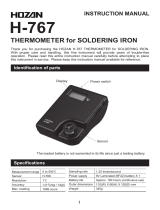
Model F1125, F1130, and F1135 Connector Descriptions
Figure 3.1 Model F1125 Front View
RF IN connector
SMA female connector that connects to signal generator output. The RF power that comes in this
connector is applied equally to the DUT and the power standard. The fact that equal RF power is
applied to both the power standard and the DUT is what allows the determination the calibration
factor of the DUT. There is at least 6 dB of insertion loss in the RF IN path and as much as 10.5
depending on the specific model (see “Specifications” in Chapter I Instrument Description).
TEMP connector
4 pin mini-microphone connector that is used to connect the internal heater to a heater control
circuit found in TEGAM Models 1805B, 1806(A), 1830A, and 1820. RF Power Standards require at
least two hours of warm-up time to reach their operating temperature. A Temperature Control
cable is supplied with the Models F1125, F1130, and F1135.
BIAS VOLTAGE connectors
Binding posts used to connect the thermistor element to a DC Substitution bridge circuit as is
found in the TEGAM Models 1805B, 1806(A), 1830A, and 1804. The bridge operates on the
principal of DC substitution, so only DC voltages and currents are present at these terminals when
connected.
/