
5015 B.U. Bowman Drive Buford, GA 30518 USA Voice: 770-831-8048 Fax: 770-831-8598
Type Acceptance Test Report
Multimode PCS Repeater
FCC Rule Parts: 2, 15 & 24
ACS Report Number: 03-0089-24TA
Manufacturer: EMS Wireless
Model: Link2Cell
Installation Guide

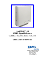
Link2Cell™-19
SOHO Signal Enhancer
Small Office – Home Office SIGNAL ENHANCER
OPERATOR’S MANUAL
2850 Colonnades Court NW
Norcross, GA 30071
Phone: 770-582-0555
Fax: 770-729-0075
Email: www.emswireless.com

Preliminary Document Confidential EMS Wireless
Link2Cell
TM
-19
Manual
2
Disclaimer
Every attempt has been made to make this material complete, accurate, and up-to-date. Users
are cautioned, however, that EMS Wireless reserves the right to make changes without notice
and shall not be responsible for any damages, including consequential, caused by reliance on
the material presented, including, but not limited to, typographical, arithmetical, or listing errors.
Copyright Information
© EMS Wireless
EMS Wireless
Norcross, Georgia

Preliminary Document Confidential EMS Wireless
Link2Cell
TM
-19
Manual
3
WARNINGS, CAUTIONS, AND GENERAL NOTES
This product conforms to FCC Part 15. Changes or modifications not expressly approved
by the party responsible for compliance could void the user's authority to operate the
equipment.
NOTE: This equipment has been tested and found to comply with the limits for a
Class B digital device, pursuant to Part 15 of the FCC Rules. These limits are
designed to provide reasonable protection against harmful interference in a
residential installation. This equipment generates, uses and can radiate radio
frequency energy and, if not installed and used in accordance with the instructions,
may cause harmful interference to radio communications. However, there is no
guarantee that interference will not occur in a particular installation. If this equipment
does cause harmful interference to radio or television reception, which can be
determined by turning the equipment off and on, the user is encouraged to try to
correct the interference by one or more of the following measures:
• Reorient or relocate the receiving antenna.
• Increase the separation between the equipment and receiver.
• Connect the equipment into an outlet on a circuit different from that to
which the receiver is connected.
• Consult the dealer or an experienced radio/TV technician for help.”
In accordance with FCC regulations regarding human exposure to radiofrequency
energy, this device shall be installed such that a minimum separation distance of
20cm is maintained between it and general population.
The antenna(s) used for this transmitter must not be co-located or operating in
conjunction with any other transmitter.
This Class B digital apparatus meets all requirements of the Canadian
Interference Causing Equipment Regulations. Operation is subject to the
following two conditions: (1) this device may not cause harmful interference, and (2)
this device must accept any interference received, including interference that may
cause undesired operation.
Cet appareillage numérique de la classe B répond à toutes les exigences de
l'interférence canadienne causant des règlements d'équipement. L'opération est
sujette aux deux conditions suivantes: (1) ce dispositif peut ne pas causer
l'interférence nocive, et (2) ce dispositif doit accepter n'importe quelle interférence
reçue, y compris l'interférence qui peut causer l'opération peu désirée.

Preliminary Document Confidential EMS Wireless
Link2Cell
TM
-19
Manual
4
Safety Considerations
When installing or using this product, observe all safety precautions during handling and
operation. Failure to comply with the following general safety precautions and with
specific precautions described elsewhere in this manual violates the safety standards of
the design, manufacture, and intended use of this product. EMS Wireless assumes no
liability for the customer's failure to comply with these precautions.
WARNING
WARNING Calls attention to a procedure or practice, which if ignored, may result in
damage to the system or system component. Do not perform any procedure preceded by a
WARNING until described conditions are fully understood and met.
If You Need Help
If you need additional copies of this manual, or have questions about system options, or
need help with installation and using of the system, please contact EMS Wireless’ Sales
Department.
EMS Wireless Sales Dept.
2850 Colonnades Court NW, Norcross, GA 30071
Tel: 770 582 0555 Extension 5310

Preliminary Document Confidential EMS Wireless
Link2Cell
TM
-19
Manual
5
Service
Do not attempt to modify or service any part of this product other than in accordance with
procedures outlined in this Operator's Manual. If the product does not meet its warranted
specifications, or if a problem is encountered that requires service, notify EMS Wireless’
sales department. Service will be rendered according the EMS Wireless’ warranty and
repair policy. The product shall not be returned without contacting EMS Wireless and
obtaining a return authorization number from the Sales department
When returning a product for service, include the following information: Owner, Model
Number, Serial Number, Return Authorization Number (obtained in advance from EMS
Wireless Customer Service Department), service required and/or a description of the
problem encountered.
The EMS Wireless Quality Plan includes product test and inspection operations to verify
the quality and reliability of our products.
EMS Wireless uses every reasonable precaution to ensure that every device meets
published electrical, optical, and mechanical specifications prior to shipment. Customers
are asked to advise their incoming inspection, assembly, and test personnel as to the
precautions required in handling and testing ESD sensitive components. Physical
damage to the external surfaces voids warranty.
These products are covered by the following warranties:
1. General Warranty
EMS Wireless warrants to the original purchaser all standard products sold by
EMS Wireless to be free of defects in material and workmanship for the duration
of the warranty period of one (1) year from date of shipment from EMS Wireless.
During the warranty period, EMS Wireless’ obligation, at our option, is limited to
repair or replacement of any product that EMS Wireless proves to be defective.
This warranty does not apply to any product, which has been subject to
alteration, abuse, improper installation or application, accident, electrical or
environmental over-stress, negligence in use, storage, transportation or handling.
2. Specific Product Warranty Instructions
All EMS Wireless products are manufactured to high quality standards and are
warranted against defects in workmanship, materials and construction, and to no
further extent. Any claim for repair or replacement of a device found to be
defective on incoming inspection by a customer must be made within 30 days of
receipt of the shipment, or within 30 days of discovery of a defect within the
warranty period.
This warranty is the only warranty made by EMS Wireless and is in lieu of all
other warranties, expressed or implied, except as to title, and can be amended
only by a written instrument signed by an officer of EMS Wireless. EMS Wireless
sales agents or representatives are not authorized to make commitments on
warranty returns.
In the event that it is necessary to return any product against the above warranty,
the following procedure shall be followed:

Preliminary Document Confidential EMS Wireless
Link2Cell
TM
-19
Manual
6
a. Return authorization shall be received from the EMS Wireless Customer
Service prior to returning any device. Advise the EMS Wireless Customer
Service of the model, serial number, and the discrepancy. The device
shall then be forwarded to EMS Wireless, transportation prepaid. Devices
returned freight collect or without authorization may not be accepted.
b. Prior to repair, EMS Wireless Customer Service will advise the customer
of EMS Wireless test results and will advise the customer of any charges
for repair (usually for customer caused problems or out-of-warranty
conditions).
If returned devices meet full specifications and do not require repair, or if
non-warranty repairs are not authorized by the customer, the device may
be subject to a standard evaluation charge. Customer approval for the
repair and any associated costs will be the authority to begin the repair at
EMS Wireless. Customer approval is also necessary for any removal of
certain parts, such as connectors, which may be necessary for EMS
Wireless testing or repair.
c. Repaired products are warranted for the balance of the original warranty
period, or at least 90 days from date of shipment.
3. Limitations of Liabilities
EMS Wireless’ liability on any claim of any kind, including negligence, for any
loss or damage arising from, connected with, or resulting from the purchase
order, contract, or quotation, or from the performance or breach thereof, or from
the design, manufacture, sale, delivery, installation, inspection, operation or use
of any equipment covered by or furnished under this contract, shall in no case
exceed the purchase price of the device which gives rise to the claim.
EXCEPT AS EXPRESSLY PROVIDED HEREIN, EMS WIRELESSMAKES NO
WARRANTY OF ANY KIND, EXPRESSED OR IMPLIED, WITH RESPECT TO ANY
GOODS, PARTS AND SERVICES PROVIDED IN CONNECTION WITH THIS
AGREEMENT INCLUDING, BUT NOT LIMITED TO, THE IMPLIED WARRANTIES OF
MERCHANTABILITY AND FITNESS FOR A PARTICULAR PURPOSE. EMS
WIRELESSSHALL NOT BE LIABLE FOR ANY OTHER DAMAGE INCLUDING, BUT
NOT LIMITED TO, INDIRECT, SPECIAL OR CONSEQUENTIAL DAMAGES ARISING
OUT OF OR IN CONNECTION WITH FURNISHING OF GOODS, PARTS AND
SERVICE HEREUNDER, OR THE PERFORMANCE, USE OF, OR INABILITY TO USE
THE GOODS, PARTS AND SERVICE.
EMS Wireless test reports or data indicating mean-time-to-failure, mean-time-
between-failure, or other reliability data are design guides and are not intended to
imply that individual products or samples of products will achieve the same
results. These numbers are to be used as management and engineering tools,
and are not necessarily indicative of expected field operation. These numbers
assume a mature design, good parts, and no degradation of reliability due to
manufacturing procedures and processes.

Preliminary Document Confidential EMS Wireless
Link2Cell
TM
-19
Manual
7
Handling the Link2Cell™ -19
1. Use ESD precautions when dealing with the modules within the Link2Cell™ -19 so that units
are not damaged.
2. Opening the unit voids warranty.
3. Disconnecting any component within the Link2Cell™-19 when powered can damage or destroy
the equipment and will void the warranty.

Preliminary Document Confidential EMS Wireless
Link2Cell
TM
-19
Manual
8
Link2Cell™-19 Manual
Description
The Link2Cell™-19 SOHO, (Small Office-Home Office) Signal Enhancer, is a PCS band, bi-
directional amplifier unit and was designed to provide enhanced RF coverage for wireless
systems in small facilities. Usage includes providing coverage in retail stores, offices,
warehouses, restaurants, homes, etc.
The Link2Cell™-19 is housed in an indoor mountable enclosure, and is powered with a
regulated wall mountable power supply.
The Link2Cell™-19 supports all system protocols including CDMA, GSM/PCS1900 and
TDMA and a single model will cover all licensed 1.9 GHz PCS bands A through F. The
Link2Cell™-19 features Auto set-up, lightweight compact enclosure with internal antennas,
local alarming, and excellent electrical specifications, high reliability with cost effective
pricing.
Functionality
The Link2Cell™-19 is capable of automatically adjusting its own signal gain levels up to the
maximum output power levels. The Link2Cell™-19 detects the downlink output power and
adjusts the level for 2 dBm composite output power and continues to monitor and reset the
gain as required for proper system performance. For example, when CDMA protocol system
is being amplified, there could be an error in set up initially resulting from only pilot sync, and
paging Walsh codes being present on the RF carrier. The Link2Cell™-19 will reduce the
system gain until no signal is received that will exceed the output power setting. This
prevents the Link2Cell™-19 from setting up to a higher in power level than actually desired if
all of the Walsh codes were present. The gain does not continually change to maintain an
output power of 2 dBm AGC (Automatic Gain Control) since this would defeat the benefits
of power control in the service providers system.
The Link2Cell™ has 40 dB of gain control in the uplink and downlink signal paths. This
gain is controlled by a microprocessor that monitors the system operation on a real time basis.
The uplink and downlink attenuators are controlled by the internal microprocessor to adjust
for maximum gain in both paths. The uplink and dowlink signal paths are adjusted to the same
setting by the microprocessor unless the system determines this is not optimum for the units
operation.
Alarming
Alarming monitoring is accomplished in the Link2Cell™ by the microprocessor, which will
detect a failure in gain or a system oscillation. This is indicated to the user by a solid constant

Preliminary Document Confidential EMS Wireless
Link2Cell
TM
-19
Manual
9
Red indicator. User can try recycling the power which will allow the unit to go thru its
automatic set up operation but if the problem persists contact your service provider.
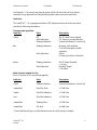
Indicators
The Link2Cell™-19 is equipped with three LED indicators on the end of the unit which
provide the following information:
During normal operation:
Indicator State Description
Green Off No DC Input Power Applied
Solid Indication DC Power on, normal function
Flashing Indication System Initialization, Auto Set Up
Red Flashing Indication Warning, fault condition
(Unit will reset gain to stable
operation)
Solid Indication Alarm
(Contact your Service Provider)
Amber Flashing Indication No RF Signal Detected
(<-90 dBm)
Solid Indication Weak RF Signal
(>-85 dBm)
Initial System Automatic Set Up:
(First 2-3 minutes of DC power being applied)
Indicator State Description
Green Flashing Indicator System Initialization, Auto Set Up
Amber/Red Solid On, Both >76 dB Gain
Amber Solid On Indication >73 dB Gain
Red Solid On Indication >70 dB Gain
Amber/Red Flashing Both >67 dB Gain
Amber/Red Off, both <64 dB Gain
*Green Indicator will go to a solid indication once the initial set up is complete.

Preliminary Document Confidential EMS Wireless
Link2Cell
TM
-19
Manual
10
Primary Power
The Link2Cell™ Unit operates on 9 VDC input power @ 1 Amp. This is supplied with a
regulated wall mount supply, which is UL, and CSA listed. These are available to operate on
AC input voltage of 115 VAC.
Donor/Server Antenna
Internal donor and server antenna are each 13 dB nominal gain. The donor antenna must be
orientated to point in the direction of the Service Providers cell site location. Beam width of
the antennas is approximately 60 degrees wide so it is necessary for the antenna to point
toward the cell site. The indicators will provide a reference of the strongest RF power strength
when the antenna is located in the optimum location.

Preliminary Document Confidential EMS Wireless
Link2Cell
TM
-19
Manual
11
Installation:
Note 1: The user is cautioned that modification or changes to this device not expressly approved by the party
responsible for compliance could void the user’s authority to operate this equipment.
Note 2: Manufacturer’s rated composite output power, individual channel power will vary depending on the
number of channels and distance from each cell site being received
Note 3: This device complies with Part 15 of the FCC Rules. Operation is subject to the condition that this
device does not cause harmful interference.
Introduction
Link2Cell™-19 is quick and easy to install, using a set of common tools. This section will
provide the basic steps to performing the installation of Link2Cell™ . Please read
complete instructions before beginning assembly.
Placement of the Unit
Unit must be positioned with the donor antenna facing the direction of the cell site and the
opposite side of the unit with LED indicators facing the intended coverage area. Signal
strength at this location should be adequate to make a call with the subscriber unit for the
SOHO, (Small Office-Home Office) signal enhancer to provide additional coverage and
service in the facility. (See optional mounting configurations in figure 2.)
The signal enhancer provides improved signal performance by amplifying radio frequency
signals being received from the base station and the subscriber unit (mobile phone). The
model Link2Cell™ provides signal enhancement for the entire PCS band only, see the
Link2Cell specifications for details on equipment.
Link2Cell™ is designed to automatically set up its own gain and will improve performance
in most applications as long as a signal is received at the window location. Actual area of
coverage that will be improved will vary depending on the signal level received, and blockage
to the signals in the desired area of coverage. Blockages to RF signals include walls, people,
equipment and furniture, etc. Amount of signal attenuation by each of these blockages will
vary depending upon their size and composition.
If additional area of coverage is required, additional Link2Cell™ units can be cascaded inside
of the facility to provide this. There is a practical limit to the number of signal enhancers that
can be cascaded and provide enhanced system performance. If greater than three total
Link2Cell units are required you should call your system provider for additional solutions
that are available.

Preliminary Document Confidential EMS Wireless
Link2Cell
TM
-19
Manual
12
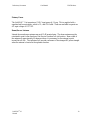
Getting Started:
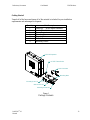
Unpack all of the boxes and insure all of the material is included for your installation
requirements and undamaged in shipment.
Quantity Part Description
1
Link2Cell™ SOHO Signal Enhancer
1 Loctite Thread locker
1 Power Converter
1 Mounting Base
2 Mounting Posts
4 Wall Anchors
4 Mounting Screws
Figure 1
Package Contents
Link2Cell Repeater
Power Converter
Mounting Base
Mounting Posts (2)
Wall Anchors (4)
Mounting Screws (4)
LOCTITE Threadlocker

Preliminary Document Confidential EMS Wireless
Link2Cell
TM
-19
Manual
13
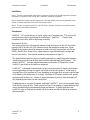
Link2Cell™-19 Unit Orientation & Installation
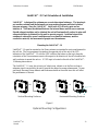
Link2Cell™ is designed for optimum use as an in-door signal enhancer. The housing is
not weather resistant and the automatic set up procedure assumes sufficient isolation
between antennas. Since the Link2Cell™ has a total of 53 dB active gain and an
isolation of 73 dB must be obtained between the internal donor and the server antenna.
Should adequate isolation not be obtained the unit will automatically reduce its gain until
adequate isolation is obtained for the unit to operate properly. Isolation between the
antennas is reduced by several conditions near or around the antennas, metal or
conductive material, and movement of people near the antennas.
Mounting the Link2Cell™-19
Link2Cell™-19 must be mounted so the Donor antenna is orientated to receive and transmit to
the cell site. The Donor antenna is located on the opposite side of the unit of the LED
indicators of the Link2Cell™-19 with the LED’s either at the bottom or the top to keep the
orientation of the Donor antenna correct with respect to the direction of the cell site and which
wall you desire to mount the unit on. 9 VDC input is located on the side of the Link2Cell™-
19 housing shown above.
The Link2Cell™-19 may also sit on top of a book case, cabinet or on the floor as long as
adequate signal is received by the unit to provide the desired coverage enhancement. As was
previously discussed, these cabinets and bookcases should not be metal since this will effect
the performance of the unit.
OR OR
.
Vertical Mounting Surfaces Horizontal Mounting Surfaces
Figure 2
Optional Mounting Configurations
Plug Power Converter
into Unit
Plug Power Converter
into 110V Outlet

Preliminary Document Confidential EMS Wireless
Link2Cell
TM
-19
Manual
14
-Select the window that provides the strongest signal strength from the cell site to your
portable phone by viewing the number of bars displayed on the face of the phone.
- Select the location in the window that provides the strongest signal strength from the
cell site to your portable phone which will indicate how to position the Link2Cell™
(donor antenna) signal enhancer unit
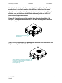
-Remove the 2 protective caps of the mounting holes from the selected side of the
Link2Cell™, taking into consideration the 3 LED’s must be facing you or the desired
area of coverage.
-Apply Loctite to the threads of the mounting posts and install (hand tighten only) into
the open mounting holes of Link2Cell™ unit.
Remove Protective Caps from
Mounting Holes
Apply LOCTITE to Threads of Mounting Posts
in Accordance with Manufacturers Instructions
and Install into Link2Cell Unit.
Hand-Tighten Only

Preliminary Document Confidential EMS Wireless
Link2Cell
TM
-19
Manual
15
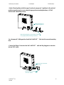
-Attach Mounting Base (with the open U potion in an upward ? position) to the selected
position mounting surface area using the appropriate mounting hardware, (4 Wall
anchors and 4 mounting screws).
-In a downward ? sliding motion, hook the Link2Cell™ Unit onto the secured mounting
base.
-Connect the Power Converter into the Link2Cell™ unit and the plug power converter
into an 110V outlet.
Attach Mounting Base to Mounting Surface
Using Appropriate Mounting Hardware
Slide Link2Cell Unit
into Mounting Base
Plug Power Converter
into Unit
Plug Power Converter
into 110V Outlet

Preliminary Document Confidential EMS Wireless
Link2Cell
TM
-19
Manual
16
IMPORTANT: Before performing any maintenance or changing the position or location of
the unit, make sure power plug is removed from the 110 AC wall socket. Once the unit is
repositioned, the power should be plugged into the 110 wall socket, this will insure the unit is
set to maximum gain and performance.
System Set Up Instructions:
-After installing unit, apply power and Link2Cell™ unit will automatically set up. The
system initialization will require 1 – 2 minutes for setup completion.
-Note: Since the Link2Cell™ is a broadband unit, it will improve the service for all
system providers with cell sites in the direction the donor antenna is positioned.
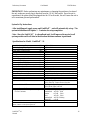
Specifications for Model: Link2Cell™-19
Downlink Operating Frequency, MHz 1930 to 1990
Uplink Operating Frequency, MHz 1850 to 1910
Downlink EIRP Transmit Power dBm 15
Uplink EIRP Transmit Power dBm 28
System Gain dB 40 to 79
Gain Flatness dB
+/− 2
Noise Figure dB
≤ 6
Spurious Output @ Rated Power
FCC Regulations dB
≤ -13
@Fc +/− 885 KHz (CDMA only) dBc ≤ 45
@Fc +/− 1.25 MHz dBc ≤ 26
2 tone @ -1 dBm each, DL dBc
≤ 60
1 dB Compression dBm UL 22, DL 22
IP3 dBm UL 41, DL 41
Operating Temperature, degrees C 0° to +50°
Power Source: (115 VAC) 9 VDC@ 1 amp, External AC to DC
Mechanical Dimensions, H x W x D, inches 14.25 x 14.25 x 6.0
MTBF hours 80,000
Indicators, Green LED Solid, Normal Operation
Red LED Flashing, Signal Overdrive
Solid, Auto Off, Contact Service Provider
Yellow LED
Flashing, No Signal Detected, ≤ 90 dB
Solid, Weak Signal, ≤ 85 dB
Automatic System Set Up Upon Power Up
System Gain Indications upon Power Up
For first 3 minutes
Green, Flashing during set up
Amber/Red ≥ 76 dB Solid
Amber ≥ 73 dB Solid
Red ≥ 70 dB Solid
Amber/Red ≥ 67 dB Flashing
Both OFF = 64 dB
Certifications, FCC, UL, CSA
*Meets or exceeds the EIA/TIA system requirements for
CDMA, TDMA or GSM system protocols.

Preliminary Document Confidential EMS Wireless
Link2Cell
TM
-19
Manual
17
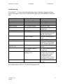
Trouble Shooting:
The Link2Cell™-19 has no field replaceable parts; repair is limited to improper mounting
location with respect to the cell site, insufficient RF signal levels, and installation or defective
units.
Problem Check Corrective Action
No Power Power Source Reconnect or repair
Power Source OK Replace Unit
Alarm Indication Recycle AC Power
No change Replace Unit
Amber Flashing No RF signal Detected Recycle AC Power
No Change Check Antenna alignment
with cell site
No Change Replace Unit
Amber Solid Indicator Weak RF Signal New Installation, Check
Antenna alignment with cell
site and recycle power
Weak RF Signal Previously working, recycle
power.
No Change Replace Unit
Green Flashing Indication Unit is in initial system
initialization, if still flashing
after 5 minutes replace unit
No signal improvement to
subscriber unit
Recycle power to unit Watch indicators for gain
settings.
Gain Settings, Amber or
Amber/red
OK, check antenna alignment
with cell site.
Red, amber/red solid or
flashing, or off
Insufficient isolation between
antennas in the unit possibly.
Move unit and try again.
Unit operation can be
effected if placed to close to
metal objects or equipment.
No Change Consult your Service
Provider
For Customer Service Call, Tel: 770 583-0555 Extension 5310
-
 1
1
-
 2
2
-
 3
3
-
 4
4
-
 5
5
-
 6
6
-
 7
7
-
 8
8
-
 9
9
-
 10
10
-
 11
11
-
 12
12
-
 13
13
-
 14
14
-
 15
15
-
 16
16
-
 17
17
-
 18
18


EMS Link2Cell-19 User manual
- Type
- User manual
- This manual is also suitable for
Ask a question and I''ll find the answer in the document
Finding information in a document is now easier with AI
Related papers
Other documents
-
Okayo AB-771T User manual
-
AnyTone AT-7100 User manual
-
PowerTec Soho Mobile repeater User manual
-
Panasonic KXTG7743 Operating instructions
-
-
-
Panasonic KX-TGH264 User manual
-
Panasonic KXTG7845 Operating instructions
-
-