Page is loading ...

Adeunis
283 rue Louis Néel - Parc Technologique Pré Roux
38920 CROLLES - France
www.adeunis.com
LoRaWAN MODBUS MASTER
Transceiver Modbus Interface
User Guide
Version 1.0.0

FR
EN
LoRaWAN MODBUS MASTER - User guide version V1.0.0
2
Page of 22
NEW DOCUMENTATION
USER GUIDE
TECHNICAL REFER-
ENCE MANUAL
INSTALLATION GUIDE
• Dedicated to a product
• Cautions & electrical warnings
• Declaration of conformity
• Product functionalities and modes
• Casing dimensions
• Characteristics (casing and electrical)
• LED explanations
• Specific wiring on terminal blocks
• Dedicated to a product
• Registers content
• Frame explanations (uplink and downlink)
• For all adeunis® products
• Configuration of the products
• Installation and fixing
• Start-up of the products
• Opening and closing the case
• Replace battery
ENGLISH

FR
EN
LoRaWAN MODBUS MASTER - User guide version V1.0.0
3
Page of 22
Préambule / Preamble / Präambel / Preambolo / Preámbulo
• Ce guide décrit les fonctionnalités du produit adeunis®. Il explique les modes de fonctionnement du produit et
la manière de le confi gurer.
• This guide describes the functionalities of the product adeunis®. It explains its functionnments and how to
confi gure it.
• Dieser Leitfaden beschreibt die Funktionalität des Produktes adeunis®. Er erklärt die Betriebsfunktionen des
Produktes und die Art und Weise, um es zu konfi gurieren.
• Questa guida descrive la funzionalità del prodotto adeunis®. Questo spiega come funziona il prodotto e come
confi gurarlo.
• Esta guía describe las funcionalidades del producto adeunis®. En él se explica los modos de funcionamiento
del producto y cómo confi gurarlo.
• Aucun extrait de ce document ne pourra être reproduit ou transmis (sous format électronique ou papier, ou
par photocopie) sans l’accord d’adeunis®. Ce document pourra être modifi é sans préavis. Toutes les marques
citées dans ce guide font l’objet d’un droit de propriété intellectuelle.
• No part of this document may be reproduced or transmitted (in electronic or paper, or photocopying) without
the agreement adeunis®. This document may be changed without notice. All trademarks mentioned in this
guide are the subject of intellectual property rights. adeunis®.
• Kein Teil dieses Dokuments darf reproduziert oder übertragen werden (in elektronischer oder Papierform oder
Fotokopie) ohne die Zustimmung adeunis®. Dieses Dokument darf ohne vorherige Ankündigung geändert wer-
den. Alle Marken in diesem Handbuch erwähnt werden, sind Gegenstand des geistigen Eigentums.
• Nessuna parte di questo documento può essere riprodotta o trasmessa (in fotocopie elettronico o cartaceo, o),
senza il consenso adeunis®. Questo documento può essere modifi cato senza preavviso. Tutti i marchi citati in
questa guida sono oggetto di diritti di proprietà intellettuale.
• Ninguna parte de este documento puede ser reproducida o transmitida (en fotocopias electrónico o en papel,
o) sin el acuerdo adeunis®. Este documento puede ser modifi cada sin previo aviso. Todas las marcas comer-
ciales mencionadas en esta guía son el tema de los derechos de propiedad intelectual.
Adeunis
283, rue Louis Néel
38920 Crolles
France
Web www.adeunis.com

FR
EN
LoRaWAN MODBUS MASTER - User guide version V1.0.0
4
Page of 22
TABLE OF CONTENT
NEW DOCUMENTATION 2
PRODUCTS AND REGULATORY INFORMATION 5
1. PRODUCT PRESENTATION 10
1.1. General description 10
1.2. Dimensions 11
1.3. Electronic board 11
1.4. Technical Specifications 12
1.4.1 General characteristics 12
1.4.2 Characteristics of physical interfaces 12
2. PRODUCT OPERATION 13
2.1. Global Operation 13
2.1.1 PARK mode 13
2.1.2 COMMAND mode 13
2.1.3 PRODUCTION mode 13
2.2. Application operation 14
2.2.1 Periodic transmission 14
2.2.2 Transmission on exceeding of the threshold 15
2.2.3 Transmission on exceeding of the threshold, with alarm repetition 17
2.2.4 Transmission of a daily Keep Alive frame 18
2.2.5 Transmission of the response frame following a «reading register slave» request 18
2.2.6 Transmission of the acknowledgment following a “write in a slave register” request 18
2.3. Operation of the LEDs 19
3. REGISTERS AND FRAMES 20
4. CONFIGURATION AND INSTALLATION 20
4.1. Configuration and installation of the transmitter 20
4.2. Modbus specificities in the IoT Configurator 20
4.2.1 Test Modbus read, test reading into slave registers 20
4.2.2 Test Modbus write, test the writing into a slave register 20
4.3. Cables description 21
4.4. Link configuration 21
4.5. 2-wire RS485 example of wiring 21
4.6. RS232 example of wiring 22
4.7. LED an help to install 22
5. DOCUMENT HISTORY 22

FR
EN
LoRaWAN MODBUS MASTER - User guide version V1.0.0
5
Page of 22
PRODUCTS AND REGULATORY INFORMATION
Document Information
Title
LoRaWAN MODBUS MASTER - User Guide
Sub-title
/
Document type
User Guide
Version
1.0.0
This document applies to the following products :
Nom Référence Version firmware
LoRaWAN MODBUS MASTER
ARF8240JA Version RTU : V1.7.1
Version APP : V2.0.0
DISCLAIMER
This document and the use of any information contained therein, is subject to the acceptance of the adeunis®
terms and conditions. They can be downloaded from www.adeunis.com.
adeunis® makes no warranties based on the accuracy or completeness of the contents of this document and
reserves the right to make changes to specifi cations and product descriptions at any time without notice.
adeunis® reserves all rights to this document and the information contained herein. Reproduction, use or disclo-
sure to third parties without express permission is strictly prohibited. Copyright © 2016, adeunis®.
adeunis® is a registered trademark in the EU and other countries.
TECHNICAL SUPPORT
Website
Our website contains a lot of useful information: information on modules and wireless modems, user guides, and
confi guration software and technical documents which can be accessed 24 hours a day.
E-mail
If you have technical problems or cannot fi nd the required information in the provided documents, contact our
Technical Support on our website, section « Technical Support ». This ensures that your request will be processed
as soon as possible.
Helpful Information when Contacting Technical Support
When contacting Technical Support, please have the following information ready:
• Product type
• Firmware version (for example V1.0)
• A clear description of your question or the problem
• A short description of the application

FR
EN
LoRaWAN MODBUS MASTER - User guide version V1.0.0
6
Page of 22
Declaration of conformity - New Zealand
Manufacturer’s name : adeunis.
Manufacturer’s address : Parc Technologique PRE ROUX
283 rue Louis NEEL
38920 CROLLES
Country: FRANCE
Authorized representative in Australia Direct Control Limited
E3441
Address : Wellesley Street,
1141 Auckland
Country: NEW ZEALAND
Authorized representative in Australia Go Wireless NZ Ltd
E678
Address : 1 Kingsford Smith Drive
Unit 5, 7440 Rangiora (North Canterbury)
Country: NEW ZEALAND
Certify and declare under our sole responsibility that the following apparatus:
Description : MODBUS Wireless transceiver in 915-928MHz band
Manufacturer: adeunis
Identication: ARF8240J
Conforms with the essential requirements for Australia market:
Harmonized Standards :
• IEC 62368-1(safety)
• AS/NZS 4268:2017
Name and position of person binding the manufacturer Emmanuel MONNET
or his authorized representative: Certication Manager- adeunis

FR
EN
LoRaWAN MODBUS MASTER - User guide version V1.0.0
7
Page of 22
INTRODUCTION
All rights to this manual are the exclusive property of adeunis®. All rights reserved. Copying this manual (wit-
hout written permission from the owner) via printing, copying, recording or by any other means, translating this
manual (in full or partially) into any other language, including all programming languages, using any electrical,
mechanical, magnetic or optical devices, manually or any by other methods, is prohibited.
adeunis® reserves the right to change the technical specifi cations or functions of its products, or to cease manu-
facturing any of its products, or to cease technical support for one of its products without notice in writing and
urges its customers to make sure that the information they have is valid.
adeunis® confi guration software and programs are available free of charge in a non-modifi able version. adeu-
nis® can make no guarantees, including guarantees concerning suitability and applicability for a certain type
of application. Under no circumstances can the manufacturer, or the distributor of an adeunis® program, be
held liable for any damage caused by the use of the aforesaid program. Program names, as well as all copyright
relating to programs, are the exclusive property of adeunis®. Any transfer, granting of licences to a third party,
leasing, hire, transport, copying, editing, translation, modifi cation into another programming language or reverse
engineering are prohibited without adeunis®’s prior written authorisation and consent.
Adeunis
283, rue Louis Néel
38920 Crolles
France
Web
www.adeunis.com

FR
EN
LoRaWAN MODBUS MASTER - User guide version V1.0.0
8
Page of 22
ENVIRONMENTAL RECOMMENDATIONS
All superfl uous packaging materials have been eliminated. We have done everything possible to make it easy to
separate the packaging into three types of materials: cardboard (box), expanded polystyrene (fi ller material)
and polyethylene (packets, foam protective sheets). Your device is composed of materials that can be recycled
and reused if it is dismantled by a specialist company. Please observe local regulations concerning the manner in
which waste packaging material, used batteries and your obsolete equipment are disposed of.
WARNINGS
Valid for products indicated in the declaration of conformity
Read the instructions in the manual.
The safety of this product is only guaranteed when it is used in accordance with its purpose. Maintenance
should only be carried out by qualifi ed persons.
Risk of explosion if the battery is removed with an incorrect type. Contact Adeunis for more information if
needed.
Risk of explosion if the battery is replaced by an incorrect type
Please note: Do not install the equipment close to a heat source or in damp conditions.
Please note: When the equipment is open, do not carry out any operations other than the ones set out in this
document.
Please note: Do not open the product as there is a risk of electrical shock.
Please note: For your own safety, you must ensure that the equipment is switched off before carrying out
any work on it.
Please note: For your own safety, the power supply circuit must be SELV (Safety Extra Low Voltage) and
must be from limited power sources.
Please note: When the aerial is installed outside, it is essential to connect the cable screen to the buil-
ding’s earth. We recommend using lightning protection. The protection kit chosen must permit the coaxial cable
to be earthed (eg: coaxial lightning arrester with earthing of the cable at diff erent places on the aerial at the base
of pylons and at the entrance, or just before entering the premises).
The product must be equipped with a switching mechanism so that the power can be cut. This must be close to
the equipment. Any electrical connection of the product must be equipped with a protection device against vol-
tage spikes and short-circuits.
Please note: the equipment is not intended for the use by a child.

FR
EN
LoRaWAN MODBUS MASTER - User guide version V1.0.0
9
Page of 22
RECOMMANDATIONS REGARDING USE
• Before using the system, check that the power supply voltage shown in the user manual corresponds to your
supply. If it doesn’t, please consult your supplier.
• Place the device against a fl at, fi rm and stable surface.
•
The device must be installed in a location that is suffi ciently ventilated so that there is no risk of internal hea-
ting and it must not be covered with objects such as newspapers, cloths, curtains, etc.
• The device’s aerial must be free and at least 10 cm away from any conducting material.
• The device must never be exposed to heat sources such as heating equipment.
• Do not place the device close to objects with naked fl ames such as lit candles, blowtorches, etc.
• The device must not be exposed to harsh chemical agents or solvents likely to damage the plastic or corrode
the metal parts.
DISPOSAL OF WASTE BY USERS IN PRIVATE HOUSEHOLDS WITHIN THE EURO-
PEAN UNION
This symbol on the product or on its packaging indicates that this product must not be disposed of with your
other household waste. Instead, it is your responsibility to dispose of your waste by taking it to a collection point
designated for the recycling of electrical and electronic appliances. Separate collection and recycling of your waste
at the time of disposal will contribute to conserving natural resources and guarantee recycling that respects the
environment and human health. For further information concerning your nearest recycling centre, please contact
your nearest local authority/town hall offi ces, your household waste collection company or the shop where you
bought the product
This symbol on the devode or its packaging means the use of a DC voltage.
Warning: If the charger is used with any other batteries or products whatsoever, there is a risk of an ex-
plosion. After use, the batteries must be disposed of at an appropriate recycling centre. They must not be thrown
away to degrade in the environment. When batteries are replaced, the device must be corectly implemented.
Warning for Switzerland : the annex 4.10 of SR 814.013 Standad must be applied for batteries.

FR
EN
LoRaWAN MODBUS MASTER - User guide version V1.0.0
10
Page of 22
1. PRODUCT PRESENTATION
Description:
• The adeunis® LoRaWAN MODBUS MASTER is a ready-to-use radio transmitter with a MODBUS interface
• This product meets the needs of users to communicate with one or several MODBUS slaves and transmit their information via a LoRaWAN
network.
• The product use the Remote Terminal Unit (RTU) Modbus protocol to communicate with the slaves.
• The frame of the product can contain 24 registers (of 2 bytes) maximum per periodic frame. These registers can be distributed between the
monitored slaves (20 slaves maximum) knowing that for each slave 15 registers can be configured per frame.
• The product transmits the data from the slaves periodically through one or several frames (up to 6) with the same or different
periods of transmission.
• The product transmits the data from slave either periodically or in an event-related way based on high or low thresholds.
• The product is able to read or write in the registers of a slave through the network.
• The configuration of the transmitter is accessible by the user via a micro-USB port or remotely via the LoRaWAN network, allowing in
particular a choice of modes of transmission, periodicity or triggering thresholds.
• The LoRaWAN MODBUS MASTER is powered by an external power supply (not included).
• The product is able to provide and control the power supply for a slave.
IMPORTANT NOTE: The LoRaWAN MODBUS MASTER is delivered by default with OTAA configuration, allowing the user to declare his/her
product to a LoRaWAN operator.
Composition of the package
The product is supplied in a cardboard box containing the following items:
top casing, electronic card, casing base plate,
Cable gland, 3 gland seals, 2 CBLZ 2.2 x 19mm screws, 2 Fischer SX4 plugs
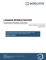
1.1. General description
105
90
27
50
105
90
27
50
2 holes for passing
collars through
Rail-DIN unlocking
lever
4 fastening holes
Cables outlet
packing gland
Casing base
Casing base detail
Antenna

FR
EN
LoRaWAN MODBUS MASTER - User guide version V1.0.0
11
Page of 22
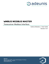
1.2. Dimensions
Values in millimeters
105
90
27
50
105
90
27
50
105
90
27
50
Internal antenna
1.3. Electronic board
Switch for configuration
105
90
27
50
105
90
27
50
USB port for product
configuration
RF module
LoRaWAN protocol

FR
EN
LoRaWAN MODBUS MASTER - User guide version V1.0.0
12
Page of 22
1.4. Technical Specifications
1.4.1 General characteristics
Parameters VALUE
Supply DC 6-30V
Maximum supply 90mA
Working temperature -25°C / +70°C
Dimensions 105 x 50 x 27mm
Weight 70g
Casing IP 67
MODBUS protocol used Remote Terminal Unit (RTU)
LoRaWAN zone AS920-923
LoRaWAN specification 1.0.2
Transmitting power 14 dBm
Applicative port of the product (downlink) 1
1.4.2 Characteristics of physical interfaces
Parameters VALUE
Cables length 70cm
Number of wires on power cable 2 wires: +V, GND
External power supply voltage DC 6-30V
Number of wires of sensor (slave) cable 6 wires : RTS/TX-, CTS/RX-, RX/RX+, TX/TX+, Ground, Sensor power
supply
RS232 3 useful signals: RX, TX, Ground (RTS and CTS are not handled)
Voltages shown are common mode voltages.
Voltages on inputs/outputs: +/-5V typ | +/-15V max
RS485 5 useful signals : TX-, RX-, RX+, TX+, Ground
Voltages shown are common mode voltages.
The product is master of the link: the slave must not inject voltage on
the bus!
Voltages on inputs/outputs: +/-1.5V typ (3V differential)
Polarization resistors: 560 Ohms
Termination resistor: 120 Ohms
Sensor (slave) power supply = External power supply voltage
Current max returned to the sensor (provided that the power supply
used can provide this current)
500 mA

FR
EN
LoRaWAN MODBUS MASTER - User guide version V1.0.0
13
Page of 22
2. PRODUCT OPERATION
2.1. Global Operation
Important: adeunis® use the most significant byte first format.
The product has several operating modes:
2.1.1 PARK mode
The product is delivered in PARK mode, it is in standby mode and its consumption is minimal. To switch the product out of the Park* Mode pass
a magnet across it for a duration higher than 6 seconds. The green LED illuminates to indicate the detection of the magnet and then flashes
quickly during the product starting phase.
The device then sends its configuration and data frames.
2.1.2 COMMAND mode
This mode allows the user to configure the registers of the product.
To enter this mode, connect a cable to the micro-USB port of the product and choose to use the IoT Configurator or to use the command mode
by an AT command. The exit of the COMMAND mode can be done with an ATO command or unplugging the USB cable.
The product will turn into the configured mode, PARK or PRODUCTION.
2.1.3 PRODUCTION mode
This mode allows the user to operate the product in its final use.
PARK MODE
COMMAND MODE
Command send-
ing by serial link
Presence of a magnet
on the product >6s
PRODUCTION MODE

FR
EN
LoRaWAN MODBUS MASTER - User guide version V1.0.0
14
Page of 22
2.2. Application operation
2.2.1 Periodic transmission
The product allows the measurement and the periodic transmission of the VALUE s of the sensors according to the following diagram:
Product in standby
Read slave(s) regis-
ter(s)
Send periodic frame
Period
reached?
YES
Example:
Register VALUE encoding VALUE Result
S301 Decimal 360 Periodic mode with a period of 360x10s = 3600 seconds =
1 hour
S322 Decimal 200 The supply time of the external load (slave) before the
Modbus request is 200 x 100 = 20 000ms ie 20s
S330 Hexadecimal 0x01151812 Periodic data 1 configuration:
• Slave address = 0x01
• First register address = 0x1518
• Periodic frame chosen = Periodic frame 1
• Modbus registers type : holding registers
• Number of registers = 2
S331 Hexadecimal 0x570ED814 Periodic data 1 configuration:
• Slave address = 0x57
• First register address = 0x0ED8
• Periodic frame chosen = Periodic frame 1
• Modbus registers type : input registers
• Number of registers = 4
No
The product can send up to 6 different periodic frames with different transmission
period configurable :
• Frame 0x44 being frame 1
• Frame 0x5F being frame 2
• Frame 0x60 being frame 3
• Frame 0x61 being frame 4
• Frame 0x62 being frame 5
• Frame 0x63 being frame 6
The parameters associated with this mode of operation are:
• Transmission period (register S301 or S323, S324, S325, S326, S327 depending on
the concerned frame)
• External load supply time before the Modbus request (register S322)
• Definition of periodic data (registers S330 to S349)

FR
EN
LoRaWAN MODBUS MASTER - User guide version V1.0.0
15
Page of 22
2.2.2 Transmission on exceeding of the threshold
The product allows the reading of MODBUS slave registers and the comparison of these data with thresholds (top and bottom) in order to trans-
mit overflow information according to the following diagram:
Send frame 0x45
Period
reached?
VALUE >
low thresh-
old +
hysteresis
?
VALUE
<high
threshold -
hysteresis
?
VALUE <
low thresh-
old
VALUE >
high thresh-
old
Low alert
not en-
abled?
High alert
not en-
abled?
Low alarm enablingHigh alarm disabling Low alarm enablingHigh alarm enabling
Read slave register(s)
Product in standby
NO
NO
NO
NO
NONO
NO
YES
YES
YES
YES YES
YES
YES

FR
EN
LoRaWAN MODBUS MASTER - User guide version V1.0.0
16
Page of 22
There will be as many alarm frames transmitted as VALUE s read on the slave registers exceeding the configured thresholds.
The settings associated with this mode of operation are:
• Acquisition period (register S320)
• Supply time of the external load (slave) before the Modbus request (register 322)
• Alarms configuration (registers S350, 355, 360, 365, 370, 375, 380, 385, 390, 395).
• High threshold alarms (registers S351, 356, 361, 366, 371, 376, 381, 386, 391, 396).
• Hysteresis of high threshold alarms (registers S352, 357, 362, 367, 372, 377, 382, 387, 392, 397).
• Low threshold alarms (registers S353, 358, 363, 368, 373, 378, 383, 388, 393, 398).
• Hysteresis of low threshold alarms (registers S354, 359, 364, 369, 374, 379, 384, 389, 394, 399).
The complete list of registers can be found in paragraph 3.4.
E.g.:
Register VALUE encoding VALUE Result
S320 Decimal 360 Periodic mode with a period of 360x10s = 3 600 seconds = 1hour
S322 Decimal 200 The supply time of the external load (slave) before the Modbus request is
200 x100ms= 20 000ms ie 20s
S350 Hexadecimal 0x0A106827 Alarm 1 configuration:
• Slave address = 0x0A
• First register address = 0x1068
• Data type : 32-bit unsigned integer (bits 4 to 6 = 2)
• Modbus register type: input registers (bit 2 = 1)
• Active thresholds: low and high (bits 0 to 1 = 3)
S351 Hexadecimal 0x00124F80 High threshold of alarm 1 is 1,200,000 (decimal)
S352 Hexadecimal 0x2710 Hysteresis of high threshold of alarm 1 is 10,000 (decimal)
S353 Hexadecimal 0x00061A80 Low threshold of alarm 1 is 400,000 (decimal)
S354 Hexadecimal 0x2710 Hysteresis of low threshold of alarm 1 is 10,000 (decimal)
IMPORTANT : alarms and thresholds are set to a maximum of 4 bytes (ie 2 maximum Modbus registers).
For a value defined on one register, the user can choose the data type between unsigned or signed 16-bit integer. For a value defined on 2
registers, the user can choose the type of data between: unsigned 32-bit integer or signed 32-bit integer or unsigned 32-bit integer (word swap)
or signed 32-bit integer (word swap).

FR
EN
LoRaWAN MODBUS MASTER - User guide version V1.0.0
17
Page of 22
2.2.3 Transmission on exceeding of the threshold, with alarm repetition
The product sends alarm frame on exceeding thresholds and to repeat this alarm regarding a configurable period (register S320 x S329) while
the alarm is still active.
Product in standby
Send frame 0x45*
No
Slave(s) register(s)
reading
Yes
Period
reached
?
Threshold
overpassed
?
No
Alarm repeti-
tion activated
?
No
Repetition frame 0x45
every S320XS329
Send frame 0x45*
Turn to normal
?
No
Yes
Yes
Yes
There will be as many alarm frames transmitted as VALUE s read on the slave registers
exceeding the configured thresholds.
The settings associated with this mode of operation are:
• Acquisition period (register S320)
• Supply time of the external load (slave) before the Modbus request (register 322)
• Alarms configuration (registers S350, 355, 360, 365, 370, 375, 380, 385, 390, 395).
• High threshold alarms (registers S351, 356, 361, 366, 371, 376, 381, 386, 391, 396).
• Hysteresis of high threshold alarms (registers S352, 357, 362, 367, 372, 377, 382,
387, 392, 397).
• Low threshold alarms (registers S353, 358, 363, 368, 373, 378, 383, 388, 393, 398).
• Hysteresis of low threshold alarms (registers S354, 359, 364, 369, 374, 379, 384, 389,
394, 399).
• Alarm repetition (register S329)
E.g.:
Register Encoding VALUE Result
S320 Decimal 360 Periodic mode with a period of 360x10s = 3
600 seconds = 1hour
S322 Decimal 200 The supply time of the external load (slave)
before the Modbus request is 200 x100ms=
20 000ms ie 20s
S350 Hexadecimal 0x0A106827 Alarm 1 configuration:
• Slave address = 0x0A
• First register address = 0x1068
• Data type : 32-bit unsigned integer (bits
4 to 6 = 2)
• Modbus register type: input registers (bit
2 = 1)
• Active thresholds: low and high (bits 0 to
1 = 3)
S351 Hexadecimal 0x00124F80 High threshold of alarm 1 is 1,200,000
(decimal)
S352 Hexadecimal 0x2710 Hysteresis of high threshold of alarm 1 is
10,000 (decimal)
S353 Hexadecimal 0x00061A80 Low threshold of alarm 1 is 400,000 (decimal)
S354 Hexadecimal 0x2710 Hysteresis of low threshold of alarm 1 is
10,000 (decimal)
IMPORTANT : alarms and thresholds are set to a maximum of 4 bytes (ie 2 maximum
Modbus registers).
For a value defined on one register, the user can choose the data type between unsigned
or signed 16-bit integer. For a value defined on 2 registers, the user can choose the type of
data between: unsigned 32-bit integer or signed 32-bit integer or unsigned 32-bit integer
(word swap) or signed 32-bit integer (word swap).
*The status byte «state of the alarm» inform you about if the alarm is active or not. This
information enables you to dissociate a 0x45 frame when the alarm is active or still active
from a frame 0x45 that informs you that the alarm is deactivated («back to normal»).

FR
EN
LoRaWAN MODBUS MASTER - User guide version V1.0.0
18
Page of 22
The settings associated with this mode of operation are:
• The setting of the period of transmission of the Keep Alive frame (register 300).
E.g.:
Register Encoding VALUE Result
S300 Decimal 8640 The Keep Alive frame is sent every:
8640 x10s= 24h (once per day)
Product in standby
Send frame 0X30
Period
reached?
Yes
No
2.2.4 Transmission of a daily Keep Alive frame
If the product has no periodic data configured, a Keep Alive frame (0x30) is transmitted regu-
larly according to the diagram.
2.2.5 Transmission of the response frame following a «reading register slave» request
This frame is sent in response to a downlink request to read registers in a Modbus slave (0x05).
Reception of
a 0x05 frame
Send frame 0X5E
Reading of the
concerned register in
the slave
If the request is false or there is an error during reading, this frame will be empty.
2.2.6 Transmission of the acknowledgment following a “write in a slave register” request
This frame is sent following the reception of a downlink frame (0x08) to write into the register of a Modbus slave. This frame contains the infor-
mation about the status of the request (success, modbus error, invalid request error).
Reception of a
0x08 frame
Envoi trame 0X2F
Writing into the
concerned register of
the slave

FR
EN
LoRaWAN MODBUS MASTER - User guide version V1.0.0
19
Page of 22
2.3. Operation of the LEDs
Mode LED red state LED green state
Product in Park mode OFF OFF
Magnet detection process (1 to 6 seconds) OFF ON from detection of the magnet up to a
maximum of 1 second
Product start (after detection of the magnet) OFF Rapid flashing 6 cycles, 100 ms ON / 100
ms OFF
Joining process (Lora product) During the JOIN phase: flashing: 50ms on / 1
s off
If the JOIN phase is complete (JOIN accept):
flashing: 50ms on / 50ms Off (6x)
During the JOIN phase: flashing: 50ms on /
1 s off (just after the red LED)
If JOIN phase is complete (JOIN accept):
flashing: 50ms on / 50ms off (just before the
red LED)
Detection of the good communication
between the product Modbus and slaves
10 seconds ON if a default is detected 10 seconds ON if no default detected
Switching to the Command mode Continuously lit Continuously lit
Product faulty (return to factory) Fixed ON

FR
EN
LoRaWAN MODBUS MASTER - User guide version V1.0.0
20
Page of 22
3. REGISTERS AND FRAMES
To know the content of all the registers and for each frame of the product (uplink or downlink) please refer to the TECHNICAL REFERENCE
MANUAL of the LoRaWAN MODBUS MASTER, available on the dedicated product page: https://www.adeunis.com/en/produit/modbus-inter-
face-for-modbus-slaves/
4. CONFIGURATION AND INSTALLATION
4.1. Configuration and installation of the transmitter
To configure the product locally, it is advised to use the IoT Configurator, an android and windows application created by adeunis.
- Google Play : https://play.google.com/store/apps/details?id=com.adeunis.IoTConfiguratorApp
- Windows 10: https://www.adeunis.com/en/downloads/
The product can be configured locally or remotely through the network sending it specific downlink frames. To know which frame use or the
format of each frame, please refer to the TECHNICAL REFERENCE MANUAL of the LoRaWAN MODBUS MASTER, available on the dedicated
product page: https://www.adeunis.com/en/produit/modbus-interface-for-modbus-slaves/
If you want to configure your product through AT command or know how to install your product, refer to the INSTALLATION GUIDE adeunis®.
4.2. Modbus specificities in the IoT Configurator
4.2.1 Test Modbus read, test reading into slave registers
To help to configure or install the MODBUS product, a function to test the reading of a slave has been integrated into the advanced mode of the
IoT Configurator.
Before having wired the product to one or several slaves, it is possible to test the read-
ing into registers of a slave completing the following fields :
• Baud Rate
• Parity
• Stop bits
• Slave address
• First register address
• Number of registers
• Type of registers (holding or input)
The product will test the link and the reading into registers and will show you the
response from the slave.
This function enables you to confirm a configuration before to implement it into the product and switch it to PRODUCTION mode.
4.2.2 Test Modbus write, test the writing into a slave register
To help to configure or install the MODBUS product, a function to test writing into the register of a slave has been integrated into the advanced
mode of the IoT Configurator.
Before having wired the product to one pr several slaves, it is possible to test the
writing function of the product completing the following fields:
• Baud Rate
• Parity
• Stop bit
• Slave address
• Register address
• Value to write into the register
The product will test the link and the writing into the concerned register and will show
you the response from the slave.
This function enables you to confirm the link between the device and the slave register or to write directly in a slave register.
/