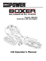
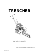
Toro High-Speed Trencher Head, Compact Utility Loaders User manual

Category
Mini tillers
Type
User manual

This manual is also suitable for

Toro High-Speed Trencher Head, Compact Utility Loaders is designed for efficient trenching in various applications. With its high-speed capabilities, it can quickly dig trenches for irrigation, electrical lines, and other underground projects. It features a durable boom and digging chain for smooth operation and long-lasting performance. The trencher head is compatible with Toro compact utility loaders, providing versatility and ease of use.

Toro High-Speed Trencher Head, Compact Utility Loaders is designed for efficient trenching in various applications. With its high-speed capabilities, it can quickly dig trenches for irrigation, electrical lines, and other underground projects. It features a durable boom and digging chain for smooth operation and long-lasting performance. The trencher head is compatible with Toro compact utility loaders, providing versatility and ease of use.

FormNo.3353-890RevB
HighTorqueTrencherHeadand
HighSpeedTrencherHead
forCompactUtilityLoaders
ModelNo.22470—SerialNo.250000001andUp
ModelNo.22471—SerialNo.250000001andUp
Registeratwww.Toro.com.OriginalInstructions(EN)
Theremaybeburiedpower,gas,and/or
telephonelinesintheworkarea.Shockor
explosionmayoccurifyoudigintothem.
Havethepropertyorworkareamarkedfor
buriedlinesanddonotdiginmarkedareas.
Contactyourlocalmarkingserviceorutility
companytohavethepropertymarked(for
example,intheUnitedStates,call811forthe
nationwidemarkingservice).
Introduction
Readthisinformationcarefullytolearnhowtooperate
andmaintainyourproductproperlyandtoavoidinjury
andproductdamage.Youareresponsibleforoperating
theproductproperlyandsafely.
YoumaycontactTorodirectlyatwww.Toro.comfor
productandaccessoryinformation,helpndinga
dealer,ortoregisteryourproduct.
Wheneveryouneedservice,genuineToroparts,or
additionalinformation,contactanAuthorizedService
DealerorToroCustomerServiceandhavethemodel
andserialnumbersofyourproductready.Figure1
identiesthelocationofthemodelandserialnumbers
ontheproduct.Writethenumbersinthespace
provided.
G008933
1
Figure1
1.Modelandserialnumberlocation
ModelNo.
SerialNo.
Thismanualidentiespotentialhazardsandhas
safetymessagesidentiedbythesafetyalertsymbol
(Figure2),whichsignalsahazardthatmaycauseserious
injuryordeathifyoudonotfollowtherecommended
precautions.
Figure2
1.Safetyalertsymbol
Thismanualalsouses2wordstohighlightinformation.
Importantcallsattentiontospecialmechanical
informationandNoteemphasizesgeneralinformation
worthyofspecialattention.
Contents
Introduction.................................................................2
Safety...........................................................................3
StabilityRatings....................................................4
SafetyandInstructionalDecals.............................5
Setup............................................................................6
1InstallingtheBoomandDigging
Chain...............................................................6
2InstallingtheSafetyBar......................................7
3InstallingtheSpoilsAuger..................................7
4CheckingtheBearingCaseLubeLevel................8
ProductOverview........................................................9
Specications.......................................................9
Attachments/Accessories.....................................9
Operation.....................................................................9
DiggingaTrench..................................................9
OffsettingtheTrencher........................................9
TransportingtheTrencheronaTrailer................10
OperatingTips...................................................10
Maintenance...............................................................11
RecommendedMaintenanceSchedule(s)................11
GreasingtheTrencher........................................11
ServicingtheBearingCaseLube.........................11
AdjustingDiggingChainTension.......................12
FlippingaWornBoom.......................................12
ReplacingtheDiggingTeeth...............................13
ReplacingtheDriveSprocket..............................13
Storage.......................................................................14
Troubleshooting.........................................................15
©2008—TheToro®Company
8111LyndaleAvenueSouth
Bloomington,MN55420
2
Contactusatwww.Toro.com.
PrintedintheUSA.
AllRightsReserved
Safety
Improperuseormaintenancebytheoperatoror
ownercanresultininjury.Toreducethepotential
forinjury,complywiththesesafetyinstructionsand
thoseinthetractionunit
Operator’ s Man ual
.Always
payattentiontothesafetyalertsymbol,which
means
Caution
,
W ar ning
,or
Danger
—personal
safetyinstruction.Failuretocomplywiththe
instructionmayresultinpersonalinjuryordeath.
Theremaybeburiedpower,gas,and/or
telephonelinesintheworkarea.Shockor
explosionmayoccurifyoudigintothem.
Havethepropertyorworkareamarkedfor
buriedlinesanddonotdiginmarkedareas.
Contactyourlocalmarkingserviceorutility
companytohavethepropertymarked(for
example,intheUnitedStates,call811forthe
nationwidemarkingservice).
Themovingteethandaugerwillseverelycut
hands,feet,orotherbodyparts.
Keephands,feet,andanyotherpartofyour
bodyorclothingawayfrommovingteeth,
auger,orotherparts.
Beforeadjusting,cleaning,repairing,or
inspectingthetrencher,lowerthetrencher
totheground,stoptheengine,waitforall
movingpartstostop,andremovethekey.
Whentheengineisoff,attachmentsinthe
raisedpositioncangraduallylower.Someone
nearbymaybepinnedorinjuredbythe
attachmentasitlowers.
Alwayslowertheattachmentlifteachtimeyou
shutoffthetractionunit.
Whengoingupordownhill,themachinecould
overturniftheheavyendistowardthedownhill
side.Someonemaybepinnedorseriously
injuredbythemachineifitoverturns.
Operateupanddownslopeswiththeheavyend
ofthemachineuphill.Anattachedtrencherwill
makethefrontendheavy.
Ifyoudonotfullyseattheattachmentlocking
pinsintheattachmentmountplateholes,the
attachmentcouldfalloffofthetractionunit
severelyinjuringtheoperatororbystanders.
Ensurethatyoufullyseattheattachment
lockingpinsthroughtheholesinthe
attachmentmountplatebeforeliftingthe
attachment.
Ensurethattheattachmentmountplateis
freeofanydirtordebristhatmayhinder
theconnectionofthetractionunittothe
attachment.
Refertoyourtractionunit
Operator’ s
Man ual
fordetailedinformationonsafely
connectinganattachmenttoyourtraction
unit.
Hydraulicuidescapingunderpressurecan
penetrateskinandcauseinjury.Fluidinjected
intotheskinmustbesurgicallyremovedwithin
afewhoursbyadoctorfamiliarwiththisform
ofinjuryorgangrenemayresult.
Keepyourbodyandhandsawayfrompin
holeleaksornozzlesthatejecthighpressure
hydraulicuid.
Usecardboardorpapertondhydraulic
leaks,neveruseyourhands.
3
Hydrauliccouplers,hydrauliclines/valves,and
hydraulicuidmaybehotandcanburnyouif
youtouchthem.
Weargloveswhenoperatingthehydraulic
couplers.
Allowthetractionunittocoolbefore
touchinghydrauliccomponents.
Donottouchhydraulicuidspills.
StabilityRatings
Todeterminethedegreeofslopeyoucantraversewith
thetrencherinstalledonatractionunit,ndthestability
ratingforthehillpositionyouwanttotravelinthe
appropriatetablebelow ,thenndthedegreeofslope
forthesameratingandhillpositionintheStabilityData
sectionofthetractionunitOperator’sManual.
Exceedingthemaximumrecommendedslope
cancausethetractionunittotip,crushingyou
orbystanders.
Donotdrivethetractionunitonaslopesteeper
thanthemaximumrecommendedslope,as
determinedinthefollowingtablesandthe
tractionunit
Operator’ s Man ual
.
Important:Ifyouhaveatractionunitotherthana
TXcompactutilityloader,usethecounterweighton
thetractionunitwhenusingthetrencher.Failureto
usethecounterweightwillcausethetractionunitto
becomeunstable.
OrientationStabilityRating
FrontUphill
C
RearUphill
D
SideUphill
C
4
SafetyandInstructionalDecals
Safetydecalsandinstructionsareeasilyvisibletotheoperatorandarelocatednearanyareaof
potentialdanger.Replaceanydecalthatisdamagedorlost.
99-9952
1.Cuttinghazard,chainandauger—stayawayfrommovingpartsandkeepbystandersawayfromthemachine.
2.Warning—stoptheengineandremovethekeybeforepreformingandmaintenanceorrepairs.
3.Explosionand/orelectricshockhazard—donotdiginareaswithburiedgasorpowerlines.
99-9953
1.Explosionand/orelectricshockhazard—donotdiginareaswithburiedgasorpowerlines.
5
Setup
LooseParts
Usethechartbelowtoverifythatallpartshavebeenshipped.
ProcedureDescription
Qty.
Use
Boomassembly
1
Chainassembly(soldseparately)
Installtheboomanddiggingchain.
2
Safetybar
1
Installthesafetybar.
3
Nopartsrequired
Installthespoilsauger.
4
Nopartsrequired
Checkthebearingcaselubelevel.
1
InstallingtheBoomand
DiggingChain
Partsneededforthisprocedure:
Boomassembly
Chainassembly(soldseparately)
Procedure
1.Raisethetrencherabout6inches(15cm)offofthe
ground.
2.Stoptheengineandremovethekey.
3.Removetheboltandnutsecuringthespoilsauger
andremovetheauger(Figure3).Savetheboltand
nutforfutureuse.
G008934
1
2
3
4
5
6
7
8
9
Figure3
1.Spoilsauger
6.Jamnut
2.Drivesprocket7.Adjustingbolt
3.Armonthedrivehead8.Nuts
4.Doublewasher9.Boom
5.Bolts
4.Removethe2bolts,nuts,anddoublewashersfrom
thesidesoftheboom(Figure3).
5.Loosentheadjustingboltandjamnut(Figure3).
6.Slidetheboomoverthearmonthedrivehead.
7.Installthe2bolts,nuts,anddoublewashersremoved
previouslythroughtheboomandarm,butdonot
tightenthem.
8.Ifthechainisnotconnected,connectthelinksby
pressingorhammeringtheclevispinsuppliedwith
thechainthroughthelinks.
6
Important:Toavoidbendingthechainlinks,
placeblocksunderandbetweenthelinkswhen
hammeringtheclevispinthrough.
9.Securetheclevispinwiththecotterpinsupplied
withthechain.
10.Loopthediggingchainovertheaugerdriveshaftand
ontothedrivesprocket,ensuringthatthedigging
teethpointforwardontheupperspan.
11.Settheupperspanofthechainintoplaceonthe
trencherboom,thenwrapthechainaroundthe
rollerattheendoftheboom.
12.Threadtheadjustmentboltintotheboomandturn
itinuntilthereis1-1/2to2-1/2inches(3.8to6.3
cm)ofslackinthechainonthebottomspan.
13.Threadthejamnutdowntheadjustingboltand
tightenitsecurelyagainsttheboom.
14.Torquethe2boltsandnutssecuringtheboomto
135to165ft-lb(183to223N-m).
2
InstallingtheSafetyBar
Partsneededforthisprocedure:
1
Safetybar
Procedure
1.Removethe3bolts,washers,andangenutsfrom
theupperleftcornerofthetrencherframe(Figure4).
123
4
G008935
Figure4
1.Safetybar
3.Bolts
2.Washers4.Flangenuts
2.Usingthefastenersremovedpreviously,installthe
trenchersafetybarasillustratedinFigure4.
3.Torquetheboltsandnutsto190to230ft-lb(257to
311N-m).
3
InstallingtheSpoilsAuger
NoPartsRequired
Procedure
Beforeoperatingthetrencher,installandpositionthe
spoilsaugertoworkcorrectlywiththediggingchain
congurationyouareusing.Failuretopositionthe
spoilsaugercorrectlymaydamagethetrencher.
1.Toinstallandpositiontheauger,usetheboltand
nutremovedfromtheaugerpreviouslytosecureit
inthecorrectholes,asdescribedinthefollowinglist:
Note:RefertoFigure5whenperformingthis
procedure.
4inch(10cm)chainconguration
Usingtheholeclosesttotheaugerbladeinthe
endoftheaugerwithtwoholes,connectthe
augertotheinnerholeontheshaft.
6inch(15cm)chainconguration
Usingtheholefarthestfromtheaugerbladein
theendoftheaugerwithtwoholes,connectthe
augertotheinnerholeontheshaft.
8inch(20cm)chainconguration
Usingtheendoftheaugerwithonehole,
connecttheaugertotheinnerholeontheshaft.
12inch(25or30cm)chainconguration
Usingtheendoftheaugerwithonehole,
connecttheaugertotheouterholeontheshaft.
7
G008936
1
2
3
4
5
Figure5
1.Auger
2.Connecttheseholesfora4inch(10cm)chain
3.Connecttheseholesfora6inch(15cm)chain
4.Connecttheseholesfora8inch(20cm)chain
5.Connecttheseholesfora12inch(30cm)chain
2.Torquetheboltandnutto75ft-lb(101N-m).
4
CheckingtheBearingCase
LubeLevel
NoPartsRequired
Procedure
Beforeoperatingthetrencher,checktoensurethatthe
bearingcaseislledwithgearlube.
1.Lowerthetrenchertothegroundonaat,level
surfaceandtiltitsothattheboomisparallelwith
theground.
2.Stoptheengineandremovethekey.
3.Cleantheareaaroundthebearingcasellholeplug
(Figure6).
G008940
1
Figure6
1.Bearingcasellholeplug
4.Removetheplugfromthebearingcasellhole
(Figure6).
5.Lookinthehole,thelevelshouldbeuptothe
bottomofthehole;ifnotaddgearlubeuntilit
comesoutofthehole.
6.Replacetheplugandtorqueitto15to17ft-lb(20
to23N-m).
8
ProductOverview
Specications
Note:Specicationsanddesignaresubjecttochange
withoutnotice.
Width
35inches(89cm)
Length
65inches(165cm)
Height
24inches(61cm)
Weight
390lb(177Kg)
Maximumtrenchdepth,2ft(61
cm)boom
29inches(74cm)/24inches(61
cm)ata65degreeboomangle
Maximumtrenchdepth,3ft(91
cm)boom
42inches(107cm)/36inches
(91cm)ata65degreeboom
angle
Attachments/Accessories
AselectionofToroapprovedattachmentsand
accessoriesareavailableforusewiththemachineto
enhanceandexpanditscapabilities.Contactyour
AuthorizedServiceDealerorDistributororgoto
www.Toro.comforalistofallapprovedattachments
andaccessories.
Operation
RefertoyourtractionunitOperator’sManualformore
informationoninstallingandremovingattachments
onyourtractionunit.
Important:Alwaysusethetractionunittoliftand
movetheattachment.
DiggingaTrench
1.Ifyourtractionunithasaspeedselector,setitto
theslow(turtleposition),thenstarttheengine.
2.Pulltheauxiliaryhydraulicslevertotheoperator
griptoengagethetrencher.
3.Slowlylowerthetrenchertothegroundsothatthe
boomandchainareparalleltotheground.
4.Begininsertingthenoseoftheboomandchain
intothegroundbyslowlyraisingthetrencherafew
inchesoffthegroundwhiletiltingthenosedown
intothegroundgradually.
5.Oncethetrencherboomisinthegroundata45to
60degreeangle,slowlylowerthetrencheruntilthe
spoilsaugerisjustabovetheground.
6.Ensurethatallpartsofthetrencherarefunctioning
correctly.
7.Slowlymovethetractionunitrearwardtoextend
thetrench.
Note:Ifyoumovetoofast,thetrencherwillstall.
Ifitstalls,raiseitslightly,slowlydriveforward,or
reversethechaindirectionmomentarily.
8.Whennished,raisethetrencherandboomoutof
thetrenchbytiltingtheattachmentrearward,then
stopthetrencherbymovingtheauxiliaryhydraulics
leverintoneutral.
OffsettingtheTrencher
Youcanmovethetrenchertotherightsideofthe
trencherframetoallowyoutotrenchclosetobuildings
andotherobstacles.
1.Lowerthetrenchertotheground,stoptheengine,
anddisconnectthehydrauliclinesfromthetrencher.
9
Hydraulicuidescapingunderpressurecan
penetrateskinandcauseinjury.Fluidinjected
intotheskinmustbesurgicallyremovedwithin
afewhoursbyadoctorfamiliarwiththisform
ofinjuryorgangrenemayresult.
Keepyourbodyandhandsawayfrompin
holeleaksornozzlesthatejecthighpressure
hydraulicuid.
Usecardboardorpapertondhydraulic
leaks,neveruseyourhands.
2.Removethe6boltssecuringthetrencherheadto
theframe(Figure7).
G008937
1
2
3
Figure7
1.Trencherhead(simplied
forillustrativepurposes)
3.Sidehoseguide
2.Safetybar
3.Movetheframetotheleft,aligningtheholesinthe
rightsideoftheframewiththoseinthehead.
4.Attachtheheadtotheframewiththe6bolts
removedpreviously(Figure7).
5.Torquetheboltsto190to230ft-lb(257to311
N-m).
6.Removethe3bolts,washers,andangenutsfrom
thesafetybarandremovethebar(Figure7).
7.Removethe2shortbolts,washers,andangenuts
securingtherightsideoftheupperframeand
movethemtothecorrespondingholesontheleft
(Figure7).
8.Installthesafetybaroverthetrencherchainusing
the3bolts,washers,andangenutsremoved
previously(Figure7).
9.Torqueall5boltsandnutsto190to230ft-lb(257
to311N-m).
10.Movethehosesfromthehoseguideontopofthe
trenchertothehoseguideontheleftside(Figure7).
TransportingtheTrencheron
aTrailer
Placethetrencheronatrailerortruckcapableof
carryingit.Securelytiethetrenchertothetraileror
truckusingtiestrapsappropriatefortheweightofthe
trencherandforhighwayuse.
OperatingTips
Cleantheareaoftrash,branchesandrocksbefore
trenchingtopreventequipmentdamage.
Alwaysbegintrenchingwiththeslowestground
speedpossible.Increasespeedifconditionspermit.
Alwaysusefullthrottle(maximumenginespeed)
whentrenching.
Alwaystrenchbackwards(i.e.,inreverse).
Nevertransportthetrencherwiththeloaderarms
raised.Keepthearmsloweredandthetrencher
tiltedup.
Whentrenching,thespoilsaugershouldjustclear
theoriginalgroundsurfacetoobtainmaximumsoil
removal.
Trenchata45to60degreeangleforbestresults.
Youwillbeabletodigatrenchfasterbycontrolling
thedepthwithperiodicadjustmentsoftheloader
arms.
Ifyourtractionunithasaspeedselector(present
onsomewheeledtractionunits),setittotheslow
(turtleposition).
Ifyourtractionunithasaowdivider(present
onsomewheeledtractionunits),adjustitto
approximatelythe10o’clockposition.
Ifthetrencherbindsinthesoil,pushtheauxiliary
hydraulicsleverfullyforwardtoreversethechain
direction.Oncethechainisloose,pullthelever
rearwardagainandcontinuetrenching.
Ifyouneedthenishedtrenchtobecleanerthan
whatispossiblewiththetrencher,youcanpurchase
acrumberfromyourdealer.Thecrumbermounts
ontothetrencherandscrapesthetrenchcleanas
yourunthetrencher.
Toimprovethequalityoftrencheslessthan24
inches(61cm)deep,usea24inch(61cm)boom
onthetrencher.
10
Maintenance
RecommendedMaintenanceSchedule(s)
MaintenanceService
Interval
MaintenanceProcedure
Beforeeachuseordaily
Greasethetrencher.
Inspectthediggingteethandchainforexcessivewear.
Every25hours
Checkthegearlubelevel.
Adjustthediggingchaintension.
Inspecttheboomforwear.
Every200hours
Changethegearlube.
Beforestorage
Greasethetrencher.
Checkthegearlubelevel.
Paintchippedsurfaces.
Ifyouleavethekeyintheignitionswitch,someonecouldstarttheengine.Accidentalstartingofthe
enginecouldseriouslyinjureyouorotherbystanders.
Removethekeyfromtheignitionswitchbeforeyoudoanymaintenance.
GreasingtheTrencher
ServiceInterval:Beforeeachuseordaily
Beforestorage
Grease2ttings,asshowninFigure8andFigure9,
everydayandimmediatelyaftereverywashing.
GreaseType:General-purposegrease
1.Stoptheengineandremovethekey.
2.Cleanthegreasettingswitharag.
3.Connectagreaseguntoeachtting.
4.Pumpgreaseintothettingsuntilgreasebeginsto
oozeoutofthebearings.
5.Wipeupanyexcessgrease.
G008938
Figure8
G008939
Figure9
ServicingtheBearingCase
Lube
ServiceInterval:Every25hours
Every200hours
Beforestorage
Gearlubetype:SAE90-140APIserviceGL-4orGL-5
Rellcapacity:1pint(1/2l).
CheckingtheBearingCaseLube
1.Lowerthetrenchertothegroundonaat,level
surfaceandtiltitsothattheboomisparallelwith
theground.
11
2.Stoptheengineandremovethekey.
3.Cleantheareaaroundthebearingcasellholeplug
(Figure10).
G008940
1
Figure10
1.Bearingcasellholeplug
4.Removetheplugfromthebearingcasellhole
(Figure10).
5.Lookinthehole,thelevelshouldbeuptothe
bottomofthehole;ifnotaddgearlubeuntilit
comesoutofthehole.
6.Replacetheplugandtorqueitto15to17ft-lb(20
to23N-m).
ChangingtheGearLube
1.Cleantheareaaroundthebearingcasellholeplug
(Figure10).
2.Removetheplugfromthebearingcasellhole
(Figure10).
3.Liftthetrencheruntiltheboomisvertical,draining
thelubethroughthellholeandintoapan.
4.Returnthetrenchertotheground.
5.Fillthebearingcasewithgearlubeuntilitcomes
outofthellhole.
6.Replacetheplugandtorqueitto15to17ft-lb(20
to23N-m).
AdjustingDiggingChain
Tension
ServiceInterval:Every25hours
Withthetrencherparalleltotheground,ensurethat
thereare1-1/2to2-1/2inches(3.8to6.3cm)between
thebottomoftheboomandthetopofthebottom
chainspan.Ifnot,adjustthechainusingthefollowing
procedure:
Important:Donotovertightenthechain.Excess
chaintensionmaydamagedrivecomponents.
1.Loosenthe2boltsandnutssecuringtheboomto
thetrencherarm(Figure3).
2.Loosenthejamnutsecuringtheadjustmentbolt
(Figure3).
3.Turntheadjustmentboltinoroutasneededto
achievethedesiredtension.
4.Tightenthejamnut.
5.Torquethe2boltsandnutssecuringtheboomto
135to165ft-lb(183to223N-m).
FlippingaWornBoom
ServiceInterval:Every25hours
Inspectthebottomoftheboomforwear,ifitisworn,
completethefollowing:
Note:Ifyouhavealreadyippedtheboomonce,
replacetheboomwhenbothsidesareworn.
1.Removethe2boltsandnutssecuringtheboomto
thetrencherarm(Figure3).
2.Loosenthejamnutontheadjustingboltinthe
boom(Figure3).
3.Loosentheadjustingboltuntilyoucanremovethe
chainfromtheboom(Figure3).
4.Removethechainfromthedrivesprocket.
5.Removetheboom,ipitoversothebottom
becomesthetop(orifyouhavealreadyippedit
once,replaceit),andinstalltheboomagain.
6.Replacethenuts,bolts,andwasherssecuringthe
boom.
7.Installthechainoverthedrivesprocketandfront
roller.
8.AdjustthechaintensionasdescribedinAdjusting
theDiggingChainTension.
12
ReplacingtheDiggingTeeth
ServiceInterval:Beforeeachuseordaily
Duetothehighamountofwearplacedonthedigging
teeth,youwillneedtoreplacethemperiodically.
Toreplaceasingletooth,removetheboltssecuringthe
toothtoremoveit,theninstallanewtoothinthesame
position.Torquetheboltssecuringtheteethto27to33
ft-lb(37to45N-m).
ReplacingtheDriveSprocket
Overtime,thedrivesprocketwillwear,especiallywhen
usedinsandyorclaysoils.Whenthishappens,the
diggingchainwillbegintoslip.Ifthechainslips,replace
thedrivesprocket,asfollows:
1.Raisethetrencherafewinchesabovetheground.
2.Stoptheengineandremovethekey.
3.Removethespoilsauger(Fig.8).
G008941
123
Figure11
1.Spoilsauger
3.Bolts
2.Drivesprocket
4.Loosenthe2boltsandnutssecuringtheboomto
thetrencherarm(Fig.2).
5.Loosenthejamnutontheadjustingboltinthe
boom(Fig.2).
6.Loosentheadjustingboltuntilyoucanremovethe
chainfromtheboom(Fig.2).
7.Removethechainfromthedrivesprocket.
8.Removethe6boltssecuringthedrivesprocket(Fig.
8).
9.Removeanddiscardthedrivesprocket(Fig.8).
10.Cleanthesprocketmountingsurfaceonthetrencher.
11.Slidethenewsprocketontotheshaftasillustrated
inFigure8.
Important:Thearrowonthesprocketface
shouldbevisiblefromtherightsideofthe
trencherandshouldpointinaclockwise
direction;ifnot,turnthesprocketaround.
12.Threadthe6boltsintothesprocketngertight(Fig.
8).
13.Slowlybegintighteningtheboltsprogressingaround
thesprocketuntilallboltsaretorquedto95to115
ft-lb(129to155N-m).
Important:Tighteneachboltonlyhalfway
rst,workingyourwayaroundthesixbolts,
thenreturntoeachboltinturnandtorquethem
tothespecicationsgiveninstep13.
14.Loopthechainovertheaugerdriveshaftandonto
thedrivesprocket,ensuringthattheteethpoint
forwardontheupperspan.
15.Settheupperspanofthechainintoplaceonthe
trencherboom,thenwrapthechainaroundthe
rollerattheendoftheboom.
16.Threadtheadjustmentboltintotheboomandturn
itinuntilthereis1-1/2to2-1/2inches(3.8to6.3
cm)ofslackinthechainonthebottomspan.
17.Threadthejamnutdowntheadjustingboltand
tightenitsecurelyagainsttheboom.
18.Torquethe2boltsandnutssecuringtheboomto
135to165ft-lb(183to223N-m).
19.Installthespoilsauger;refertoInstallingtheSpoils
Auger.
13
Storage
1.Beforelongtermstorage,brushthedirtfromthe
attachment.
2.Checktheconditionofthediggingchain.Adjustand
lubricatethechain.Replaceanywornordamaged
teeth.
3.Checkandtightenallbolts,nuts,andscrews.Repair
orreplaceanypartthatisdamagedorworn.
4.Ensurethatallhydrauliccouplersareconnected
togethertopreventcontaminationofthehydraulic
system.
5.Paintallscratchedorbaremetalsurfaces.Paintis
availablefromyourAuthorizedServiceDealer.
6.Storethetrencherinaclean,drygarageorstorage
area.Coverthetrenchertoprotectitandkeepit
clean.
14
Troubleshooting
Problem
PossibleCauseCorrectiveAction
1.Ahydrauliccouplerisnotcompletely
connected.
1.Checkandtightenallcouplers.
2.Ahydrauliccouplerisdamaged.
2.Check/replacecouplers
3.Thereisanobstructioninahydraulic
hose
3.Findandremovetheobstruction.
4.Anauxiliaryvalveonthetractionunit
isnotopening.
4.Repairthevalve.
5.Theboomendbearingfailed.
5.Replacethebearing.
6.Thediggingchainistootight.6.Adjustthediggingchain.
7.Thereissandbuildupintoothrootof
thedrivesprocket.
7.Raisethetrencherandrunthechain
backwards,thenreducethechain
tension.
Thechaindoesnotturn.
8.Hydraulicmotororchaindrivefailure8.ContactyourAuthorizedService
Dealer.
1.Wornteeth1.Replaceanywornteeth.
2.Wrongsettingonowdividerand
speedlever(applicablewheeledunits
only)
2.Settheowdividertothe10:00
positionandthespeedlevertothe
turtleposition.
3.Thereisarestrictioninaquickcoupler
orhose.
3.Checkthehosesandcouplersand
repairanyproblemsfound.
4.Thehydraulicsystemistoohot.
4.Shutdownandallowthesystemtocool.
Thetrencherdoesnotdigfastenough.
5.Thereliefvalveissetbelow
specications.
5.ContactyourAuthorizedService
Dealer.
1.Theauxiliaryvalveleverisinthewrong
position.
1.Movetheauxiliaryvalvelevertothe
rearwardposition.
Thechainturnsinthewrongdirection
2.Thehydraulichosesarereversed.2.Disconnecthosesandswitchpositions.
1.Thellplugisleaking.1.Lookformoisturearoundthellplug.
Ifpresent,changetheoil,andreplace
theplugandtheplugo-ring.
2.O-ringfailureonthemotor.2.ContactyourAuthorizedService
Dealer.
Thebearingcaselubeiscontaminated.
3.Sealfailure.3.ContactyourAuthorizedService
Dealer.
15
Conditions and Products Covered
The Toro® Company and its af liate, Toro Warranty Company, pursuant
to an agreement between them, jointly warrant your Toro Compact Utility
Equipment (“Product”) to be free from defects in materials or workmanship.
The following time periods apply from the date of purchase:
Products Warranty Period
Loaders, Trenchers and 1 year or 1000 operating
Attachments hours, whichever occurs
rst
Kohler Engines 3 years
All other Engines 2 years
Where a warrantable condition exists, we will repair the Product at no cost
to you including diagnosis, labor, and parts.
Instructions for Obtaining Warranty Service
If you think that your Toro Product contains a defect in materials or work-
manship, follow this procedure:
1. Contact any Authorized Toro Compact Utility Equipment (CUE) Service
Dealer to arrange service at their dealership. To locate a dealer conve-
nient to you, access our website at www.Toro.com. You may also call our
Toro Customer Care Department toll free at 888-865-5676 (U.S. custom-
ers) or 888-865-5691 (Canadian customers).
2. Bring the product and your proof of purchase (sales receipt) to the
Service Dealer.
If for any reason you are dissatis ed with the Service Dealers analysis or
with the assistance provided, contact us at:
LCB Customer Service Department
Toro Warranty Company
8111 Lyndale Avenue South
Bloomington, MN 55420-1196
Toll Free: 888-865-5676 (U.S. customers)
Toll Free: 888-865-5691 (Canada customers)
Owner Responsibilities
You must maintain your Toro Product by following the maintenance pro-
cedures described in the Operators Manual. Such routine maintenance,
whether performed by a dealer or by you, is at your expense. Parts sched-
uled for replacement as required maintenance (“Maintenance Parts”), are
warranted for the period of time up to the scheduled replacement time for
that part. Failure to perform required maintenance and adjustments can be
grounds for disallowing a warranty claim.
Items and Conditions Not Covered
Not all product failures or malfunctions that occur during the warranty pe-
riod are defects in materials or workmanship. This express warranty does
not cover the following:
Product failures which result from the use of non-Toro replacement
parts, or from installation and use of add-on, modi ed, or unapproved
accessories
Product failures which result from failure to perform required mainte-
nance and/or adjustments
Product failures which result from operating the Product in an abusive,
negligent or reckless manner
Parts subject to consumption through use unless found to be defec-
tive. Examples of parts which are consumed, or used up, during normal
Product operation include, but are not limited to, digging teeth, tines,
spark plugs, tires, tracks, lters, chains, etc.
Failures caused by outside in uence. Items considered to be outside
in uence include, but are not limited to, weather, storage practices,
contamination, use of unapproved coolants, lubricants, additives, or
chemicals, etc.
Normal “wear and tear” items. Normal “wear and tear” includes, but is
not limited to, worn painted surfaces, scratched decals or windows, etc
Any component covered by a separate manufacturers warranty
Pickup and delivery charges
General Conditions
Repair by an Authorized Toro Compact Utility Equipment (CUE) Service
Dealer is your sole remedy under this warranty. Neither The Toro®
Company nor Toro Warranty Company is liable for indirect, inciden-
tal or consequential damages in connection with the use of the Toro
Products covered by this warranty, including any cost or expense of
providing substitute equipment or service during reasonable periods
of malfunction or non-use pending completion of repairs under this
warranty. All implied warranties of merchantability and tness for
use are limited to the duration of this express warranty. Some states
do not allow exclusions of incidental or consequential damages, or
limitations on how long an implied warranty lasts, so the above exclu-
sions and limitations may not apply to you. This warranty gives you
speci c legal rights, and you may also have other rights which vary from
state to state.
Except for the engine warranty coverage and the Emissions warranty refer-
enced below, if applicable, there is no other express warranty.
The Emissions Control System on your Product may be covered by a sepa-
rate warranty meeting requirements established by the U.S. Environmental
Protection Agency (EPA) or the California Air Resources Board (CARB).
The hour limitations set forth above do not apply to the Emissions Control
System Warranty. Refer to the California Emission Control Warranty State-
ment printed in you operators manual or contained in the engine manufac-
turers documentation for details.
Part Number 374-0198 Rev. A
CUE Products
A One-Year Limited Warranty
Toro Compact Utility Equipment Warranty
Countries Other than the United States or Canada
Customers who have purchased Toro products exported from the United States or Canada should contact their Toro Distributor (Dealer) to obtain guaran-
tee policies for your country, province, or state. If for any reason you are dissatis ed with your Distributor’s service or have dif culty obtaining guarantee
information, contact the Toro importer. If all other remedies fail, you may contact us at Toro Warranty Company.
  • Page 1 1
  • Page 2 2
  • Page 3 3
  • Page 4 4
  • Page 5 5
  • Page 6 6
  • Page 7 7
  • Page 8 8
  • Page 9 9
  • Page 10 10
  • Page 11 11
  • Page 12 12
  • Page 13 13
  • Page 14 14
  • Page 15 15
  • Page 16 16

Toro High-Speed Trencher Head, Compact Utility Loaders User manual

Category
Mini tillers
Type
User manual
This manual is also suitable for

Toro High-Speed Trencher Head, Compact Utility Loaders is designed for efficient trenching in various applications. With its high-speed capabilities, it can quickly dig trenches for irrigation, electrical lines, and other underground projects. It features a durable boom and digging chain for smooth operation and long-lasting performance. The trencher head is compatible with Toro compact utility loaders, providing versatility and ease of use.

Ask a question and I''ll find the answer in the document

Finding information in a document is now easier with AI