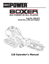
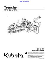
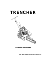
Toro High-Torque Trencher Head, Compact Tool Carrier User manual

Type
User manual

This manual is also suitable for

FormNo.3420-725RevA
High-TorqueTrencherHeadand
High-SpeedTrencherHead
CompactToolCarrier
ModelNo.22473—SerialNo.402000000andUp
ModelNo.22474—SerialNo.402000000andUp
Registeratwww.Toro.com.
OriginalInstructions(EN)
*3420-725*A
ThisproductcomplieswithallrelevantEuropean
directives;fordetails,pleaseseetheseparateproduct
specicDeclarationofConformity(DOC)sheet.
WARNING
CALIFORNIA
Proposition65Warning
Thisproductcontainsachemical
orchemicalsknowntotheStateof
Californiatocausecancer,birthdefects,
orreproductiveharm.
Useofthisproductmaycauseexposure
tochemicalsknowntotheStateof
Californiatocausecancer,birthdefects,
orotherreproductiveharm.
Introduction
Thetrencherheadsareattachmentsdesignedforuse
oncompacttoolcarrierswithavarietyofboomsand
chainstodigtrenchesinsoiltofacilitatetheburyingof
cablingandpiping.Theyarenotintendedforusein
cuttinghardmaterialssuchaswoodorconcrete.
Readthisinformationcarefullytolearnhowtooperate
andmaintainyourproductproperlyandtoavoid
injuryandproductdamage.Youareresponsiblefor
operatingtheproductproperlyandsafely.
YoumaycontactT orodirectlyatwww.T oro.com
forproductsafetyandoperationtrainingmaterials,
accessoryinformation,helpndingadealer,orto
registeryourproduct.
Wheneveryouneedservice,genuineToroparts,or
additionalinformation,contactanAuthorizedService
DealerorT oroCustomerServiceandhavethemodel
andserialnumbersofyourproductready.Figure1
identiesthelocationofthemodelandserialnumbers
ontheproduct.Writethenumbersinthespace
provided.
Important:Withyourmobiledevice,youcan
scantheQRcodeontheserialnumberdecal(if
equipped)toaccesswarranty,parts,andother
productinformation.
g244478
Figure1
1.Modelandserialnumberlocation
ModelNo.
SerialNo.
Thismanualidentiespotentialhazardsandhas
safetymessagesidentiedbythesafety-alertsymbol
(Figure2),whichsignalsahazardthatmaycause
seriousinjuryordeathifyoudonotfollowthe
recommendedprecautions.
g000502
Figure2
1.Safety-alertsymbol
Thismanualuses2wordstohighlightinformation.
Importantcallsattentiontospecialmechanical
informationandNoteemphasizesgeneralinformation
worthyofspecialattention.
©2018—TheToro®Company
8111LyndaleAvenueSouth
Bloomington,MN55420
2
Contactusatwww.Toro.com.
PrintedintheUSA
AllRightsReserved
Contents
Safety.......................................................................3
GeneralSafety...................................................3
SlopeSafety.......................................................4
TrencherSafety..................................................4
MaintenanceandStorageSafety........................4
SafetyandInstructionalDecals..........................4
Setup........................................................................6
1InstallingtheBoomandDigging
Chain..............................................................6
2InstallingtheSafetyBar...................................7
3InstallingtheSpoilsAuger................................7
4CheckingtheBearingCaseLube
Level...............................................................8
ProductOverview.....................................................9
Specications....................................................9
Attachments/Accessories...................................9
Operation..................................................................9
InstallingandRemovingtheAttachment.............9
DiggingaTrench..............................................10
OffsettingtheTrencher.....................................10
TransportPosition.............................................11
TransportingtheTrencheronaTrailer...............11
OperatingTips..................................................12
Maintenance...........................................................13
RecommendedMaintenanceSchedule(s)...........13
GreasingtheTrencher......................................13
ServicingtheBearingCaseLube......................14
AdjustingtheDiggingChainTension.................14
FlippingaWornBoom......................................15
ReplacingtheDiggingTeeth.............................15
ReplacingtheDriveSprocket...........................15
Storage...................................................................16
Safety
DANGER
Theremaybeburiedutilitylinesinthework
area.Diggingintothemmaycauseashock
oranexplosion.
Havethepropertyorworkareamarkedfor
buriedlinesanddonotdiginmarkedareas.
Contactyourlocalmarkingserviceorutility
companytohavethepropertymarked(for
example,intheUS,call811orinAustralia,
call1100forthenationwidemarkingservice).
GeneralSafety
Alwaysfollowallsafetyinstructionstoavoidserious
injuryordeath.
Alwayscarrytheattachmentclosetotheground;
refertoTransportPosition(page11).
Havethepropertyorworkareamarkedforburied
linesandotherobjects,anddonotdiginmarked
areas.
ReadandunderstandthecontentofthisOperators
Manualbeforestartingtheengine.
Useyourfullattentionwhileoperatingthe
machine.Donotengageinanyactivitythat
causesdistractions;otherwise,injuryorproperty
damagemayoccur.
Neverallowchildrenoruntrainedpeopleto
operatethemachine.
Keepyourhandsandfeetawayfromthemoving
componentsandattachments.
Donotoperatethemachinewithouttheguards
andothersafetyprotectivedevicesinplaceand
workingonthemachine.
Keepbystandersandpetsasafedistanceaway
fromthemachine.
Stopthemachine,shutofftheengine,andremove
thekeybeforeservicing,fueling,orunclogging
themachine.
Improperlyusingormaintainingthismachinecan
resultininjury.Toreducethepotentialforinjury,
complywiththesesafetyinstructionsandalwayspay
attentiontothesafety-alertsymbol,whichmeans
Caution,Warning,orDanger—personalsafety
instruction.Failuretocomplywiththeseinstructions
mayresultinpersonalinjuryordeath.
Youcanndadditionalsafetyinformationwhere
neededthroughoutthisOperatorsManual.
3
SlopeSafety
Operatethemachineupanddownslopeswith
theheavyendofthemachineuphill.Weight
distributionchangeswithattachments.This
attachmentmakesthefrontofmachinetheheavy
end.
Keeptheattachmentintheloweredposition
whenonslopes.Raisingtheattachmentona
slopeaffectsthestabilityofthemachine.
Slopesareamajorfactorrelatedtolossofcontrol
andtip-overaccidents,whichcanresultinsevere
injuryordeath.Operatingthemachineonany
slopeoruneventerrainrequiresextracaution.
Establishyourownproceduresandrulesfor
operatingonslopes.Theseproceduresmust
includesurveyingthesitetodeterminewhich
slopesaresafeformachineoperation.Always
usecommonsenseandgoodjudgmentwhen
performingthissurvey.
Slowdownanduseextracareonhillsides.Ground
conditionscanaffectthestabilityofthemachine.
Avoidstartingorstoppingonaslope.Ifthe
machinelosestraction,proceedslowly,straight
downtheslope.
Avoidturningonslopes.Ifyoumustturn,turn
slowlyandkeeptheheavyendofthemachine
uphill.
Keepallmovementsonslopesslowandgradual.
Donotmakesuddenchangesinspeedor
direction.
Ifyoufeeluneasyoperatingthemachineona
slope,donotdoit.
Watchforholes,ruts,orbumps,asuneventerrain
couldoverturnthemachine.Tallgrasscanhide
obstacles.
Usecautionwhenoperatingonwetsurfaces.
Reducedtractioncouldcausesliding.
Donotoperatethemachineneardrop-offs,
ditches,embankments,orbodiesofwater.The
machinecouldsuddenlyrolloverifawheelor
trackgoesovertheedgeortheedgecavesin.
Maintainasafedistancebetweenthemachine
andanyhazard.
Donotremoveoraddattachmentsonaslope.
Donotparkthemachineonahillsideorslope.
TrencherSafety
Keepyourhands,feet,andanyotherpartofyour
bodyorclothingawayfrommovingteeth,auger,
orotherparts.
Forwheeledtractionunits,usethecounterweight
onthetractionunitwhenusingtheattachment.
Useasafety-barextensiononaboomover61cm
(2ft).
Lookbehindanddownbeforebackingupto
ensurethatthepathisclear.
MaintenanceandStorage
Safety
Checkfastenersatfrequentintervalsforproper
tightnesstoensurethattheequipmentisinsafe
operatingcondition.
RefertotheOperator’sManualforimportant
detailsifyoustoretheattachmentforanextended
periodoftime
Maintainorreplacesafetyandinstructionlabels,
asnecessary.
SafetyandInstructionalDecals
Safetydecalsandinstructionsareeasilyvisibletotheoperatorandarelocatednearanyarea
ofpotentialdanger.Replaceanydecalthatisdamagedormissing.
decal99-9952
99-9952
1.Cuttinghazard,chainandauger—stayawayfrommovingpartsandkeepbystandersawayfromthemachine.
2.Warning—shutofftheengineandremovethekeybeforeperformingandmaintenanceorrepairs.
3.Explosionand/orelectricshockhazard—donotdiginareaswithburiedgasorpowerlines.
4
decal99-9953
99-9953
1.Explosionand/orelectricshockhazard—donotdiginareaswithburiedgasorpowerlines.
decal115-1497
115-1497
1.Crushinghazardofhand;crushinghazardoffoot—keepbystandersawayfromthemachine;keepawayfrommovingparts.
5
Setup
LooseParts
Usethechartbelowtoverifythatallpartshavebeenshipped.
ProcedureDescription
Qty.
Use
Boomassembly(soldseparately)
1
1
Chainassembly(soldseparately)
1
Installtheboomanddiggingchain.
Safetybar
1
Safetybarextension(withboomsover
61cm(2ft)only)
1
Bolts(withboomsover61cm(2ft)only)
2
2
Locknuts(withboomsover61cm(2ft)
only)
2
Installthesafetybar.
3
Nopartsrequired
Installthespoilsauger.
4
Nopartsrequired
Checkthebearingcaselubelevel.
1
InstallingtheBoomand
DiggingChain
Partsneededforthisprocedure:
1
Boomassembly(soldseparately)
1
Chainassembly(soldseparately)
Procedure
1.Raisethetrencherabout15cm(6inches)off
theground.
2.Shutofftheengineandremovethekey.
3.Removetheboltandnutsecuringthespoils
augerandremovetheauger(Figure3).
Note:Retaintheboltsandnutsforinstallation
later.
g244576
Figure3
1.Locknut(1/2inch)
6.Adjustingbolt
2.Spoilsauger
7.Jamnut
3.Bolt(1/2x3-3/4inches)8.Nut(5/8inch)
4.Bolt(5/8x3-1/2inches)
9.Doublewasher
5.Boom10.Drivesprocket
4.Removethe2bolts(5/8x3-1/2inches),2nuts
(5/8inch),and2doublewashersfromthesides
oftheboom(Figure3).
5.Loosentheadjustingboltandjamnut(Figure3).
6.Slidetheboomoverthearmonthedrivehead.
7.Installthebolts,nuts,anddoublewashers
removedpreviouslyfromtheboom,butdonot
tightenthem.
6
8.Ifthechainisnotconnected,connectthelinks
bypressingorhammeringtheclevispinsupplied
withthechainthroughthelinks.
Important:T oavoidbendingthechainlinks,
placeblocksunderandbetweenthelinkswhen
hammeringtheclevispin.
9.Securetheclevispinwiththecotterpinsupplied
withthechain.
10.Loopthediggingchainovertheaugerdriveshaft
andontothedrivesprocket,ensuringthatthe
diggingteethpointforwardontheupperspan.
11.Settheupperspanofthechainintoplaceon
thetrencherboom,thenwrapthechainaround
therollerattheendoftheboom.
12.Threadtheadjustmentboltintotheboomand
turnitinuntilthereis3.8to6.3cm(1-1/2to2-1/2
inches)ofslackinthechainonthebottomspan.
13.Threadthejamnutdowntheadjustingboltand
tightenitsecurelyagainsttheboom.
14.Torquethe2boltsandnutssecuringtheboom
to183to223N∙m(135to165ft-lb).
2
InstallingtheSafetyBar
Partsneededforthisprocedure:
1
Safetybar
1
Safetybarextension(withboomsover61cm(2ft)
only)
2
Bolts(withboomsover61cm(2ft)only)
2
Locknuts(withboomsover61cm(2ft)only)
Procedure
1.Removethebolts,washers,andangenuts
fromtheupperleftcornerofthetrencherframe
(Figure4).
g244621
Figure4
1.Bolt(5/8x3inches)4.Nut(5/8inch)
2.Bolt(5/8x4inches)5.Safetybar
3.Washer
2.Usingthefastenersremovedpreviously,install
thetrenchersafetybarasillustratedin(Figure
4).
3.Torquetheboltsandnutsto257to311N∙m
(190to230ft-lb).
4.Ifyouhaveaboomover61cm(2ft),securethe
safety-barextension(suppliedwiththeboom)
overtheendofthesafetybarandsecureit
usingthe2boltsandlocknutssuppliedwiththe
extension(Figure5).
g244620
Figure5
Safety-barextensionfor91cm(3ft)shown.
1.Bolt(1/2x3inch)3.Safety-barextension
2.Nut(1/2inch)
7
3
InstallingtheSpoilsAuger
NoPartsRequired
Procedure
Beforeoperatingthetrencher,installandpositionthe
spoilsaugertoworkcorrectlywiththediggingchain
congurationyouareusing.Ifyoudonotpositionthe
spoilsaugercorrectly,youcoulddamagethetrencher.
1.Usetheboltandnutremovedfromtheauger
previouslytosecureitinthecorrectholes,as
describedinthefollowinglist:
Note:Referto(Figure6)whenperformingthis
procedure.
10cm(4inch)chainconguration
Usingtheholeclosesttotheaugerbladein
theendoftheaugerwith2holes,connect
theaugertotheinnerholeontheshaft.
15cm(6inch)chainconguration
Usingtheholefarthestfromtheaugerblade
intheendoftheaugerwith2holes,connect
theaugertotheinnerholeontheshaft.
20cm(8inch)chainconguration
Usingtheendoftheaugerwith1hole,
connecttheaugertotheinnerholeonthe
shaft.
25or30cm(12inch)chainconguration
Usingtheendoftheaugerwith1hole,
connecttheaugertotheouterholeonthe
shaft.
g244663
Figure6
1.Auger
4.Connecttheseholesfora
20cm(8inch)chain.
2.Connecttheseholesfora
10cm(4inch)chain.
5.Connecttheseholesfora
30cm(12inch)chain.
3.Connecttheseholesfora
15cm(6inch)chain.
2.Torquetheboltandnutto101N∙m(75ft-lb).
4
CheckingtheBearingCase
LubeLevel
NoPartsRequired
Procedure
Beforeoperatingthetrencher,checktoensurethat
thebearingcaseislledwithgearlube;referto
CheckingtheBearingCaseLubeLevel(page14).
8
ProductOverview
Specications
Note:Specicationsanddesignaresubjectto
changewithoutnotice.
Width,with91cm(3ft)boom89cm(35inches)
Length,with91cm(3ft)boom165cm(65inches)
Height,with91cm(3ft)boom61cm(24inches)
Weight,with91cm(3ft)boom177kg(390lb)
Maximumtrenchdepth,with
61cm(2ft)boom
61cm(24inches)ata65
degreeboomangle
Maximumtrenchdepth,with
91cm(3ft)boom
91cm(36inches)ata65
degreeboomangle
Maximumtrenchdepth,with
122cm(4ft)boom
122cm(48inches)ata65
degreeboomangle
Attachments/Accessories
AselectionofToroapprovedattachmentsand
accessoriesisavailableforusewiththemachine
toenhanceandexpanditscapabilities.Contact
yourAuthorizedServiceDealerorauthorizedToro
distributororgotowww.T oro.comforalistofall
approvedattachmentsandaccessories.
Toensureoptimumperformanceandcontinuedsafety
certicationofthemachine,useonlygenuineT oro
replacementpartsandaccessories.Replacement
partsandaccessoriesmadebyothermanufacturers
couldbedangerous,andsuchusecouldvoidthe
productwarranty.
Operation
InstallingandRemoving
theAttachment
RefertotheOperator’sManualforthetractionunitfor
theinstallationandremovalprocedure.
Important:Beforeinstallingtheattachment,
positionthemachineonalevelsurface,ensure
thatthemountplatesarefreeofanydirtordebris,
andensurethatthepinsrotatefreely.Ifthepins
donotrotatefreely,greasethem.
Note:Alwaysusethetractionunittoliftandmove
theattachment.
WARNING
Ifyoudonotfullyseatthequick-attach
pinsthroughtheattachmentmountplate,
theattachmentcouldfalloffthemachine,
crushingyouorbystanders.
Ensurethatthequick-attachpinsarefully
seatedintheattachmentmountplate.
WARNING
Hydraulicuidescapingunderpressurecan
penetrateskinandcauseinjury.Fluidinjected
intotheskinmustbesurgicallyremoved
withinafewhoursbyadoctorfamiliarwith
thisformofinjury;otherwise,gangrenemay
result.
Ensurethatallhydraulic-uidhoses
andlinesareingoodconditionandall
hydraulicconnectionsandttingsaretight
beforeapplyingpressuretothehydraulic
system.
Keepyourbodyandhandsawayfrom
pinholeleaksornozzlesthateject
high-pressurehydraulicuid.
Usecardboardorpapertondhydraulic
leaks;neveruseyourhands.
9
CAUTION
Hydrauliccouplers,hydrauliclines/valves,
andhydraulicuidmaybehot.Ifyoucontact
hotcomponents,youmaybeburned.
Weargloveswhenoperatingthehydraulic
couplers.
Allowthemachinetocoolbeforetouching
hydrauliccomponents.
Donottouchhydraulicuidspills.
DiggingaTrench
1.Ifyourtractionunithasaspeedselector,setitto
theSLOW(turtle)position,thenstarttheengine.
2.Pulltheauxiliaryhydraulicslevertotheoperator
griptoengagethetrencher.
3.Slowlylowerthetrenchertothegroundsothat
theboomandchainareparalleltotheground.
4.Begininsertingthenoseoftheboomandchain
intothegroundbyslowlyraisingthetrenchera
fewcentimeters(inches)offthegroundwhile
tiltingthenosedownintothegroundgradually.
5.Oncethetrencherboomisinthegroundata45
to60degreeangle,slowlylowerthetrencher
untilthespoilsaugerisjustabovetheground.
6.Ensurethatallpartsofthetrencherare
functioningcorrectly.
7.Slowlymovethetractionunitrearwardtoextend
thetrench.
Note:Ifyoumovetoofast,thetrencherwillstall.
Ifitstalls,raiseitslightly,slowlydriveforward,or
reversethechaindirectionmomentarily.
8.Whennished,raisethetrencherandboomout
ofthetrenchbytiltingtheattachmentrearward,
thenstopthetrencherbymovingtheauxiliary
hydraulicsleverintoneutral.
OffsettingtheTrencher
Youcanmovethetrenchertotherightsideofthe
trencherframetoallowyoutotrenchclosetobuildings
andotherobstacles.
1.Lowerthetrenchertotheground,engagethe
parkingbrake(ifequipped),shutofftheengine,
andremovethekey.
2.Disconnectthehydrauliclinesfromthetrencher.
WARNING
Hydraulicuidescapingunderpressure
canpenetrateskinandcauseinjury.
Fluidinjectedintotheskinmustbe
surgicallyremovedwithinafewhoursby
adoctorfamiliarwiththisformofinjury;
otherwise,gangrenemayresult.
Keepyourbodyandhandsawayfrom
pinholeleaksornozzlesthateject
high-pressurehydraulicuid.
Usecardboardorpapertond
hydraulicleaks;neveruseyour
hands.
3.Removethe6boltssecuringthetrencherhead
totheframe(Figure7).
g244771
Figure7
Safetybarnotshown
1.Bolt(6)2.Lefthoseguide
4.Movetheframetotheleft,aligningtheholesin
therightsideoftheframewiththoseinthehead.
5.Attachtheheadtotheframewiththe6bolts
removedpreviously(Figure8).
10
g244770
Figure8
Safetybarnotshown
1.Bolt(6)
6.Torquetheboltsto257to311N∙m(190to230
ft-lb).
7.Removethebolt(5/8x3inches),2bolts(5/8x4
inches),3washers,and3nutsfromthesafety
barandremovethebar.
8.Removethe2bolts(5/8x3inches),2washers,
and2nutssecuringtherightsideoftheupper
frameandmovethemtothecorresponding
holesontheleft(Figure9).
g244769
Figure9
1.Bolt—5/8x4inches(2)4.Safetybar
2.Washer(5)5.Bolt—5/8x3inches(3)
3.Nut(5)
9.Installthesafetybaroverthetrencherchain
usingthe3bolts,washers,andangenuts
removedpreviously(Figure9).
10.Torqueall5boltsandnutsto257to311N∙m
(190to230ft-lb).
11.Movethehosesfromthehoseguideontopof
thetrenchertothehoseguideontheleftside
(Figure7).
TransportPosition
Whentransportingtheattachment,keepitasclose
tothegroundaspossible,nomorethan15cm(6
inches)abovethelowestposition.Tiltitrearward.
g245257
Figure10
1.Nomorethan15cm(6
inches)abovethelowest
position
2.Tilttheattachment
rearward.
TransportingtheTrencher
onaTrailer
Placethetrencheronatrailerortruckcapableof
carryingit.Securelytiethetrenchertothetraileror
truckusingtiestrapsappropriatefortheweightofthe
trencherandforhighwayuse.
11
OperatingTips
Cleantheareaoftrash,branches,androcks
beforetrenchingtopreventequipmentdamage.
Alwaysbegintrenchingwiththeslowestground
speedpossible.Increasespeedifconditions
permit.
Alwaysusefullthrottle(maximumenginespeed)
whentrenching.
Alwaystrenchbackward(i.e.,inreverse).
Nevertransportthetrencherwiththeloaderarms
raised.Keepthearmsloweredandthetrencher
tiltedup.
Whentrenching,thespoilsaugershouldjustclear
theoriginalgroundsurfacetoobtainmaximumsoil
removal.
Trenchata45to60degreeangleforbestresults.
Todigatrenchfaster,controlthedepthwith
periodicadjustmentsoftheloaderarms.
Ifyourtractionunithasaspeedselector,setitto
theSLOW(turtle)position.
Ifyourtractionunithasaowdivider(present
onsomewheeledtractionunits),adjustitto
approximatelythe10o’clockposition.
Ifthetrencherbindsinthesoil,pushtheauxiliary
hydraulicsleverfullyforwardtoreversethechain
direction.Oncethechainisloose,pullthelever
rearwardagainandcontinuetrenching.
Ifyouneedthenishedtrenchtobecleaner
thanwhatispossiblewiththetrencher,you
canpurchaseacrumberfromyourdealer.The
crumbermountsontothetrencherandscrapesthe
trenchcleanasyourunthetrencher.
Toimprovethequalityoftrencheslessthan61cm
(24inches)deep,usea61cm(24inch)boomon
thetrencher.
12
Maintenance
RecommendedMaintenanceSchedule(s)
MaintenanceService
Interval
MaintenanceProcedure
Beforeeachuseordaily
Greasethetrencher.
Inspecttheboomforwear.
Every25hours
Checkthegear-lubelevel.
Adjustthediggingchaintension.
Inspecttheboomforwear.
Every200hours
Changethegearlube.
Beforestorage
Greasethetrencher.
Checkthegear-lubelevel.
CAUTION
Ifyouleavethekeyintheswitch,someonecouldaccidentlystarttheengineandseriously
injureyouorotherbystanders.
Removethekeyfromtheswitchbeforeyouperformanymaintenance.
GreasingtheTrencher
ServiceInterval:Beforeeachuseordaily
Beforestorage
Grease2ttings,asshowninFigure11andFigure
12,everydayandimmediatelyaftereverywashing.
GreaseType:General-purposegrease
1.Parkthemachineonalevelsurface,disengage
theauxiliaryhydraulicslever,lowerthe
attachment,andengagetheparkingbrake(if
equipped).
2.Shutofftheengineandremovethekey
3.Cleanthegreasettingswitharag.
4.Connectagreaseguntoeachtting.
5.Pumpgreaseintothettingsuntilgreasebegins
tooozeoutofthebearings.
6.Wipeupanyexcessgrease.
g244994
Figure11
g244995
Figure12
13
ServicingtheBearingCase
Lube
ServiceInterval:Every25hours—Checkthe
gear-lubelevel.
Every200hours—Changethegearlube.
Beforestorage—Checkthegear-lubelevel.
CheckingtheBearingCaseLube
Level
Gearlubetype:SAE90-140APIserviceGL-4orGL-5
Capacity:0.5L(17oz)
1.Parkthemachineonalevelsurface,disengage
theauxiliaryhydraulicslever,lowerthe
attachment,andengagetheparkingbrake(if
equipped).
2.Tiltthetrenchersothattheboomisparallelwith
theground.
3.Shutofftheengineandremovethekey
4.Cleantheareaaroundthell-holeplugonthe
bearingcase(Figure13).
g244664
Figure13
1.Fill-holeplugonthebearingcase
5.Removetheplugfromthellhole(Figure13).
6.Lookintheholeandcheckthelevelofgearlube
inthebearingcase.
Note:Thelevelshouldbeuptothebottomof
thehole;ifitisnot,addgearlube.
7.Replacetheplugandtorqueitto20to23N∙m
(15to17ft-lb).
ChangingtheGearLube
1.Parkthemachineonalevelsurface,disengage
theauxiliaryhydraulicslever,lowerthe
attachment,andengagetheparkingbrake(if
equipped).
2.Shutofftheengineandremovethekey
3.Cleantheareaaroundthell-holeplugonthe
bearingcase(Figure13).
4.Removetheplugfromthellhole(Figure13).
5.Liftthetrencheruntiltheboomisvertical,
drainingthelubethroughthellholeandintoa
pan.
6.Returnthetrenchertotheground.
7.Fillthebearingcasewithgearlubeuntilitcomes
outofthellhole.
8.Replacetheplugandtorqueitto20to23N∙m
(15to17ft-lb).
AdjustingtheDigging
ChainTension
ServiceInterval:Every25hours—Adjustthedigging
chaintension.
Withthetrencherparalleltotheground,ensurethat
thereis3.8to6.3cm(1-1/2to2-1/2inches)between
thebottomoftheboomandthetopofthebottom
chainspan.Ifnot,adjustthechainusingthefollowing
procedure:
Important:Donotovertightenthechain.Excess
chaintensionmaydamagedrivecomponents.
1.Parkthemachineonalevelsurface,disengage
theauxiliaryhydraulicslever,lowerthe
attachment,andtiltitsothattheboomisparallel
withtheground.Engagetheparkingbrake(if
equipped).
2.Shutofftheengineandremovethekey
3.Loosenthe2boltsandnutssecuringtheboom
tothetrencherarm(Figure3).
4.Loosenthejamnutsecuringtheadjustmentbolt
(Figure3).
5.Turntheadjustmentboltinoroutasneededto
achievethedesiredtension.
6.Tightenthejamnut.
7.Torquethe2boltsandnutssecuringtheboom
to183to223N∙m(135to165ft-lb).
14
FlippingaWornBoom
ServiceInterval:Every25hours—Inspecttheboom
forwear.
Inspectthebottomoftheboomforwear,ifitisworn,
completethefollowing:
Note:Ifyouhavealreadyippedtheboomonce,
replacetheboomwhenbothsidesareworn.
1.Parkthemachineonalevelsurface,disengage
theauxiliaryhydraulicslever,lowerthe
attachment,andengagetheparkingbrake(if
equipped).
2.Shutofftheengineandremovethekey
3.Removethe2boltsandnutssecuringtheboom
tothetrencherarm(Figure3).
4.Loosenthejamnutontheadjustingboltinthe
boom(Figure3).
5.Loosentheadjustingboltuntilyoucanremove
thechainfromtheboom(Figure3).
6.Removethechainfromthedrivesprocketand
boom.
7.Removetheboom,ipitoversothebottom
becomesthetop(orifyouhavealreadyipped
itonce,replaceit),andinstalltheboomagain.
8.Replacethenuts,bolts,andwasherssecuring
theboom.
9.Installthechainoverthedrivesprocketand
frontroller.
10.Adjustthechaintension;refertoAdjustingthe
DiggingChainT ension(page14).
ReplacingtheDigging
Teeth
ServiceInterval:Beforeeachuseordaily—Inspect
theboomforwear.
Duetothehighamountofwearplacedonthedigging
teeth,youneedtoreplacethemperiodically.
Toreplaceasingletooth,removetheboltsandnuts
securingthetoothtoremoveit,theninstallanew
toothinthesameposition.Torquetheboltssecuring
theteethto37to45N∙m(27to33ft-lb).
g245068
Figure14
1.Nut3.Nut
2.Tooth
ReplacingtheDrive
Sprocket
Overtime,thedrivesprocketwillwear,especially
whenusedinsandyorclaysoils.Whenthishappens,
thediggingchainwillbegintoslip.Ifthechainslips,
replacethedrivesprocketasfollows:
1.Parkthemachineonalevelsurface,disengage
theauxiliaryhydraulicslever,lowerthe
attachment,andengagetheparkingbrake(if
equipped).
2.Raisethetrencherafewcentimeters(inches)
abovetheground.
3.Shutofftheengineandremovethekey
4.Removethespoilsauger(Figure15).
g244973
Figure15
1.Spoilsauger
3.Bolts
2.Drivesprocket
15
5.Loosenthe2boltsandnutssecuringtheboom
tothetrencherarm(Figure3).
6.Loosenthejamnutontheadjustingboltinthe
boom(Figure3).
7.Loosentheadjustingboltuntilyoucanremove
thechainfromtheboom(Figure3).
8.Removethechainfromthedrivesprocket.
9.Removethe6boltssecuringthedrivesprocket
(Figure15).
10.Removeanddiscardthedrivesprocket(Figure
15).
11.Cleanthesprocketmountingsurfaceonthe
trencher.
12.Slidethenewsprocketontotheshaftas
illustratedin(Figure15).
Important:Thearrowonthesprocketface
shouldbevisiblefromtherightsideofthe
trencherandshouldpointinaclockwise
direction;ifnot,turnthesprocketaround.
13.Threadthe6boltsintothesprocketngertight
(Figure15).
14.Slowlybegintighteningtheboltsprogressing
aroundthesprocketuntilallboltsaretorquedto
129to155N∙m(95to115ft-lb).
Important:Tighteneachboltonlyhalfway
rst,workingyourwayaroundthe6bolts,
thenreturntoeachboltinturnandtorque
themtothespecicationsgiveninstep13.
15.Loopthechainovertheaugerdriveshaftand
ontothedrivesprocket,ensuringthattheteeth
pointforwardontheupperspan.
16.Settheupperspanofthechainintoplaceon
thetrencherboom,thenwrapthechainaround
therollerattheendoftheboom.
17.Threadtheadjustmentboltintotheboomand
turnitinuntilthereis3.8to6.3cm(1-1/2to2-1/2
inches)ofslackinthechainonthebottomspan.
18.Threadthejamnutdowntheadjustingboltand
tightenitsecurelyagainsttheboom.
19.Torquethe2boltsandnutssecuringtheboom
to183to223N∙m(135to165ft-lb).
20.Installthespoilsauger;referto3Installingthe
SpoilsAuger(page7).
Storage
1.Beforelongtermstorage,brushthedirtfromthe
attachment.
2.Checktheconditionofthediggingchain.Adjust
thediggingchaintension;refertoAdjustingthe
DiggingChainTension(page14).Replaceany
wornordamagedteeth;refertoReplacingthe
DiggingT eeth(page15).
3.Greasethetrencher;refertoGreasingthe
Trencher(page13)
4.Checkbearingcaselubelevel;refertoChecking
theBearingCaseLubeLevel(page14).
5.Checkandtightenallbolts,nuts,andscrews.
Repairorreplaceanypartthatisdamagedor
worn.
6.Ensurethatallhydrauliccouplersareconnected
togethertopreventcontaminationofthe
hydraulicsystem.
7.Paintallscratchedorbaremetalsurfaces.Paint
isavailablefromyourAuthorizedServiceDealer.
8.Storethetrencherinaclean,drygarageor
storagearea.Coverthetrenchertoprotectit
andkeepitclean.
16
Notes:
Notes:
DeclarationofIncorporation
TheToroCompany,8111LyndaleAvenueSouth,Bloomington,MN,USAdeclaresthatthefollowingunit(s)
conform(s)tothedirectiveslisted,wheninstalledinaccordancewiththeaccompanyinginstructionsontocertain
ToromodelsasindicatedontherelevantDeclarationsofConformity.
ModelNo.
SerialNo.
ProductDescriptionInvoiceDescription
GeneralDescription
Directive
22473315000001andUpHigh-TorqueTrencherHead
HIGHTORQUETRENCHER
HEAD
Trencher
2006/42/EC
22474315000001andUp
High-SpeedTrencherHead
HIGHTORQUETRENCHER
HEAD
Trencher
2006/42/EC
RelevanttechnicaldocumentationhasbeencompiledasrequiredperPartBofAnnexVIIof2006/42/EC.
Wewillundertaketotransmit,inresponsetorequestsbynationalauthorities,relevantinformationonthispartly
completedmachinery.Themethodoftransmissionshallbeelectronictransmittal.
ThismachineryshallnotbeputintoserviceuntilincorporatedintoapprovedToromodelsasindicatedonthe
associatedDeclarationofConformityandinaccordancewithallinstructions,wherebyitcanbedeclaredin
conformitywithallrelevantDirectives.
Certied:
AuthorizedRepresentative:
MarcelDutrieux
ManagerEuropeanProductIntegrity
ToroEuropeNV
Nijverheidsstraat5
2260Oevel
Belgium
JoeHager
Sr.EngineeringManager
Tel.+3216386659
8111LyndaleAve.South
Bloomington,MN55420,USA
February7,2018
EuropeanPrivacyNotice
TheInformationT oroCollects
ToroWarrantyCompany(T oro)respectsyourprivacy.Inordertoprocessyourwarrantyclaimandcontactyouintheeventofaproductrecall,weaskyou
tosharecertainpersonalinformationwithus,eitherdirectlyorthroughyourlocalT orocompanyordealer.
TheT orowarrantysystemishostedonserverslocatedwithintheUnitedStateswhereprivacylawmaynotprovidethesameprotectionasapplies
inyourcountry.
BYSHARINGYOURPERSONALINFORMATIONWITHUS,YOUARECONSENTINGTOTHEPROCESSINGOFYOURPERSONALINFORMATION
ASDESCRIBEDINTHISPRIVACYNOTICE.
TheWayT oroUsesInformation
Toromayuseyourpersonalinformationtoprocesswarrantyclaims,tocontactyouintheeventofaproductrecallandforanyotherpurposewhichwetell
youabout.T oromayshareyourinformationwithToro'safliates,dealersorotherbusinesspartnersinconnectionwithanyoftheseactivities.Wewillnot
sellyourpersonalinformationtoanyothercompany.Wereservetherighttodisclosepersonalinformationinordertocomplywithapplicablelawsand
withrequestsbytheappropriateauthorities,tooperateoursystemsproperlyorforourownprotectionorthatofotherusers.
RetentionofyourPersonalInformation
Wewillkeepyourpersonalinformationaslongasweneeditforthepurposesforwhichitwasoriginallycollectedorforotherlegitimatepurposes
(suchasregulatorycompliance),orasrequiredbyapplicablelaw.
Toro'sCommitmenttoSecurityofYourPersonalInformation
Wetakereasonableprecautionsinordertoprotectthesecurityofyourpersonalinformation.Wealsotakestepstomaintaintheaccuracyandcurrent
statusofpersonalinformation.
AccessandCorrectionofyourPersonalInformation
Ifyouwouldliketorevieworcorrectyourpersonalinformation,pleasecontactusbyemailat[email protected].
AustralianConsumerLaw
AustraliancustomerswillnddetailsrelatingtotheAustralianConsumerLaweitherinsidetheboxoratyourlocalT oroDealer.
374-0282RevC
  • Page 1 1
  • Page 2 2
  • Page 3 3
  • Page 4 4
  • Page 5 5
  • Page 6 6
  • Page 7 7
  • Page 8 8
  • Page 9 9
  • Page 10 10
  • Page 11 11
  • Page 12 12
  • Page 13 13
  • Page 14 14
  • Page 15 15
  • Page 16 16
  • Page 17 17
  • Page 18 18
  • Page 19 19
  • Page 20 20

Toro High-Torque Trencher Head, Compact Tool Carrier User manual

Type
User manual
This manual is also suitable for

Ask a question and I''ll find the answer in the document

Finding information in a document is now easier with AI