Page is loading ...

1
NOTE: DIAGRAMS & ILLUSTRATIONS ARE NOT TO SCALE.
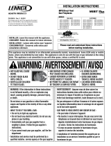
Figure 1
HEARTH PRODUCTS
KITS AND ACCESSORIES
INSTALLATION INSTRUCTIONS FOR SV4.5HTSS, SV4.5-20SSWSK AND ALL DERIVATIONS
OF THE SF-HTSS; SFKIT12-SS, SFKIT18-SS, SFKIT24SS, SFKIT26SS AND SFKIT48-SS KITS
SMALL SQUARE
HORIZONTAL TERMINATION
P/N 750204M
REV. H 04/2018
GENERAL INFORMATION
Information provided here is supplemental to instructions provided with
each fireplace and may, for the most part, be redundant to that information.
The intent of this document is to provide complete instructions pertaining
to the installation of the before-mentioned terminations, particularly any
instructions that are exclusive to the installations of these terminations.
The SV4.5HTSS, SV4.5-20SSWSK and all derivations of the SF-HTSS;
SFKIT12-SS, SFKIT18-SS, SFKIT24-SS, SFKIT36-SS, and SFKIT48-SS
are intended for use ONLY with Innovative Hearth Products (IHP) 33”,
35” and select other Direct-Vent gas fireplaces listed as follows; DRC/
DRT-2033/2035, DRC/DRT-3033/3035, DRL3042, DRL6542, Aries 33/35,
AriesCD 33/35, MPD33/35, MPD3328/3530, Gemini33/35, Rhapsody42,
Sirius42, Envy35, Envy35CD, MHD35, MLDVTCD-35, SSDV-3328/3530,
SDV35N, LMDV3328, LMDV-3530, MPLDV-30 and MPLDV-35,
VeniceLightsTEN, VeniceLightsTEP, DRL4543TEN, DRL4543TEP series
gas fireplaces.
These terminations MAY NOT be used with DRC/DRT-2040/2045,
DRC/DRT-4040/4045, DRT40-ST/PF/CR/CL, DRC/DRT-3540/3545,
DRC/DRT-3040/3045, DRT35ST/PF, DRL3054, DRL6554, Aries40/45,
AriesCD40/45,Altair40/45, Envy40/45CD, Envy40CD/45CD,
Eros35ST/PF, Gemini40/45, Libra40-ST/PF/CR/CL, Scorpio-35/40/45,
ScorpioCD-35/40/45, MHD40, MPD Pro, MPD40/45, MPD4035/4540,
MPD35ST/PF, Rhapsody 54, Sirius54, Spectra, EDV, ELDV and EDVST/
PF/CR/CL series gas fireplaces.
The terminations covered by this document seamlessly integrate with all
the other components of the above mentioned fireplaces approved for
use with these terminations, and when installed in accordance with the
directions provided here and with each fireplace constitute a complete,
approved and listed installation.
*34-5/16
(872)
Back wall of chase/enclosure (including any finishing materials)
a
8-3/16 (208)
b
NOTE: Venting requirements for rear vent applications in corner installations -
the horizontal vent length “a” to “b,” must not exceed 28” (711 mm)
*17-3/16
(437)
Inches
(millimeters)
*These dimensions occur when one 45 degree
elbow is connected directly to the appliance
collar and the unit moved 1/2” (13 mm)
into the room. This 1/2” movement
is required to achieve a minimum of
5” (127 mm) in the F dimension.
*F = 5”
(127 mm)
*24-1/4
(616)
33-1/8
(841)
*48-1/2
(1232)
CORNER FRAMING WITH SQUARE HORIZONTAL
TERMINATIONS (SV4.5HTSS)
SV4.5HTSS Termination
Framing should be constructed of 2x4 or larger lumber.
7 (178)
b
SV4.5HTS
Termination
CUS
Report No. F114-140
Small Square Termination Kits
Cat. No Model Description
H5817 SV4.5-20SSWSK Small Square Termination, Horiz. 20" w/Sheild
94L10 SV4.5HTSS Small Square Termination, Horiz. - Rigid
H8915 SV4.5TK90SS Small Square Termination, Horiz. Kit w/90
Framing
Frame the fireplace in accordance with the instructions provided with the
fireplace and refer to Figures 1, 4 and 5 for any dimensions applicable
to the SV4.5HTSS, SF-HTSS terminations.

2
NOTE: DIAGRAMS & ILLUSTRATIONS ARE NOT TO SCALE.
Vertical
Rise
SV4.5E90
Elbow
Horizontal / Inclined Run SV4.5HTSS
Termination
Shown
*Ceiling
Firestop/Spacer
(SV4.5VF)
SV4.5L6/12/24/36/48
Vent Sections
Support Bracket Spacing
Every 5 ft (1.52 m)
Support
Brackets
Building
Support
Framing
Ceiling
Fireplace
Exterior
Wall
Exterior
Wall
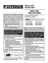
TYPICAL HORIZONTAL VENT INSTALLATION
Firestop/Spacer
SV4.5HTSS
Termination
Shown
Fireplace
*When using Secure Flex use
Firestop/Spacer (SF4.5VF)
Note: Adaptor SV4.5RCH or
SV4.5RCHA must be used to
attach the termination to the
venting system. See Steps J
and K.
Figure 2
H. Change vent direction - At transition from or
to a horizontal/inclined run, install the SV4.5E45
and SV4.5E90 elbows in the same manner as
the straight vent sections. The elbows feature
a twist section to allow them to be routed about
the center axis of their initial collar section to
align with the required direction of the next
vent run element. Twist elbow sections in a
clockwise direction only so as to avoid the
possibility of unlocking any of the previously
connected vent sections.
I. Continue installation of horizontal/inclined
sections - Continue with the installation of the
straight vent sections in horizontal/inclined run
as described in Step E. Install support straps
every 5 ft. (1.52 m) along horizontal/inclined
vent runs using conventional plumber’s tape.
See Figure 2. It is very important that the
horizontal/inclined run be maintained in a
straight (no dips) and recommended to be in
a slightly elevated plane, in a direction away
from the fireplace of 1/4" rise per foot (20 mm
per meter) which is ideal, though rise per foot
run ratios that are smaller are acceptable all the
way down to at or near level. Use a carpenter’s
level to measure from a constant surface and
adjust the support straps as necessary.
It is important to maintain the required clear-
ances to combustibles: 1" (26 mm) at all sides
for all vertical runs; and 3" (77 mm) at the
top, 1" (26 mm) at sides, and 1" (26 mm) at
the bottom for all horizontal/inclined runs.
J. Assemble vent run to exterior wall - If not
previously measured, locate the center of the
vent at the exterior wall. Prepare an opening as
described in Step B.
Square Horizontal Termination- (SV4.5 HTSS)
Assemble the venting system to a point where
the terminus of the last section is within 6"
(152mm) to 9" (228mm) inboard of the exterior
surface to which the termination is to be at-
tached, see Figure 4. Attach Adaptor SV4.5RCH
as shown in Figure 3.
NOTE: An elbow may also be attached to the
appliance collar. Attach in the same manner as
you would a vent section.
E. Attach vent components to each other -
Other vent sections may be added to the previ-
ously installed section in accordance with the
requirements of the vent tables. To add another
vent component to a length of vent run, align
the dimpled end of the component over the
inclined channel end of the previously installed
section, adjusting the radial alignment until the
four locking dimples are aligned with the inlets
of the four incline channels of the previous
section. Push the vent component against the
previous section until it fully engages, then twist
the component clockwise running the dimples
down and along the incline channels until they
seat at the end of the channels.
F. Install firestop/spacer at ceiling -
When using Secure Vent, use SV4.5VF firestop/
spacer at ceiling joists; when using Secure
Flex, use SF4.5VF firestop/spacer. If there is
living space above the ceiling level, the firestop/
spacer must be installed on the bottom side of
the ceiling. If attic space is above the ceiling,
the firestop/ spacer must be installed on the
top side of the joist. Route the vent sections
through the framed opening and secure the
firestop/spacer with 8d nails or other appropriate
fasteners at each corner.
Remember to maintain 1" (26 mm) clearance
to combustibles, framing members, and attic
or ceiling insulation when running vertical
chimney sections.
G. Support the vertical run sections -
On the vertical run, support the venting sys-
tem every 8 feet (2.4m) above the fireplace
vent outlet with field provided support straps
(Plumber's tape). Attach the straps to the vent
pipe and secure to the framing members with
nails or screws.
HORIZONTAL (OUTSIDE WALL)
TERMINATION SYSTEM
Figure 2, and Figures 7 to 13 and their associated
Horizontal Vent Tables, illustrate the various hori-
zontal venting configurations that are possible
for use with these appliances. Secure Vent pipe
applications are shown in these figures; Secure
Flex pipe may also be used. A Horizontal Vent
Table summarizes each system’s minimum and
maximum vertical and horizontal length values
that can be used to design and install the vent
components in a variety of applications. Both
of these horizontal vent systems terminate
through an outside wall. Building Codes limit
or prohibit terminating in specific areas. Refer
to the instructions provided with the fireplace.
Secure Vent SV4.5 direct vent system compo-
nents are unitized concentric pipe components
featuring positive twist lock connection.
A. Plan the vent run -
Analyze the vent routing and determine the
types and quantities of sections required
4-1/2" (114 mm), 10-1/2" (267 mm), 22-1/2"
(572 mm), 34-1/2" (877 mm) and 46-1/2"
(1181 mm) net section lengths are available.
Make allowances for elbows as indicated in
the instructions provided with the fireplace.
Maintain a minimum 1" (26 mm) clearance
to combustibles on the vertical sections.
Clearances for the horizontal runs are; 3" (77
mm) on top, 1" (26 mm) on sides, and 1" (26
mm) at the bottom.
B. Frame exterior wall opening -
Locate the center of the vent outlet on the
exterior wall. Cut and/or frame an opening,
10-1/2" x 12-1/8" (267 mm x 308mm) inside
dimensions, about this center.
C. Frame ceiling opening - If the vertical route
is to penetrate a ceiling, use plumb line to locate
the center above the appliance. Cut and/or frame
an opening, 10-1/2" x 10-1/2" (267 mm x 267
mm) inside dimensions, about this center.
D. Attach vent components to appliance - To
attach a vent component to the appliance
collar, align the dimpled end over the collar,
adjusting the radial alignment until the four
locking dimples are aligned with the inlets of
the four incline channels on the collar. Push
the vent component against the collar until
it fully engages, then twist the component
clockwise, running the dimples down and
along the incline channels until they seat at
the end of the channels. The unitized design
of the Secure Vent components will engage
and seal both the inner and outer pipe elements
with the same procedure.
Sealant and securing screws are not required.

3
NOTE: DIAGRAMS & ILLUSTRATIONS ARE NOT TO SCALE.
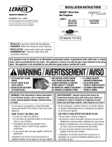
*Firestop/Spacer (SV4.5HF) shown
on the exterior side of the wall. It
may also be installed on the
interior side.
SV4.5 HTSS
Termination
Shown.
10-1/2"
(267 mm)
7"
(178)
5-1/8"
(130 mm) 12-1/8"
(308 mm)
NOTE: Centerline of Vent
Piping is NOT the Same as
the Centerline of the
Framed Opening.
6” to 48” Vent Section,
Telescopic vent section,
Elbow or Appliance Collar
Base of Appliance
3"
(77 mm)
1"
(26 mm)
Adaptor
SV4.5RCH or
SV4.5RCHA
*NOTE: When using Secure Flex
use Firestop/Spacer SF4.5HF
See Fireplace
Installation Instructions
For Min. Distance to
Base of Appliance.
* To help minimize water infiltra-
tion it is recommended that the
Firestop/Spacer (SV4.5HF) be
installed on the exterior side of
the wall.
Figure 5 - 9" to 21-1/4" Wall Thickness, SV4.5-20SSWSK Terminations
Figure 3 - Short Square Horizontal Termination (SV4.5HTSS)
Figure 4 - 6" to 9-1/4" Wall Thickness, SV4.5HTSS Terminations
If the terminus of the last section is not within
this distance, use the telescopic vent section
SV4.5LA, as the last vent section for up to 15-
3/4" (400mm). For distance greater than 15-1/4"
(400mm) use adaptor SV4.5RCHA and refer to
Table 1. This table lists venting components
needed in addition to the termination adaptor.
Also refer to the vent section length chart in
the fireplace installation instructions manual
for help on selecting additional vent sections.
Square Horizontal Termination -
(Kit No. SV4.5-20SSWSK)
Assemble the venting system to a point where
the terminus of the last section is within 6"
(152mm) to 21-1/4" (540mm) inboard of the
exterior surface to which the termination is
to be attached, see Figure 5. Attach Adaptor
SV4.5RCHA as shown in Figure 3. Go to Step
K for cutting to length instructions.
K. Attach Termination Adaptor -
Square Horizontal Termination Kit SV4.5HTSS
(with short adaptor)
Attach adaptor SV4.5RCH (provided with the
termination kit), to the vent section or telescop-
ing vent section, elbow or appliance collar as
shown in Figure 3, in the same manner as any
SV4.5 vent component (refer to Step E).
Square Horizontal Termination Kit
SV4.5-20SSWSK (with short adaptor)
Attach adaptor SV4.5RCHA (provided with the
termination kit No. SV4.5-20SSWSK), to the
vent section or telescoping vent section, elbow
or appliance collar as shown in Figure 3, in
the same manner as any SV4.5 vent component
(refer to Step E).
d) Proceed to mark the inner pipe using the
same dimension for the outer pipe, it is rec-
ommended to add 1/4" to the length to aid in
catching the mating pipe when inserting the
termination.
L. Install Firestop/Spacer at exterior wall
- When using either of the square termina-
tions, install SV4.5HF (Secure Vent), or SF4.5HF
(Secure Flex) firestop/spacer over the opening
at the exterior side of the framing, long side up,
with the 3" spacer clearance at the top as shown
in Figure 3, and nail into place. (The Firestop/
Spacer may be installed over the opening at
the interior side of the framing).
It may be necessary to cut the excess length from
the adaptor. Measure the distance from the last
venting section to the exterior surface to which
the termination is to be attached, see Figure 3.
This is the total length the adaptor must be.
a) Separate the inner and outer pipes from
the adaptor.
b) Mark the desired length of the outer pipe
measured from the dimpled end towards the
plain end.
c) Cut the excess material with sheet metal
scissors or similar tool.
Firestop/spacer (SV4.5HF)
required, but not shown
Firestop/spacer (SV4.5HF)
required, but not shown
Interior surface of finished wall
Maximum extent of vent
run relative to exterior
surface of framing
Last vent section (use telescopic
vent section [SV4.5LA], if necessary)
Adaptor
SV4.5RCH
Siding
* To prevent water infiltration in wet environments, use a silicone sealant between the
termination and the wall. High temperature sealant is not required.
*
Stucco
SV4.5HTSS Small square
termination shown
1-1/4" Maximum recess of
square termination into exterior
finishing material
SV4.5HTSS Small
square termination
shown
Cut termination collar and
adaptor for wall thickness
< 6" (153 mm)
6 to 9-1/4" (153–235 mm)
Exterior surface of framing
Exterior surface of siding
Maximum wall thickness
9-1/4" (235 mm)
Minimum wall thickness
6" (153 mm)
When using Secure Flex, use
firestop/spacer SF4.5HF
For wall thickness, refer to
Table 1
Cut termination collar and
adaptor for wall thickness
< 9" (229 mm)
Interior surface of finished wall
Maximum extent of vent
run relative to exterior
surface of framing
Last vent section (use telescopic
vent section [SV4.5LA], if necessary)
Termination
securing screw
Siding
* To prevent water infiltration in wet environments, use a silicone sealant between the
termination and the wall. High temperature sealant is not required.
*
Stucco
SV4.5HTSS Square
termination shown
1-1/4" Maximum recess
of square termination into
exterior finishing material
SV4.5HTSS Square
termination shown
9 to 21-1/4" (229–540 mm)
Exterior surface of framing
Exterior surface of siding
Maximum wall thickness
21-1/4" (540 mm)
Minimum wall thickness
9" (229 mm)
When using Secure
Flex, use firestop/spacer
SF4.5HF
Firestop/spacer (SV4.5HF)
required, but not shown

4
NOTE: DIAGRAMS & ILLUSTRATIONS ARE NOT TO SCALE.
Figure 7 -
Figure 6 -
See Table 1 as an aid in venting component selection for a particular
range of exterior wall thicknesses.
HORIZONTAL VENT FIGURES/TABLES NOTE: Secure Vent® components (rigid vent pipe and terminal) are shown
in the figures; Secure Flex® components (flexible vent pipe and terminal)
may also be used.
NOTE: SV4.5VF (Secure Vent), SF4.5VF (Secure Flex) firestop/spacer must
be used anytime vent pipe passes through a combustible floor or ceiling.
SV4.5HF (Secure Vent), SF4.5HF (Secure Flex) firestop/spacer must be used
anytime vent pipe passes through a combustible wall.
NOTE: Two 45 degree elbows may be used in place of one 90 degree elbow.
The same rise to run ratios, as shown in the venting figures for 90 elbows,
must be followed if 45 degree elbows are used.
NOTE: It is very important that the horizontal/inclined run be maintained in
a straight (no dips) and recommended to be in a slightly elevated plane, in
a direction away from the fireplace of 1/4" rise per foot (20 mm per meter)
which is ideal, though rise per foot run ratios that are smaller are acceptable
all the way down to at or near level.
Rear Vent - NO ELBOWS - with SV4.5HTS-2 SQUARE
OR SV4.5HTSS SHORT SQUARE TERMINATION
Rear Vent - NO ELBOWS - with SV4.5HTSS
LONG SQUARE TERMINATION
*Wall Firestop/Spacer
(SV4.5HF)
28” (711 mm)
Maximum
NOTE: In applications where the wall thickness is less than 6” (152 mm),
field shortening of the termination collar and adaptor may be required.
SV4.5HTSS Termination Shown
20” (508 mm)
Maximum
*When using Secure Flex,
use Firestop/Spacer
(SF4.5HF)
*Wall Firestop/Spacer
(SV4.5HF)
28” (711 mm)
Maximum.
NOTE: It may be necessary to cut the termination collar
and adaptor in some applications.
10-1/2” to 20”
(267 to 508 mm)
12” Vent Section
(SV4.5L12)
*When using Secure flex,
use Firestop/Spacer
SF4.5HF)
**NOTE: To prevent water infiltration in wet
environments, we recommend the use of a
silicone sealant between the termination and
the wall. (Refer to Figure 4 and Figure 5).
Venting Components Required for Various exterior
Wall Thicknesses*, When Using the Small Square Termination
(SV4.5HTSS)
Vent Components Required Exterior Wall Thickness - inches (mm)
Termination Kit Only 6 to 9-1/4" (153 to 235)
Termination Kit and 6" Vent
Section (SV4.5L6) 10-3/4 to 14 (273 to 356)
Termination Kit and 12" Vent
Section (SV4.5L12) 16-3/4 to 20 (426 to 508)
Termination with 20" adaptor
SV4.5RCHA 9" (229 mm) to 21-1/4" (540 mm)
Termination Kit and Telescop-
ic section (SV4.5LA) and 6"
vent section (SV4.5L6) 11-3/4 to 20 (299 to 508)
Table 1
* NOTE: See Figure 7 for wall thickness range reductions
when using SV4.5HTSS terminations.
WARNING
Under no circumstances, may separate sections of con-
centric flexible vent pipe be joined together.
M. Install the desired termination -
1. Install the short square termination
(SV4.5HTSS) - For the last step , from outside
the exterior wall, slide the collars of the ter-
mination into the adaptor (see Figure 4) until
the termination seats against the exterior wall
surface to which it will be attached. Orient
the housing of the termination with the arrow
pointed upwards. Secure the termination to
the exterior wall.
Orient the housing of the termination with the
arrow pointed upwards. Secure the termination
to the exterior wall. The horizontal termination
must not be recessed into the exterior wall
or siding by more than the 1-1/4" (32 mm) as
shown in Figure 5.
The horizontal termination must not be recessed
into the exterior wall or siding by more than the
1-1/4" (32 mm) as shown in Figure 4.
2. Install the square termination (SV4.5HTSS)
- For the last step , from outside the exterior wall,
slide the collars of the termination onto the last
vent section (see Figure 5) until the termination
seats against the exterior wall surface to which
it will be attached.

5
NOTE: DIAGRAMS & ILLUSTRATIONS ARE NOT TO SCALE.
Figure 9 - Top Vent - ONE 90 DEGREE ELBOW -
ELBOW CONNECTION NOT DIRECTLY AT APPLIANCE Figure 10 - Rear Vent - TWO 90 DEGREE ELBOWS
Figure 8 - Top Vent - ONE 90 DEGREE ELBOW - ELBOW CONNECTION AT APPLIANCE
Refer to Table 1 for an aid in venting component selection for a particular
range of exterior wall thicknesses when using the square (SV4.5HTS-2) or
small square (SV4.5HTSS).
Refer to Table 1 for an aid in venting component selection for a
particular range of exterior wall thicknesses when using the square
(SV4.5HTS-2) or small square (SV4.5HTSS).
Refer to Table 1 for an aid in venting component selection for a particular
range of exterior wall thicknesses when using the square (SV4.5HTS-2)
or small square (SV4.5HTSS).
HORIZONTAL VENT FIGURES/TABLES (CONTINUED)
Short Square Termination (SV4.5HTSS) shown;
SV4.5-20SSWSK and SV4.5HT-2 may also be used.
H
*Wall Firestop/Spacer
(SV4.5HF)
V
*When using Secure Flex®, use Wall Firestop/Spacer SV4.5HF
AELBAT
wobleeerged09en0=V
.xaM)m419.0(teef3=H
ELBATB
muminiM
Vm
umixaMH
teef)m(tee
f)
m(
1)503.0(5)25.1(
2)16.0(0
1)
1.3(
3)419.0(5
1)
56.4(
4)22.1(0
2)
2.6(
.xaM)m4.21(teef04=H+V
.xaM)m2.6(teef02=H
H
V
*Wall Firestop/Spacer
(SV4.5HF)
**Ceiling Firestop/Spacer
(SV4.5VF)
*When using Secure Flex,
use Wall Firestop/Spacer
SF4.5HF.
**When using Secure Flex, use Ceiling
Firestop/Spacer SF4.5VF.
CELBAT
muminiM
Vm
umixaM
HH
+H
1
mumixaM
teef)m(teef)m(tee
f)
m(
1)503.0(2)016.0(5)25.1(
2)016.0(4)22.1(0
1)
1.3(
3)419.0(6)68.1(5
1)
56.4(
4)22.1(8)84.2(0
2)
2.6(
H+H+V
1
.xaM)m4.21(teef04=
.xaM)m84.2(teef8=H
H+H
1
.xaM)m2.6(teef02=
H1
V
H
*Wall
Firestop/Spacer
(SV4.5HF)
**Ceiling
Firestop/Spacer
(SV4.5VF)
*Wall
Firestop/Spacer
(SV4.5HF)
*When using Secure
Flex, use Wall
Firestop/Spacer
SF4.5HF.
**When using Secure
Flex, use Ceiling
Firestop/Spacer
SF4.5VF.
Short Square Termination (SV4.5HTSS) shown;
SV4.5-20SSWSK and SV4.5HT-2 may also be used.
Short Square Termination (SV4.5HTSS) shown;
SV4.5-20SSWSK and SV4.5HT-2 may also be used.

6
NOTE: DIAGRAMS & ILLUSTRATIONS ARE NOT TO SCALE.
Figure 13 - Top Vent - THREE 90 DEGREE ELBOWS
Figure 12 - Rear Vent - THREE 90 DEGREE ELBOWS
Figure 11- Top Vent - TWO 90 DEGREE ELBOWS
Refer to Table 1 for an aid in venting component selection for a particular range of exterior wall
thicknesses when using the square (SV4.5HTS-2) or small square (SV4.5HTSS).
HORIZONTAL VENT FIGURES/TABLE (CONTINUED)
DELBAT
VM MUMINI H+H
1
mumixaM
teef)m(teef)m(
1)503.0(5)25.1(
2)016.0(01)1.3(
3)419.0(51)56.4(
4)22.1(02)2.6(
H+H+V
1
.xaM)m4.21(teef04=
H+H
1
.xaM)m2.6(teef02=
V
H
H1
*Wall Firestop/Spacer
(SV4.5HF)
*Wall Firestop/Spacer
(SV4.5HF)
**Ceiling
Firestop/Spacer
(SV4.5VF)
*When using Secure Flex,
use Wall Firestop/Spacer
SF4.5HF.
**When using Secure
Flex, use Ceiling
Firestop/Spacer
SF4.5VF.
EELBAT
muminiMVmumixaMH H+H
1
H+
2
mumixaM
teef)m(teef)m(teef)m(
1)503.0(2)016.0(5)25.1(
2)016.0(4)22.1(01)1.3(
3)419.0(6)68.1(51)56.4(
4)22.1(8)84.2(02)2.6(
H+H+V
1
H+
2
.xaM)m4.21(teef04=
.xaM)m84.2(teef8=H
H+H
1
H+
2
.xaM)m2.6(teef02=
V
H
**Ceiling Firestop/Spacer
(SV4.5VF)
*Wall Firestop/Spacer
(SV4.5HF)
*When using Secure Flex,
use Wall Firestop/Spacer
SF4.5HF.
**When using Secure Flex,
use Ceiling Firestop/Spacer
SF4.5VF.
H2
H1
FELBAT
VM MUMINI
Hm
umixaM
teef)m(tee
f)
m(
1)503.0(5)25.1(
2)016.0(0
1)
1.3(
3)419.0(5
1)
56.4(
4)22.1(0
2)
2.6(
H+H
1
.xaM)m2.6(teef02=
V+V
1
H+H+
1
.xaM)m4.21(teef04=
V
H
H1
V1
*Wall Firestop/spacer
(SV4.5HF)
**Ceiling Firestop/spacer
(SV4.5VF)
*Wall Firestop/spacer
(SV4.5HF)
**When using Secure flex,
use Ceiling Firestop/spacer
SF4.5VF.
*When using Secure Flex,
use Wall Firestop/spacer
SF4.5HF.
Short Square Termination (SV4.5HTSS) shown;
SV4.5-20SSWSK and SV4.5HT-2 may also be used.
Short Square Termination (SV4.5HTSS) shown;
SV4.5-20SSWSK and SV4.5HT-2 may also be used.
Refer to Table 1 for an aid in venting component selection for a particular
range of exterior wall thicknesses when using the square (SV4.5HTS-2) or
small square (SV4.5HTSS).
Refer to Table 1 for an aid in venting component selection for a particular
range of exterior wall thicknesses when using the square (SV4.5HTS-2) or
small square (SV4.5HTSS).
Short Square Termination (SV4.5HTSS) shown;
SV4.5-20SSWSK and SV4.5HT-2 may also be used.

7
NOTE: DIAGRAMS & ILLUSTRATIONS ARE NOT TO SCALE.
D. Install Firestop/Spacers at ceilings and walls -
When Secure Flex penetrates a wall or ceiling,
a firestop/spacer is required: use the SF4.5 VF
firestop/spacer for ceilings and the SF4.5 HF
firestop/spacer for walls. See the appropriate
sections and figures shown throughout the vent-
ing section for their installation requirements.
E. Attach Flex Vent to Termination -
Secure Flex components can be purchased
separately and attached to bulk lengths of Se-
cure Flex flexible tubing cut to size at the job
site. Secure the flexible vent to the Secure Flex
terminations in the same manner (see Figure
14) as it was attached to the adaptor.
NOTE: Secure Flex vent must be attached
to Secure Flex terminations only. DO NOT
substitute Secure Vent terminations or the
Secure Vent adaptor for Secure Flex compo-
nents. The collars of Secure Flex terminations
and adaptors have a different circumference
than that used with the Secure Vent pipe.
Additionally, Secure Flex components have
an extended length center tube for use in
attaching the flexible vent.
5" (127 mm)
Radius Minimum
SF-12 or SF-18 Flexible Vent Section
GEAR
CLAMPS
Adaptor
(SV4.5RF)
Apply ONLY MIL-PAC BLACK HIGH
TEMPERATURE SEALANT (Catalog No.
10K81) to the outside surface of both
collars of the adaptor (be especially
careful to fill the grooves of the outer
collar to be covered by the flexible
pipe) and slide flexible pipe over
inner and outer adaptor collars.
NOTE: OUTER PIPE IS PULLED AWAY TO
SHOW THE DETAIL OF THE INNER PIPE
FLEX VENT
1-3/4” (44 mm)
Flexible Pipe and
Adaptor Outer
Collar Overlap 1-3/4” (44 mm)
Flexible Pipe and
Adaptor Inner
Collar Overlap
SECURING SCREW
(3 PLACES EQUALLY SPACED
JUST BELOW GEAR CLAMP)
Attach Adaptor to Appliance
Collar, or Secure Vent Sections
SECURING SCREW
(3 PLACES EQUALLY SPACED
JUST BELOW GEAR CLAMP)
Figure 15
Figure 14
VERTICAL OR HORIZONTAL VENTING USING
SECURE FLEX® KITS AND COMPONENTS
Secure Flex® venting kits and components may
be used in any venting application where rigid
Secure Vent® (SV4.5) direct vent components
can be used. All restrictions, clearances and
allowances that pertain to the rigid piping apply
to the flexible venting. Secure Flex kits may
not be modified; also, under no circumstances
may separate sections of flex pipe be joined
together. Secure Flex kits may be added to
the end of a vent run made up of rigid Secure
Vent (SV4.5) vent sections provided that doing
so does not violate any of the venting length,
height, routing, horizontal to vertical ratio re-
quirements or clearance considerations detailed
in this manual.
Secure Flex kits come with an included adaptor
that can be fitted to the appliance collar or the
inclined channel end of the last Secure Vent
(SV4.5) vent section in a rigid system in the
exact same fashion as any other Secure Vent
section. Align the dimpled end of the adaptor
over the previously installed section or appliance
collar, adjusting the radial alignment until the
four locking dimples of the adaptor are aligned
with the inlets of the four incline channels of
the last vent section or collar. Push on the
adaptor until it fully engages, then twist the
adaptor clockwise running the dimples down
and along the incline channels until they seat
at the end of the channels.
Attach the flexible vent to the adaptor as fol-
lows (see also Figure 14):
A. Install the Inner Flex Pipe -
1. Install the small gear clamp loosely around
the inner flexible vent pipe, push it back out
of the way.
2. Apply a bead of Mill-Pac Black (700°F) high
temperature sealant - Catalog No. 10K81)
to the inner adaptor collar, approximately 1/2
inch from the end.
3. Pull and extend the inner flexible vent pipe.
4. Slide the inner flex pipe over the adaptor col-
lar. Ensure the flexible vent pipe completely
engages the adaptor collar to a distance of
1-3/4 inches from the end, and that it is free
from damage or tears.
5. Slide the gear clamp down and tighten it fully
to secure the flexible vent to the adaptor inner
collar approximately 3/4 inch from the end of
the flex.
6. Install three screws 120 degrees apart
through the flexible vent pipe and into the
adaptor collar just below the gear clamp to
provide additional security to the connection.
B. Install the Outer Flex Pipe -
1. Install the large gear clamp loosely around
the outer flexible vent pipe, push it back out
of the way.
2. Apply a bead of Mill-Pac Black (700°F) high
temperature sealant - Catalog No. 10K81)
to the outer adaptor collar; to the grooves of
the collar which extend approximately 1" from
the end and to the flat surface, approximately
1-3/8" from the end.
3. Pull and extend the outer flexible vent pipe.
4. Slide the outer flex pipe over the adaptor col-
lar. Ensure the flexible vent pipe completely
engages the adaptor collar to a distance of
1-3/4 inches from the end, and that it is free
from damage or tears.
5. Slide the gear clamp down and tighten it
fully to secure the flexible vent to the adaptor
outer collar approximately 3/4 inch from the
end of the flex.
6. Install three screws 120 degrees apart
through the flexible vent pipe and into the
adaptor collar just below the gear clamp to
provide additional security to the connection.
C. Route Flex Vent -
Ensure that the flex vent is properly routed to
provide the required clearance. Do Not allow
the flexible vent to bend in a radius tighter than
5" (127 mm). Refer to Figure 15. Support
horizontal sections of flex with metal straps at
2 foot (0.61 m) intervals.

8
Printed in U.S.A. © 2005 Innovative Hearth Products
P/N 750204M REV. H 04/2018
IHP reserves the right to make changes at any time, without notice, in design, materials,
specifications, prices and also to discontinue colors, styles and products. Consult your local
distributor for fireplace code information.
1769 East Lawrence Street • Russellville, AL 35654
/