Astria Fireplaces MPD Instruction Sheet
- Category
- Fireplaces
- Type
- Instruction Sheet
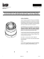
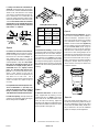
Astria Fireplaces MPD provides efficient heating solutions for your indoor and outdoor spaces, combining style with functionality. Equipped with a variable-speed fan and a convenient remote, it offers customizable warmth and comfort at your fingertips. Its compact size makes it ideal for smaller areas, allowing you to enjoy cozy ambience in any room or on your patio. With its energy-saving design, the MPD helps you save money on heating bills while still maintaining a comfortable temperature.
Astria Fireplaces MPD provides efficient heating solutions for your indoor and outdoor spaces, combining style with functionality. Equipped with a variable-speed fan and a convenient remote, it offers customizable warmth and comfort at your fingertips. Its compact size makes it ideal for smaller areas, allowing you to enjoy cozy ambience in any room or on your patio. With its energy-saving design, the MPD helps you save money on heating bills while still maintaining a comfortable temperature.


-
 1
1
-
 2
2
-
 3
3
-
 4
4
-
 5
5
-
 6
6
-
 7
7
-
 8
8


Astria Fireplaces MPD Instruction Sheet
- Category
- Fireplaces
- Type
- Instruction Sheet
Astria Fireplaces MPD provides efficient heating solutions for your indoor and outdoor spaces, combining style with functionality. Equipped with a variable-speed fan and a convenient remote, it offers customizable warmth and comfort at your fingertips. Its compact size makes it ideal for smaller areas, allowing you to enjoy cozy ambience in any room or on your patio. With its energy-saving design, the MPD helps you save money on heating bills while still maintaining a comfortable temperature.
Ask a question and I''ll find the answer in the document
Finding information in a document is now easier with AI
Related papers
Other documents
-
 TOA Electronics SSDVT-3530CNE User manual
-
Lennox LMDV-3530CNM User manual
-
 Lennox Hearth MPD-45 Series User manual
-
 Lennox Hearth MPDR-3328CPE-B User manual
-
Intertherm Fireplaces - Direct Vent Gas Installation guide
-
 TOA Electronics SSDVR-3328CNE User manual
-
-
Superior SDDV-40PM User manual
-
-
Superior Fireplaces DRT3000 Operating instructions


