Page is loading ...

Document no. 1.042.015.5n from firmware rel. 2.0 / hardware rel. 20
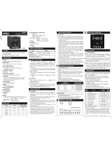
Power Analyser
UMG 508
Operating manual and
technical data
Art. no. 33.03.121 (UL)
Janitza electronics GmbH
Vor dem Polstück 1
D-35633 Lahnau
Support Tel. 0049 6441 9642-22
Fax 0049 6441 9642-30
e-mail: [email protected]
Internet: http://www.janitza.com
www.janitza.com

2
UMG 508
General 3
Goods-in Check 6
Description 8
Intended Use 8
Features 9
Measurement Method 10
GridVis network analysis software 11
Assembly 12
Place of Installation 12
Installation extradata 12
Front Board Cutout 12
Ethernet Connection 13
Fixing 13
Installation 14
Supply Voltage 14
Voltage Measurement 16
Current measurement 24
RS485 28
Ethernet 32
Digital outputs 34
Digital Inputs 36
Operation 38
Measurement value displays 39
"Home“ measurement value display 40
Select measurement value display 41
Call up additional information 42
Delete min/max values individually 43
List of transients 44
List of events 45
Configuration 46
Language 47
Communication 48
Measurement 50
Transients 56
Events 58
Display 60
System settings 62
Password 63
Delete minimum and maximum values 64
Delete power meters 65
Extensions 68
Initialization 71
Applying the supply voltage 71
Apply measurement voltage 72
Rotary field direction 72
Applying measurement current 73
Checking the power measurement 75
Checking communication 75
Service and Maintenance 81
Technical data 85
Dimensioned drawings 94
Measurement value displays overview 97
Connection example 100

3
UMG 508
General
Copyright
This handbook is subject to the legal regulati-
ons of copyright law protection and may not be
mechanically or electronically photocopied or
reprinted in full in or parts and, without the legal,
written permission of
Janitza electronics GmbH,
Vor dem Polstück 1,
D 35633 Lahnau, Germany,
may not be reproduced or further publication in
any other way.
Protected trademarks
All trademarks and the resulting rights belong to
the respective owners of the rights.
Disclaimer
Janitza electronics GmbH does not accept any
liability for errors or deficits in this handbook
and is not obliged to keep the contents of this
handbook updated.
Comments on the handbook
We welcome your comments. If anything in this
handbook seems unclear, please let us know
and send us an EMAIL to:

4
UMG 508
Meaning of Symbols
The following pictograms are used in this hand-
book:
Gefährliche Spannung!
Danger of death or risk of major injury.
Disconnect the system and device be-
fore beginning any work.
Protective ground connection.
Caution!
Please pay attention to the documenta-
tion. This symbol should warn against
possible dangers that can occur during
assembly, initialization and use.
m
c
Inductive.
The voltage lags the current
Capacitive.
The voltage lags the current.
CNote.

5
UMG 508
Application Information
Please read this operating manual and all other
publications that have to be consulted to work
with this product (particularly for installation,
operation or maintenance).
Please pay attention to all safety regulations and
warning information. If you fail to follow the in-
formation, it can result in personal damage and/
or damages to the product.
Any unauthorized change or use of this device
beyond the specified mechanical, electrical or
other operating limits can cause personal da-
mage and/or damage to the product.
Any such unauthorized change represents "mi-
suse" and/or "negligence" in the sense of gua-
rantee for the product and therefore makes the
guarantee covering possible consequential da-
mages void.
This device is to be exclusively operated and
maintained by a specialist.
Specialists are persons who, due to their rele-
vant training and experience, are capable of re-
cognizing risks and avoiding possible hazards
that can be caused when operating or servicing
the device.
When using the device, the necessary legal and
safety regulations should be considered additio-
nally for the respective application case.
Caution!
If the device is not operated according
to the operating manual, protection is
no longer ensured and the device may
cause dangers.
c
Cables with single wires must be provi-
ded with ferrules.
Only screw plugs with the same pole
number and the same type of const-
ruction can be plugged together.
m
m

6
UMG 508
The installation and initialization inst-
ructions also describe options that do
not belong to the scope of supply.
Goods-in Check
Correct and safe operation of this device is
subject to appropriate transportation, correct
warehousing, installation and assembly as well
as careful operation and maintenance. If it can
be assumed that safe operation without any
danger is no longer possible, the device must
be taken out of operation immediately and se-
cured against unintentional initialization.
Unpacking and packing must take place, with
the usual care without applying force and using
suitable tools. The devices must be checked for
perfect condition with visual tests.
It should be assumed that risk-free operation is
not possible if, for example:
• There is visible damage,
• it no longer works due despite the main sup-
ply being intact,
• has been subject to unfavorable conditions
(e.g. storage outside of the authorized climate
limits without adaptation to the room climate,
thawing etc.) over a longer period of time or
transport stresses (e.g. a fall from a height, in-
cluding without any visisble external damage
etc).
• Please check the delivered items for comple-
teness before starting with the installation of
the device. All supplied options and design versi-
ons are described on the delivery note.
All screw clamps that belong to the
scope of supply are attached to the
device.
C
C
C

7
UMG 508
Art.no. Description
13 10 539 Profibus plug, 9-pole DSUB, with integrated switchable terminating
resistors.
1)Refer to delivery note for article number.
Scope of Supply
Available accessories
Quantity Art.no. Description
1 52 21 xxx 1) UMG508
1 33 03 121 operating manual
1 51 00 116 CD with the following contents:
- "GridVis“ programming software,
- DEscription of functions, GridVis, UMG508,
- UMG508, GSD file "U5080C2C.GSD“ for Profibus DP V0
1 10 01 818 screw clamp, pluggable, 2-pole (auxiliary power)
1 10 01 847 screw clamp, pluggable, 5-pole (voltage measurement 1-4)
1 10 01 822 screw clamp, pluggable, 8-pole (current measurement 1-4)
1 10 01 810 screw clamp, pluggable, 6-pole (digital outputs)
2 10 01 809 screw clamp, pluggable, 5-pole (digital inputs)
1 08 01 505 2m patch cable, twisted, gray (connection UMG508-PC/Switch/Hub)
1 52 19 301 fixing clips

8
UMG 508
Description
Intended Use
The UMG508 is intended for measurements in
the building installation, on distributors, power
switches and bus bars.
Measurement voltages and measurement cur-
rents must come from the same network.
The UMG508 is suitable for installation in switch
boards with a fixed, weather-protected extrada-
ta.
The UMG508 can be used in 2, 3 and 4 supply
networks and in TN and TT networks.
The current measurement inputs of the UMG508
are connected using external ../1A or ../5A cur-
rent transformers.
The measurement in medium and high-voltage
networks generally takes place using current
and voltage transformers.
The UMG508 can be used in residential and in-
dustrial areas.
Measurement results can be displayed, saved
and read-out using serial interfaces for further
processing.

9
UMG 508
Features
• Front board installation, 144x144mm,
• Working temperature range -10°C .. +55°C,
• Colour graphic display 320x240, 256 colours, 6 keys,
• 8 digital inputs, 5 digital outputs,
• 16Bit A/transformer, data memory 256MByte Flash, SDRAM 32Mbyte,
• Continuous scanning of voltage and current measurement inputs with 20kHz,
• Frequency range of fundamental oscillation 40Hz .. 70Hz
• 4 voltage measurement inputs, 4 current measurement inputs,
• Measurement in TN and TT networks,
• RS485: Profibus DP/V0, Modbus RTU, Modbus-Master, BACnet (Option)
• Ethernet: Web-Server, EMAIL, BACnet (Option),TCP/IP, EMAIL (SMTP), DHCP-Client (BootP),
Modbus/TCP, Modbus RTU over Ethernet, FTP, ICMP (Ping), NTP, TFTP. BACnet (Option), SNMP.
• Detection of transients >50µs and storage with up to 16000 scanning points,
• Detection of more than 800 measurement values,
• Measurement of harmonics 1 to 40, for
- Uln, I, P (ref/supply) and
- Q (ind/cap),
• Programming own applications in Jasic.

10
UMG 508
Measurement Method
The UMG508 measures without any gaps and
calculates all effective values over a 200ms In-
terval.
The UMG508 measures the real effective value
(TRMS) of the voltages and currents applied to
the measurement inputs.
Operating Concept
You can program the UMG508 in several ways
and call up measurement values.
• Direct- on the device using 6 keys and the
display.
• Using the programming softwareGridVis.
• Using the UMG508 homepagefor devices
with an Ethernet interface.
• Using the RS485 with theModbus-protocol.
You can change and call up data with the help
of the Modbus address list (stored on the en-
closed data carrier).
Only operating the UMG508 using the integra-
ted display and the 6 keys is described in this
operating manual.
The GridVis programming software and the
homepage have their own "online assistance“.

11
UMG 508
GridVis network analysis software
The UMG508 can be programmed and read-
out with the GridVis network analysis software
included in the scope of supply. A PC must
be connected using a serial interface (RS485/
Ethernet) to the UMG508.
GridVis features
• Programming the UMG508.
• Configuration of recordings.
• Recordings read-out.
• Saving data in a database.
• Graphic presentation of measurement values.
• Programming specific applications for the cli-
ent.
PC UMG
508
Ethernet
Illu. Connection of a UMG508 to a PC using an
interface converter.
PC UMG
508
RS232
RS485
Interface
Converter
Illu. Connection of a UMG508 to a PC using
Ethernet.

12
UMG 508
Assembly
Place of Installation
The UMG508 is suitable for installation in fixed,
weather protected switch boards. Conducting
switch boards have to be grounded.
Installation extradata
In order to achieve sufficient ventilation, the
UMG508 has to be installed vertically. The clea-
rance has to be at least 50mm at the top and
bottom and 20mm at the side.
Front Board Cutout
Cutout size: 138+0.8 x 138+0.8 mm
Failure to maintain the minimum clea-
rances can destroy the UMG508 at
high environmental temperatures!
Wall
Airflow
Airflow
Ethernet
Connection
Illu. UMG508 installation extradata; view from
back.
m

13
UMG 508
Ethernet Connection
Patch Cable
Ethernet Connection
The UMG508's Ethernet connection is located
on the underside of the housing.
Depending on the bending radius of the Ether-
net cable and plug type, you must provide a
connection area beneath the UMG508.
The connection area beneath the UMG508
should not be less than 50 mm.
50 mm
Fixing
The UMG508 is fixed into the switch board with
two fixing clips that are each mounted on the
device at the top and bottom.
Fixing Clips

14
UMG 508
Installation
Protective Wire Connection
Use a ring cable lug for connecting the protecti-
ve wire to the UMG508.
Supply Voltage
A supply voltage is required to operate the
UMG508. The type and level of the necessary
supply voltage is noted on the label.
Before applying the supply voltage, make sure
that the voltage and the frequency match the
details on the label!
The auxiliary voltage has to be connected via an
UL/IEC approved fuse (1A Class CC) or a circuit
breaker (1A C.Char.)
Illu. Connection example; connection of supply
voltage to a UMG508.
Separator
Fuse
L1 N PEL3L2
Protective wire
cWarning - danger of death!
It is necessary for the protective wire
connection on the device to be con-
nected with the system grounding.
Connection point for
protective wire

15
UMG 508
- An isolator or circuit breaker must be
provided for the voltage supply in buil-
ding installation.
- The isolator must be attached near
to the device and must be easy for the
user to access.
- The switch must be marked as a se-
parator for this device.
-Voltages above the authorized voltage
range can destroy the device.
m
Warning!
The inputs for the supply voltage are
dangerous to touch!
c
Warning!
Please pay attention to the details on
the supply voltage provided on the
UMG508 label.
c

16
UMG 508
Illu. Basic circuit diagram, UMG508 in theTN-
network.
Voltage Measurement
Three-phase 4 conductor systems
The UMG508 can be used in three-phase 4 con-
ductor systems (TN, TT network) with a groun-
ded neutral wire. The bodies of the electrical
system are grounded.
Three-phase 3 conductor systems
The UMG508 is only suitable for use in IT net-
works with restrictions, because the measure-
ment voltage is measured against the housing
potential and the input impedance of the device
causes a leakage current against ground. The
leakage current can cause isolation monitoring
in IT networks to respond.
Connection variations with a voltage transfor-
mer are suitable for IT networks without any re-
strictions.
Illu. Basic circuit diagram, UMG508 in the IT net-
work without N.
600V 50/60Hz
DC
AC/DC
L2
L3
Auxiliary
power
Voltage measurement
4M
4M
4M
4M
V1 V3V2
4M
V4
System
grounding
Impedance
L1
UMG508
Vref
PE
347V/600V 50/60Hz
L2
L3
N
L1
N
L1
240V
50/60Hz
System
grounding
DC
AC/DC
Auxiliary
power
Voltage measurement
4M
4M
4M
4M
V1 V3V2 Vref
4M
V4
UMG508

17
UMG 508
Maximum nominal voltage of
the network
Maximum nominal voltage of
the network according to UL
UL-N / UL-L
66V / 115V
120V / 208V
127V / 220V
220V / 380V
230V / 400V
240V / 415V
260V / 440V
277V / 480V
347V / 600V
Illu. Table of suitable network nominal voltages
for the voltage measurement inputs according
to EN60664-1:2003.
Three-phase 4 conductor systems with
grounded neutral wire.
Nominal Voltages
Lists of the networks and their nominal network
voltages in which the UMG508 can be used.
UL-L
66V
115V
120V
127V
200V
220V
230V
240V
260V
277V
347V
380V
400V
415V
440V
480V
500V
577V
600V
Illu. Table of suitable network nominal voltages
for the voltage measurement inputs according
to EN60664-1:2003.
Ungrounded three-phase 3 conductor
systems.

18
UMG 508
Voltage Measurement Inputs
The UMG508 has 4 voltage measurement in-
puts (V1, V2, V3, V4).
Measurement category
The voltage measurement inputs are suitable for
measurements in networks in which overvolta-
ges in the measurement category 600V CATIII
can occur.
Frequency
The UMG508 requires the rated frequency for
measuring and calculating measurement values.
The UMG508 is suitable for measurements in
networks with a rated frequency in the range of
40Hz to 70Hz.
Illu. Connection example for voltage measure-
ment.
A connection diagram does not have
to be configured for the measurement
inputs V4 and I4.
C
L1 N PEL3L2
10A
(UL/IEC listed)

19
UMG 508
The following has to be considered when con-
necting the voltage measurement:
• A suitable separator is to be provided in order
to disconnect the UMG508 from the current
and voltage.
• The separator must be placed near to the
UMG508, labelled for the user and must be
easy to reach.
• Use for over current protection and circuit
breaker an UL/IEC approved fuse 10A Class
CC.
• The overcurrent protection device must have
a nominal value calculated for the short-cir-
cuit current at the connection point.
• Measurement voltages and measurement
currents must come from the same network.
Warning!
The voltage measurement inputs on the
UMG508 are dangerous to touch!
c
Warning!
The UMG508 is not suitable for measu-
ring DC voltages.
Warning!
Voltages that exceed the authorized
network nominal voltages must be
connected using a voltage converter.
c
Warning!
The voltage measurement inputs may
not be used for voltage measurement
in SELV circuits (Safety Extra Low Vol-
tage).
c
c

20
UMG 508
Connection diagrams, voltage measurement
L1
L2
L3
N
V1V2V3V4Vref
3p 4wu
L1
L2
L3
N
V1V2V3V4Vref
3p 4w
L1
L2
V1V2V3V4Vref
1p 2w
L1
L2
L3
N
3p 2i
L1
L2
L3
3p 2i0
L1
L2
1p 2i
I1I2I3I4
S1 S2 S1 S2 S1 S2 S1 S2
I1I2I3I4
S1 S2 S1 S2 S1 S2 S1 S2
I1I2I3I4
S1 S2 S1 S2 S1 S2 S1 S2
L1
L2
L3
N
3p 4w I1I2I3I4
S1 S2 S1 S2 S1 S2 S1 S2
L1
L2
L3
V1V2V3V4Vref
3p 3wu
L
L
L
L
N
3p 5w I1I2I3I4
S1 S2 S1 S2 S1 S2 S1 S2
L1
L2
L3
V1V2V3V4Vref
3p 3w
L
L
L
L
V1V2V3V4Vref
3p 5w
N
L1
L2
L3
N
V1V2V3V4Vref
3p 4wu
L1
L2
L3
N
V1V2V3V4Vref
3p 4w
L1
L2
V1V2V3V4Vref
1p 2w
L1
L2
L3
N
3p 2i
L1
L2
L3
3p 2i0
L1
L2
1p 2i
I1I2I3I4
S1 S2 S1 S2 S1 S2 S1 S2
I1I2I3I4
S1 S2 S1 S2 S1 S2 S1 S2
I1I2I3I4
S1 S2 S1 S2 S1 S2 S1 S2
L1
L2
L3
N
3p 4w I1I2I3I4
S1 S2 S1 S2 S1 S2 S1 S2
L1
L2
L3
V1V2V3V4Vref
3p 3wu
L
L
L
L
N
3p 5w I1I2I3I4
S1 S2 S1 S2 S1 S2 S1 S2
L1
L2
L3
V1V2V3V4Vref
3p 3w
L
L
L
L
V1V2V3V4Vref
3p 5w
N
/