Page is loading ...

12 x 12 Flat Top
Louvered Pergola
ASSEMBLY GUIDE
Ver 1.1-101415
Model: Camelot
www.newenglandarbors.com
OPTIONAL ACCESSORIES:
s"OLT$OWN"RACKET+ITs0RIVACY7ALLs0ERGOLA0LANTER
(4 for Pergola)

Table of Contents
2
12 x 12 Flat Top Louvered Pergola
3
12 x 12 Flat Top Louvered Pergola
INtroduCtION & OVerVIeW……………………………. . . . . . . . . . . . . . . . . . . . . . . . . . . . . . . . . . . . . . . . . . . . . . . .………. . . . . .
0erGOla MaterIals OVerVIeW………………………. . . . . . . . . . . . . . . . . . . . . . . . . . . …. . . . . . . . . . . . . . . . . . . . . . . . . . . . . . . . . . .
0erGOla MaterIals "reaKdoWN………………………. . . . . . . . . . . . . . . . . . . . . . . . . . . . . . . . . . . . .…. . . . . . . . . . . . . . . . . . . . . . .
0erGOla AdDITIONal MaterIals,Ist………………………………. . . . . . . . . . . . . . . . . . . . . . . . . . . . . . . . . . . . . . . . . . . . . . . . . .
7ood 0ost LaYout & INstallaTION for)NGroUNd ApplICaTION………………………………. . . . . . . . . . . . . . . . . . . . .
7ood 0ost LaYout & INstallaTION uSING"olt $oWN0ost "raCKets for CoNCrete or 7ood SurfaCe……………
VINYLColum
N AssembLY aND)NstallatION OVer 7ood 0osts………………………. . . . . . . . . . ………………….
MAIN Support "eam AssemblY…………………………. . . . . . . . . . . . . . . . . . . . . . . . . . . . . . . . . . . . . . . . . . . . . . . . . . . . . . . . . . . . . .
Rafter AssemblY……………………………………. . . . . . . . . . . . . . . . . . . . . . . . . . . . . . . . . . . . . . . . . . . . . . . . . . . . . . . . . . . . . . . . . .
MaIN3upport "eams & Rafter 0laCemeNt……………………………………. . . . . . . . . . . . . . . . . . . . . . . . . . . . . . . . . . . . . .
LouVer ASSEMBLY …………………………………………………………. . . . . . . . . . . . . . . . . . . . . . . . . . . . . . . . . . . . . . . . .
TurN"ar Holder INstallatIoN . . . . . . . .………………………………………. . . . . . . . . . . . . . . . . . . . . . . . . . . . . . . . . . . . . . . .
OperaTIONs …………………. . . . . . . ……………………………………… . . . . . . . . . . . . . . . . . . . . . . . . . . . . . . . . . . . . . . .
MODIFICaTION …………………………………………………………. . . . . . . . . . . . . . . . . . . . . . . . . . . . . . . . . . . . . . . . . . . . .
PAGE
4
5
6
7
8
9
10
11
13
15
www.newenglandarbors.com
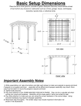
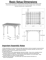
Top View
Front View
Side View
21
20
22
90 in
134 in
144 in
42 in
175 in
175 in
92.5 in
134 in
103.9 in

Introduction & Overview
3
12 x 12 Flat Top Louvered Pergola
Getting Started
FIRSTOFf, alloWUSto saYTHANKYou fORTHEINVestmeNt YOUHaVEMADEINONE
of oURFINe perGOLa KITs. THIs KItISDEsIGNed to be assembled AND INstalled
IdeallY bY tWo people WITH basICCarpeNtrYKNoWLEDGEaNd tools. $o NOT
attEMPTALONe, espECIALLYDUrINGTHEINSTALLaTIONSTAGe. SHOULDYOUDECIDEto
moderatELYMODIFYTHEDIMENSIONSOFYour perGOLAFrOMTHESTANDArd KITSIze,
ACIrCular saW WITH a sHarp fINe-tootHBlade Is all tHat IS Needed to CUt, sHOrteN
orMODIFYTHEVINYLCompoNENts.
7HENassemblINGCompONeNts plaCe oN a
NON-abrasIVe
surfaCe (IE: SHIPPINGbox) to aVoID sCratCHING. 7e reCom-
MENDA’ x 15’
area foRUNobstruCted assemblING. You SHould NOt Need to
use exCesSIVe forCe
WHEN
ASSEMBLINGANYCompONENts.
Planning & Preparing
THECamelot 0erGOLAIs made to staNDINDepeNdeNt of YourHome AND You
CaN
EITHERLOCatEITNEARYOURHOUSEORLETITSTANDALONEINTHEGArDEN. "YKeep-
ING
ITUNattaCHed from YoURHome You WIll NOT HaVe to deal WITH moVINGeXIS-
TING
GUTters or matCHINGEaVEHEIGHts. If YOUPLANtOBUILDYour perGOLACLOSE
to THEHOUse, please Keep tHEOUter extremITIEs of tHEperGola a mINImum of
4INCHESBACKFrom Your eaVes.
7Hat loOKS LIKe tHEtoUGHESt part oFTHIs projeCt Is aCtuaLLYTHEEASIESt,THe
GraCeful,SOLIDLOOKINGCOLUMNs. 7e’VEDESIGNEDTHESECOLUMNStOSIMPLYbe
SLIPped oVer treated 4x4 Wood pOSTSTHat arEEITHEREMbEDDEDINCONCrete or
DIreCTLYMOUNted to a CONCrete or Wood surfaCEUSINGOURbolt doWNBrACKets.
SEEPAGES,ANDfor morEDETAILs.
It ISCrItICal before You starTTHat You CoNSIder tHECUrreNt slope of eleVatIoN
WHere tHEperGOLaIs plaNNEDIFTHEre IS aNY. Also uTILItYORsprINKlerLINe
loCatIoNISIMportaNt tOIdeNtIFYPrIORto exCaVatINGHOLESIFNeCessarY.
YOUSHOULDALSOCHECKto VerIFY
loCALBUILDINGCodes, orDINANCes,NEIGHbour-
HOODCoVENANts,ORHEIGHt restrICTIONSrEGArDINGTHIStYpe of struCture.
Restriction of Use
This product is not designed to carry additional
weight loads such as swings, people or other
objects.
Please take the time to read this instruction
guide thoroughly prior to the construction
of your pergola. If you have any questions,
feel free to contact our technical dept by calling
1 800 282 9346,(Mon to Fri 8:00 A.M to 4:00 P.M.
EST).
(Camelot Pergola Shown)
www.newenglandarbors.com
Introduction & Overview

Camelot Pergola Materials Overview
4
12 x12 Flat Top Louvered Pergola
1
2
4
3
1. 0ost Caps (4)
2. MAINCOLUMN Tops (4)
3. 0ost TrIMS(8)
4.
Rafter & "eam $eCoratIVe END Caps
(20)
5. MAIN3UPport "eams (8)
6. "eam & Rafter JOINERS(10)
7. MAINCOLUMN"ottoms (4)
8.
Rafters
(12)
9.
/Ne 7aYvX “ INterNal7ood 0ost GuIdes
(4)
5
7
8
6
www.newenglandarbors.com
14
17
16
12
15
9
10.
LouVer TurN "ar
(1)
11.
TurN"ar
Holder (1) - Found in Box 7
12.
0re-assembled LouVer "ars
(RIGHt) - 7ITHLONGLouVer "ar (3)
13.
0re-assembled LouVer "ars
(Left) - 7ITHLONGLouVer "ar (3)
14.
Steel Holder "raCKets
(36)
15.
LouVer "oards
(84)
16.
0
re-assembled LouVer "ars - 7ITHSHOrt LouVer "ar (3)
17. 0
re-assembled LouVer "ars - 7ItH No LouVer "ar
(3)
10
11
13

11
7
6
2
9
16
3
10
Check Boxes (Total of 7) for These Contents
INTHe eVeNt of mISsINGORdefeCtIVe parts pleasECALLOURCUstomer serVICe
dept. at
1 800 282 9346
(Mon. to Fri. 8:00 AM to 4:00 PM EST).
1. 0ost Caps (4)
2. MAINCOLUMN Tops (4)
3. 0ost TrIMS(8)
4.
Rafter & "eam $eCoratIVE%NDCaps
(20)
5. MAIN3UPport "eams (8)
6. "eam & Rafter JOINERS (10)
7. MAINCOLUMN"ottoms (4)
8.
Rafters
(12)
9.
/Ne 7aYvX “ INterNal 7ood 0ost GUIDes
(4)
10.
LouVer HaNdle "ar
(1)
11.
0re-assembled LouVer "ars
(RIGHt) - 7ITHLONGLouVer "ar (3)
12.
0re-assembled LouVer "ars
(Left) - 7ITHLONGLouVer "ar (3)
13.
Steel Holder "rACKets
(36)
14.
LouVer "oards
(84)
15.
0
re-assembled LouVer "ars - 7ITHSHOrt LouVer "ar (3)
16. 0
re-assembled LouVer "ars - 7ITHNo LouVer "ar
(3)
Camelot Pergola Materials Breakdown
5
12 x 12 Flat Top Louvered Pergola
1
8
4
5
15
www.newenglandarbors.com
12
14
13
Not to Scale
Note the distance to
the first louver bracket

Pergola Additional Materials List
Hardware (in plastic bag)
NOTE: WE HAVE INCLUDED 10% EXTRA SCREWS
BEYOND WHAT IS IDENTIFIED BELOW.
All Screws Included with this Kit are Self-Auguring.
A. Tube of Vinyl Weld Glue (2)
B. 5/8” Self-Auguring Stainless Steel Screws (72)
(to lock Louver Assembly to Steel Holder Brackets
)
C.
1 1/2” Self-Auguring Stainless Steel Screws (40)
(for Beam and Rafter Joiners
)
D.
2 1/2” Self-Auguring Stainless Steel Screws (32)
(to lock the Main Column Bottom
and Tops to the Wood Posts )
E.
2 1/2“ Self-Auguring Stainless Steel Screws (2)
(to fasten Turn Bar Holder to post)
F.
4“ Self-Auguring Stainless Steel Screws (32)
(to lock Beams to the Posts)
G. 4”
Self-Auguring Stainless Steel Screws (40)
(to lock Rafters to the Beams)
H.
9” Stainless Steel Bolt Assembly with Nuts and Washers (4)
(to lock the Column Tops and Beams together)
I.
Turn Bar Holder (1) * Found in Box 7
Extra Materials You will Need
(Purchase separately from www.newenglandarbors.com or retailer of our products)
If Mounting Pergola on Concrete or Wood Deck
J.
4x4x8 Pressure-Treated Wood Posts (4)
(purchase at local building center)
K
. 4x4 Bolt Down Bracket Kit
(purchase from www.newenglandarbors.com or a
retailer of our products)
Refer to bolt down bracket instructions for hardware requirements,
as they pertain to your application:
If mounting pergola onto an existing concrete surface:
s1/2“ x 3 1/2” x 12“ Wood Shims (32)
s1/4” x 2 3/4“ Cement Screws - Countersunk Head (12)
s3/16” Concrete drill bit. Minimum 3“ long (1)
If mounting pergola onto a wooden/composite deck with AN ACCESSIBLE UNDERSIDE:
s1/2“ x 3 1/2” x 12“ Wood Shims (32)
s1/4” x ?“ Bolts and Nuts - Countersunk Head (12) (Length depends on blocking material)
s1/4” Washers (12)
s1/4” Wood drill bit. Minimum 3“ long (1)
If Mounting Pergola in Ground
L.
4x4x12 Pressure-Treated Wood Posts (4)
(purchase at local building center)
M.
Concrete Ready Mix (4) (purchase at local building center)
Rafter/ Beam Support (Required)
N.
2x6x12Pressure-Treated Boards for Beams and Rafters (10)
(purchase at
local building center)
Tools You Will Need
s,EVEL
s2UBBER-ALLET(AMMER
s4APE-EASURE
s3TRING,INE
s7OOD3TAKES(4)
(temporary support for string line)
s3TEP,ADDERS (2)
Not to Scale
6
12 x 12 Flat Top Louvered Pergola
www.newenglandarbors.com
C D E GFB HA
I
M
CONCRETE - Ready Mix
Purchase Separately
Purchase Separately
K
NJ
L
Purchase
Separately
Purchase
Separately
Purchase
Separately
s#ORDLESS$RILL
sv7OOD$RILL"IT
s#IRCULAR3AWWITH&INE4OOTH"LADE
s&RAMING3QUARE
s7RENCH3OCKET3ET

Wood Post Layout & Installation
for In-Ground Application
Measure and mark out the location of the pergola posts using
string line and temporary wood stakes. Diagonal distances must
be the same to ensure a square installation. Adjust string lines
accordingly. The inside corner of the string lines will be the post
location.
Please Note:
Should you decide to moderately modify the dimensions of your
pergola from the standard kit size, a circular saw with a sharp
fine-tooth blade is all that you need to cut, shorten or modify the
vinyl components.
1
This pergola can also be installed on a pre-existing wood or
concrete surface using our bolt down bracket system with
a 4x4 wood post (sold separate). See page eight for more details.
Post location and placement is the most critical step in the
overall installation process. Please double check for the
possibility of any underground utilities such as sprinkler, gas
or telephone lines.
STEP ONE
After you haVe determined where the posts will be located,
excAVate 10” diameter x 36” deep post holes.
After holes are dug and cleaned, place the 4x4 wood post into
a hole ensuring it’s leVel and square to string lines. The final post
height should be 102” out of the ground..
Fill the Vacant hole with pre-mixed concrete all the way to
within 3” of the top of the hole.
Once concrete has set, backfill 3” space with soil.
Repeat for all four posts.
Please Note:
Some 4x4 pressure treated posts can be larger than 3 1/2 x 3 1/2
square due to twisting or cracking. We have allowed a tolerance
for this in the internal one way and two way 4x4 wood post guides
(see page 8). However in extreme cases you may need to shave down
the top of the 4x4 wood post slightly to get the vinyl post started
over the wood post. Before installing your wood posts in the ground,
please check to confirm this and correct at this stage if necessary.
1
2
3
STEP TWO
Install Wood Supporting Posts Directly into the Ground
4
135 1/2 in.
344.2 cm
10”
36”
1
2
3”
3
7
12 x 12 Flat Top Louvered Pergola
Overhead View
191 5/8 in (486.7 cm.)
from corner of wood post to corner of wood post.
102 “ (Maximum)
Note:
Shown is a 11’-6” length of wood, and since
the 4x4 Pressure Treated wood comes in
12’ lengths, do one of the following:
a. Cut the wood down to 11’-6”
b. Dig 42” deep holes instead of 36”
135 1/2 in.
344.2 cm
www.newenglandarbors.com

Wood Post Layout & Installation
Using Bolt Down Brackets
for Concrete or Wood Surface
Measure and mark out the location of the bolt down brackets’
bottom of flange using string or chalk line.
Diagonal distances must
be the same to ensure a square installation. Adjust string lines
accordingly.
The inside corner of the string lines will be the corner
of the bottom flange.
Mark out the location of bolt down brackets using the base of
the bracket accordingly.
Using a 3/16” masonry drill bit, drill 3“ deep holes
to allow installation of 2 3/4” concrete screws. (Not included)
Proceed to install three 2 3/4” concrete screws into the bottom
base of the bolt down bracket.(Not included)
Please Note:
Concrete patios generally have sloped surface for water run-off.
If this is the case, when you secure the bolt down bracket to the
concrete, the bracket may be at an angle. This can be corrected
for level using galvanized steel washers (not provided), acting
as shims underneath the base to level - VERY IMPORTANT OR
PERGOLA BEAMS
AND
RAFTERS WILL NOT BE LEVEL.
1
OPTIONAL STEP
2
3
2
3
With the four post brackets installed plumb, proceed to set
the 4x4x8’ wood post in place. Secure using the wood screws
included in the kit.
Repeat for all 4 posts.
Please Note:
Some 4x4 pressure treated wood posts can be larger than 3 1/2 x
3 1/2 square due to twisting or cracking. We have allowed a
tolerance for this in the post brackets and the internal one way and
two way 4x4 wood post guides. However in extreme cases, you
may need to shave down the end of your 4x4 wood post slightly
to allow access.
In order to create a snug fit between the wood posts and the inner
CAVITYOFTHEVINYLPOSTSITWILLBENECESARYTOhBUILDOUTvTHEX
posts near the bottom and the top using 1/2” x 3 1/2” x 12” shims.
Follow instructions as illustrated.
5
5
4
4
Marker
8
12 x 12 Flat Top Louvered Pergola
3“ (Deep)
www.newenglandarbors.com
6
6 in
72 in
6
,EVEL
Shims to
“build out”
the 4x4 posts
on all four
sides
2
Marker
1
* Orientate brackets
accordingly to reduce
offset motion of posts.
(direction of arrows
denote flange
opening)
*
*
*
*
134 3/8 in
341.3 cm
134 3/8 in
341.3 cm
190 in (482.7 cm)
From corner of bracket
(Bottom of flange)
to corner of bracket

Vinyl Column Assembly & Installation
Over Wood Posts
9
12 x 12 Flat Top Louvered Pergola
1
Using thEVInyl weld glue, insert the One Way 4”x4” Internal
Wood Post Guide in the one end of the main column posts.
This step is only applicable if your wood 4x4 post are embedded
into the ground. If your pergola is going to be installed on
wood or concrete surface, please dispose of these four pieces.
Using a step ladder, guide the bottOMVInyl columns oVer the
wood 4x4 posts
.
Using a step ladder guide the tOPVInyl columns oVer the
wood 4x4 posts.
Please Note:
Ensure that predrilled holes at top of column are orientated
correctly for future beam and rafter placement. See diagram
at top of next page.
3a - If you also purchased base moldings (sold separately), they
should be inserted at this stage.
Connect the bottom and toPVInyl column by usinGVInyl weld
and sliding together.
Please Note: Vinyl Weld Glue has about a
sixty second cure time and about a
20 minute dry time.
Slide the top and bottom post trim into position. Use the bottom
post trim to coVer the joint on
the column. Slide the
top post trim
into approximate position ±3” below the
hole in the toPVinyl column
assembly.
If required, adjust post heights accordingly to ensure future
leVel
installation of beams and rafters as necessary. If slope is seVere
causing a height difference between the posts, you may need
to trim down the bottom of two or more of yourVinyl
columns as necessary.
SecurETHEVinyl columns to the wood posts using 4 – 2 1/2“
self-auguring stainless steel screws at 8” up from the base
of the posts, and 4 – 2 1/2” self-auguring stainless steel screws
just aboVe the trim cap as illustrated. This will preVent possible
uplift during high winds,
etc.
If base moldings are installed, place screws aboVe the base
moldings.
Using the predrilled hole as a template, driVe a 1/2” hole
through the wood post. Make sure to drill straight through
to the hole on the opposite side of the post.
1
2
4
STEP THREE
5
6
7
7a
5
7
7a
*Ensure that predrilled holes at top of
column are orientated correctly for
future beam and rafter placement.
3
3
*
2
4
3a
8

Main Support Beam Assembly
1
1
2
STEP FOUR
10
12 x 12 Flat Top Louvered Pergola
At this stage, the columns should be properly
installed as per the following illustration,
with the columns 134” in. (340.4 cm) apart.
Also, notice that the holes at the top of each
post should be facing the same direction.
www.newenglandarbors.com
134in.
340.4 cm.
134 in.
340.4 cm.
Critical Note:
Note the location of the pre-drilled hole on main support beams
as pictured aside. These holes will align with the hole on the posts.
Both ends of main support beam section should extend approximately
6” over the pressure treated wood.
Insert one 2x6x12’ pressure treated wood into a main support beam
section followed by the joiner and another main support beam
section.
Glue and attach the DecoratiVe End Caps onto the ends as shown.

11
12 x 12 Flat Top louvered Pergola
Main Support Beam Assembly
Using four 1 1/2” screws provided, fasten the Beam Joiners,
Main Support Beam, and Wood together as shown.
Now that the wood is secured in place, use the predrilled holes
as templates and drill 1/2” holes through the wood as shown.
Make sure to drill straight through to the other side of the main
support beam.
Repeat for all four main support beams.
3
4
5
www.newenglandarbors.com
3
4
Rafter Assembly
1
STEP FIVE
To accomodate the notches on the rafters, first the wood inserts
must be notched out as shown below:
Six will be needed.
7 in (min)
3½ in
144 in
3½ in
7 in (min)

12
12 x 12 Flat Top louvered Pergola
Rafter Assembly
Insert one of the notched 2x6x12 pressure treated wood into a beam
section follow by the joiner and another beam section. Make sure the
notch is at the bottom as shown.
Glue and attach the Decorative End Caps onto the ends as shown.
Using four 1 1/2” screws provided, fasten the Rafter Joiners,
Rafters, and Wood together as shown.
Repeat for all six rafters.
2
3
4
5
www.newenglandarbors.com
3
4
Note:
Ensure the wood insert is not
protruding into the notched
area of the Rafter.

Main Support Beams & Rafter Placement
13
12 x 12 Flat Top Louvered Pergola
1
1
2
3
STEP SIX
Using a helper and two ladders proceed to complete the
following steps:
Raise one Main Support Beam Assembly at a time and insert
the Bolt Assembly into the holes to hold into place as shown.
Some force may be required to get the bolt through.
Do not tighten the nuts until all four beams are in place,
instead, simply hand-tighten them.
Once all four main suport beams are in position, use two
wrenches to lock the main support beams into place.
Fasten the main support beams onto the Posts using the 4” screws
provided (8 screws per post).
Place the rafters onto the main support beams as shown.
Space the middle two rafters 42” apart (Critical for louver placement)
2
3
www.newenglandarbors.com

Main Support Beams & Rafter Placement
14
12 x 12 Flat Top Louvered Pergola
Fasten the Rafters to the Posts using the 4” screws provided
(4 per post).
Fasten a 4” screw at each intersection where the Beams
and Rafters intersect as shown. 24 screws will be needed.
4
5
www.newenglandarbors.com
4
5
5
*Important: Make sure the distances between rafters are 42”.

Louver Assembly
15
12 x 12 Flat Top Louvered Pergola
This kit contains four different pre-assembled Louver Bars as shown
below and aside:
3 x Pre-Assembled Louver Bars (plain)
6 x Pre-Assembled Louver Bars with Long Louver Bar*
3 x Pre-Assembled Louver Bars with Short Louver Bar
*) There are two variations of Louver Bar Assemblies with Long Louver Bar.
Identify and layout the twelve louver bars assembly as shown below:
1
STEP SEVEN
6 x Pre-Assembled Louver Bars (plain)
Pre-Assembled Louver Bars with Long Louver Bar
Pre-Assembled Louver Bars with Short Louver Bar
Note:
The short louver bar assembly will be
packaged as such. You will need to
remove these two nuts and re-
position the short louver bar.
Note:
Reposition the short louver bar as shown but
do not bolt to the adjacent louver assembly at this point.
Important ! : the holes on the louver bars are offset. ensure
the holes are at the bottom as shown.
Note the distance to the first bolt;
the larger gap would go at the outside whereas
the smaller gap would go towards the middle bar assembly.
www.newenglandarbors.com
Ensure all brackets are facing
the same direction.
Note the difference in distance to the first Louver Bracket
Do not re-attach nuts

3
16
STEP EIGHT
12 x 12 Flat Top Louvered Pergola
Insert the Louver Boards one by one. Make sure each board is
inserted completely into the brackets.
Attach the matching Pre-assembled Louver Bar. Pressure fit
the boards one by one.
Repeat for all six sub-sections. At this point, you should have
three full sections of Louvers as shown below:
Louver Assembly
2
2
www.newenglandarbors.com
3
The ends of the louver bars with large
space should be at the same end.
4
Do not attach with nuts at this point
Ensure that the holes in the louver
holder brackets are all on top of the
louver bars assembly

Louver Assembly
17
12 x 12 Flat Top Louvered Pergola
Place twelve Steel Holder Brackets as shown below and care-
fully lower the Louver assembly onto the steel brackets.
Do not screw the Steel Holder Brackets in place at this point.
Fasten the Short Louver Bar using two nuts as shown.
Do not over tighten.
You will need to raise the middle section momentarily
to do this step.
5
www.newenglandarbors.com
Steel Holder Brackets
6
6
Note: check that the holes are closer to
the bottom as shown.
Install in order (one row at a time)

18
12 x 12 Flat Top Louvered Pergola
Slide the Steel Holder Brackets to a spot which will not
interfere with the operations of the louvers. ‘Open’ and
‘Close’ the louvers to test and make sure the steel
brackets are not constraining the operation.
From the top, fasten the steel brackets in place using
5/8” screws. A total of 12 screws will be needed.
Repeat for the underside of the steel brackets.
Another 12, 5/8” screws will be needed.
Louver Assembly
7
www.newenglandarbors.com
8
8
7
Bottom View
9
9

Louver Assembly
19
12 x 12 Flat Top Louvered Pergola
Repeat for other two rows.
Place the Post Caps onto the posts.
10
www.newenglandarbors.com
11
11
10

Turn Bar Holder Installation
1
1
2
STEP EIGHT
20
12 x 12 Flat Top Louvered Pergola
www.newenglandarbors.com
The Turn Bar Holder is packaged in box 7 kit and is
designed to provide a place to keep the Turn Bar when not in use.
Pick a location that is easily accessible and out of the way of the
louvers operation. The post is recommended as the 2 1/2” screws
are used to protrude into the wooden post, providing a secure
mounting support.
Mount with the slot on the top and closer to the post as shown.
Fasten with two 2 1/2” screws provided.
Hang the Turn Bar as shown.
3
2
Slot on the top and
closer to the post.
3
/