Page is loading ...

www.wearevita.com
10x10 Round Post Louvered Pergola
ASS E M B LY GUIDE
Model:
Preston
Ver 1.6 June 7 2021
211 Campbell St Sarnia,
Ontario N7T 2G6

Pergola Installation
Tools you will need.
cordless drill with #2 philips bit
1/2 x 6” wood chisel / paddle bit
rubber mallet or HAMMER
level and square
string line & Stakes
step ladder (2)
jig saw or circular saw
ratchet with 1/2” socket
tape measure
shovel
* premix concrete / cement
* (for in-ground installation)
+

Table of Con tents
2
10 x 10 Round Post Louvered Pergola
3
10 x 10 Round Post Louvered Pergola
Introduction & Overview……………………………. . . . . . . . . . . . . . . . . . . . . . . . . . . . . . . . . . . . . . . . . . . . . . . .………. . . . . .
Pergola Materials Overview………………………. . . . . . . . . . . . . . . . . . . . . . . . . . . …. . . . . . . . . . . . . . . . . . . . . . . . . . . . . . . . . . .
Pergola Materials Breakdown………………………. . . . . . . . . . . . . . . . . . . . . . . . . . . . . . . . . . . . .…. . . . . . . . . . . . . . . . . . . . . . .
Pergola Additional Materials List………………………………. . . . . . . . . . . . . . . . . . . . . . . . . . . . . . . . . . . . . . . . . . . . . . . . . .
Wood Post Layout & Installation for In-Ground Application………………………………. . . . . . . . . . . . . . . . . . . . .
Wood Post Layout & Installation using Round Post Brackets for Concrete or Wood Surface ………………
Vinyl Column Assembly and Installation Over Wood Posts………………………. . . . . . . . . . ………………….
Main
Support Beam Assembly…………………………. . . . . . . . . . . . . . . . . . . . . . . . . . . . . . . . . . . . . . . . . . . . . . . . . . . . . . . . . . . . . .
Rafter Assembly……………………………………. . . . . . . . . . . . . . . . . . . . . . . . . . . . . . . . . . . . . . . . . . . . . . . . . . . . . . . . . . . . . . . . . .
Main Support Beams & Rafter Placement……………………………………. . . . . . . . . . . . . . . . . . . . . . . . . . . . . . . . . . . . . .
Louver Assembly …………………………………………………………. . . . . . . . . . . . . . . . . . . . . . . . . . . . . . . . . . . . . . . . .
Turn Bar Holder Installation . . . . . . . .………………………………………. . . . . . . . . . . . . . . . . . . . . . . . . . . . . . . . . . . . . . . .
Operations …………………. . . . . . . ……………………………………… . . . . . . . . . . . . . . . . . . . . . . . . . . . . . . . . . . . . . . .
Modification …………………………………………………………. . . . . . . . . . . . . . . . . . . . . . . . . . . . . . . . . . . . . . . . . . . . .
PAGE
4
5
6
7
8
12
13
14
16
18
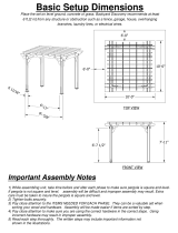
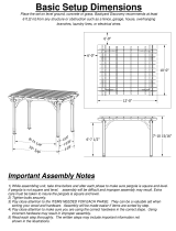
Top View
Front View
Side View
25
24
26
Wood Post Installation using Round Post Brackets onto a wood deck with an accessible underside . . . . . . .
10
87 1/4 in [222 cm]
89 3/4 in [228 cm]
115 in [292 cm]
115 in [292 cm]
121 in [307 cm]
109 in [277 cm]
109 in [277 cm]
121 in [307 cm]
96 1/8 in [244 cm]
151 in [384 cm]
151 in [384 cm]
34 in [86 cm]

Intro duc tion & O ver view
3
10 x 10 Round Post Louvered Pergola
Getting Started
First off, allow us to say thank you for the investment you have made in one
of our fine pergola kits. This kit is designed to be assembled and installed
ideally by two people with basic carpentry knowledge and tools. Do not
attempt alone, especially during the installation stage. Should you decide to
moderately modify the dimensions of your pergola from the standard kit size,
a circular saw with a sharp fine-tooth blade is all that is needed to cut, shorten
or modify the vinyl components.
When assembling components place on a
non-abrasive
surface (ie: shipping box) to avoid scratching. We recom-
mend a 15’ x 15’
area for unobstructed assembling. You should not need to
use excessive force
when
assembling any components.
Planning & Preparing
The Preston Pergola is made to stand independent of your home and you
can
either locate it near your house or let it stand alone in the garden. By keep-
ing
it unattached from your home you will not have to deal with moving exis-
ting
gutters or matching eave heights. If you plan to build your pergola close
to the house, please keep the outer extremities of the pergola a minimum of
4 inches back from your eaves.
What looks like the toughest part of this project is actually the easiest, the
graceful, solid-looking columns. We’ve designed these columns to simply be
slipped over treated 4x4 wood posts that are either embedded in concrete or
directly mounted to a concrete or wood surface using our mounting bracket kit
See pages 7, 8 and 9 for more details.
It is critical before you start that you consider the current slope of elevation
where the pergola is planned - if there is any. Also utility or sprinkler line
location is important to identify prior to excavating holes if necessary.
You should also check to verify
local building codes, ordinances, neighbour-
hood covenants, or height restrictions regarding this type of structure.
Restriction of Use
This product is not designed to carry additional
weight loads such as swings, people or other
objects.
Please take the time to read this instruction
guide thoroughly prior to the construction
of your pergola. If you have any questions,
feel free to contact our technical dept by calling
1 800 282 9346,(Mon to Fri 8:00 A.M to 5:00 P.M.
EST).
Intro duc tion & Over view

Pergola Materials Overview
4
10 x 10 Round Post Louvered Pergola
1
2
4
3
6
10
11
7
12
1. Post Caps (4) - 10095
2. Main Column Tops (4) - 11142
3. Round Post Adapter (4) - 11143
4.
Round Post Top Trim
(4) - 11136
5. Round Post Trim (4) - 11138
6. Main Column Bottoms (4) - 11144
7.
Round Post Base Trim (4) - 11139
8.
Rafter & Beam Decorative End Caps
(20) - 10829
9. Main Support Beams (8) - 10931
10.
Rafters (12) - 10934
13
5
13.
Round Post Louver Turn Bar Holder (1) - 60081 - Found in Box 7
14.
Pre-assembled Louver Bars (Right) - With Long Louver Bar (3) - 10936
15.
Pre-assembled Louver Bars (Left) - With Long Louver Bar (3) - 10945
16.
Steel Holder Brackets (36) - 10937
17.
Louver Boards (72) - 10938
18.
P
re-assembled Louver Bars - With Short Louver Bar (3) - 10939
19. P
re-assembled Louver Bars - With No Louver Bar (3) - 10940
11. Beam & Rafter Joiners (10)
- 10820
12.
Louver Turn Bar (1) - 10935
8
9
16
19
18
14
17
15

14
6
11
3
19
5
12
5
10 x 10 Round Post Louvered Pergola
1
10
8
9
18
15
17
16
Not to Scale
Note the distance to
the first louver bracket
1.
Pergola Materials Breakdown
Check Boxes (Total of 8) for These Contents
In the event of missing or defective parts please call our customer
service
dept. at
1 800 282 9346
(Mon. to Fri. 8:00 AM to 5:00 PM EST)
1. Post Caps (4) - 10095
2. Main Column Tops (4) - 11142
3. Round Post Adapter (4) - 11143
4.
Round Post Top Trim
(4) - 11136
5. Round Post Trim (4) - 11138
6. Main Column Bottoms (4) - 11144
7.
Round Post Base Trim (4) - 11139
8.
Rafter & Beam Decorative End Caps
(20) - 10829
9. Main Support Beams (8) - 10931
10.
Rafters (12) - 10934
2
4
7
13.
Round Post Louver Turn Bar Holder (1) - 60081- Found in Box 7
14.
Pre-assembled Louver Bars (Right) - With Long Louver Bar (3) - 10936
.51
Pre-assembled Louver Bars (Left) - With Long Louver Bar (3) - 10945
16.
Steel Holder Brackets (36) - 10937
17.
Louver Boards (72) - 10938
18.
P
re-assembled Louver Bars - With Short Louver Bar (3) - 10939
19. P
re-assembled Louver Bars - With No Louver Bar (3) - 10940
11. Beam & Rafter Joiners (10) - 10820
12.
Louver Turn Bar (1) - 10935
13
A
C
B
D

Pergola Additional Materials List
Hardware
(in plastic bag)
All Screws Included with this Kit are Self-Auguring.
A. Tube of Vinyl Weld Glue (2) - 20000
B. 5/8” (16mm) Stainless Steel Screws (72) - 20016
(to lock Louver Assembly to Steel Holder
Brackets
)
C. 5/8” (16mm) Stainless Steel Screws (16) - 20016
(to lock the Round Post Adapter to the Posts
)
D.
1 1/2” (38mm) Stainless Steel Screws (40) - 20005 -
(for Beam and Rafter Joiners
)
E.
2 1/2“ (64mm) Stainless Steel Screws (18) - 20009-1 -
(to fasten Turn Bar Holder to post)
F.
4“ (102mm) Stainless Steel Screws (32) - 20006 -
(to lock Beams to the Posts)
G. 4” (102mm)
Stainless Steel Screws (40) - 20006 -
(to lock Rafters to the Beams)
H.
9” (229mm) Stainless Steel Bolt Assembly with Nuts and Washers (4) - 20035 -
(to lock
the Column Tops and Beams together)
Extra Materials You will Need
(Purchase separately from www.wearevita.com or a retailer of our products) If
Mounting Pergola on Concrete or Wood Deck
I.
4x4x8 (10x10x250cm) Pressure-Treated Wood Posts, cut down to 94“ (239cm) (4)
(purchase
at local building center)
*IMPORTANT NOTE*
Most commercially available pressure treated 4x4 posts are milled to 3 1/2” x 3 1/2“ (8.9x8.9cm).
The wood posts cannot exceed 3 5/8” x 3 5/8“ (9.2x9.2cm) square in order to fit inside the round post inner
channels.
II. Round Post Bracket Kit
(purchase from www.wearevita.com or a retailer of our products)
Included in the
Round Post Bracket Kit: - Galvanized Steel Brackets (4)
- #8 x 1 1/2” (4x38mm) Wood Screws (4)
- 5/16 x 3“ (8x76.2mm) Lag Screws (12)
Refer to the Bracket Kit instructions for hardware requirements, as they pertain to your application:
If mounting pergola onto an existing concrete surface:
• 3/8” x 3“ (6x76.2mm) Concrete Sleeve Anchors - (16)
• 5/16” (8mm) Concrete drill bit. Minimum 3“ (76mm) long (1)
If mounting pergola onto a wooden/composite deck:
• 5/16” x ?“ (8x?mm) Lag Bolts (16) (Bolt length depends on thickness of deck)
• 5/16” (8mm) Washers (32)
• 9/64” (3.5mm) Wood drill bit. Minimum 3“ (76mm) long (1)
If mounting pergola onto a wooden/composite deck with AN ACCESSIBLE UNDERSIDE:
• 5/16” x ?“ (8x?mm) Bolts and Nylon-Insert Lock Nuts (16) (Bolt length depends on blocking material)
• 5/16” (8mm) Washers (32)
• 5/16” (8mm) Wood drill bit. Minimum 3“ (76mm) long (1)
• 2x10” (5.1x25cm) Wood Blocks (4) to be secured between the deck
joists, to provide adequate support for the pergola posts.
If Mounting Pergola in Ground
K.
4x4x12 (10x10x365cm) Pressure-Treated Wood Posts (4)
(purchase at local
building center)
L.
Concrete Ready Mix (4)
(purchase at local building center)
Rafter/ Beam Support (Required)
M.
2x6x10 (5x15x305cm) Pressure-Treated Boards for Beams and Rafters (10)
(purchase at local building center)
Not to Scale
6
10 x 10 Round Post Louvered Pergol
a
D E F G
CB
HA
L
CONCRETE - Ready Mix
Purchase Separ
ately
Purchase Separately
J
MI K
Purchase
Separ
ately
Purchase
Separately
Purchase
Separately
F

Wood Post Layout & Installation
for In-Ground Application
Measure and mark out the location of the pergola posts using
string line and temporary wood stakes. Diagonal distances must
be the same to ensure a square installation. Adjust string lines
accordingly. The inside corner of the string lines will be the post
location.
Please Note:
Should you decide to moderately modify the dimensions of your
pergola from the standard kit size, a circular saw with a sharp
fine-tooth blade is all that you need to cut, shorten or modify the
vinyl components.
1
This pergola can also be installed on a pre-existing wood or
concrete surface using our Round Post Ground Bracket Kit
with a 4x4 wood post (sold separate). See page eight for more
details.
Post location and placement is the most critical step in the
overall installation process. Please double check for the
possibility of any underground utilities such as sprinkler, gas
or telephone lines.
ST EP ONE
111 1/2 in.
283.2 cm
7
10 x 10 Round Post Louvered Pergola
157 11/16 in (400.5 cm.)
from corner of wood post to corner of wood post.
111 1/2 in.
283.2 cm
After you have determined where the posts will be located,
excavate 10” (25.4 cm) diameter x 36” (91.4 cm) deep post holes.
After holes are dug and cleaned, place the 4x4 (9x9cm) wood post
into a hole ensuring it’s level and square to string lines. The final post
height should be 94” (239 cm)out of the ground.
Fill the vacant hole with pre-mixed concrete all the way to
within 3” (7.6 cm) of the top of the hole.
Once concrete has set, backfill 3” (7.6 cm) space with soil.
Repeat for all four posts.
Please Note:
Some 4x4 pressure treated posts can be larger than 3 1/2 x 3 1/2
square due to twisting or cracking. We have allowed a tolerance
for this in the round post, however, in extreme cases you may need
to shave down
the top of the 4x4 wood post slightly to get the vinyl
post started
over the wood post. Before installing your wood posts in
the ground,
please check to confirm this and correct at this stage if
necessary.
1
2
3
ST EP T WO
Install Wood Supporting Posts Directly into the Ground
4
10”
25.4cm
36”
91.4 cm
1
2
3”
(7.6 cm)
3
94 “ (239 cm) Maximum
Note:
Shown is a 11’-6” (350 cm) length of wood, and
since the 4x4
(9x9cm)
Pressure Treated wood
comes in 12’ (365 cm) lengths, do one of the
following:
a. Cut the wood down to 11’-6” (350 cm)
b. Dig 42” (107 cm) deep holes instead of 36”
(91.4 cm)
Overhead View

Wood Post Layout & Installation
Using Round Post Bracket Kit
for Concrete or Wood Surface
Measure and locate the centre of the wood post. Pre-drill a 1/16”
[1.5mm] hole, about 1 1/2” (38mm] deep as shown.
Using the small screw provided with the ground bracket kit,
fasten the bracket to the bottom of the post as shown.
Position the ground bracket so that it is square to the wood
post and pre-drill 3, 5/16” [8mm] holes for the lag bolts as shown.
The holes should be approximately 3” [75mm] deep.
Using a socket wrench, fasten the 3 lag bolts supplied with the
kit as shown.
1
OPTIONAL STEP
2
3
4
8
10 x 10 Round Post Louvered Pergola
Note: for additional information on the Round Post Bracket Kit
installation, refer to the Round Post Bracket Kit instructions.
1
4
3
2
Make sure wood post
is square to bracket.
4”x4“x94” (10x10x239cm)
Note: Easiest way to measure and mark
the center of the post is to draw
an ‘x’ through the diagonals as
shown.

9
10 x 10 Round Post Louvered Pergola
107 in [271.8 cm]
107 in [271.8 cm]
151 5/8 in [385.1 cm]
From edge of bracket (bottom of plate)
to edge of bracket.
Measure and mark out the location of the ground brackets plate
using string or chalk line. Diagonal distances must be equal to ensure
a square installation. Adjust string lines accordingly.
The inside corner of the string lines will be the corner of the plate.
Mark out the location of brackets using the base plate of the bracket
accordingly.
Depending on where the pergola will be installed, you may need
sleeve anchors if installing on a concrete surface, or lag screws
if installing on a wood platform (deck). Refer to page 6 for hardware
recommendations.
Mounting hardware is not included in the Round Post Bracket Kit.
Following the instructions supplied with the hardware, proceed
to install four fasteners into each the base plate of the bracket.
Please Note:
Concrete patios generally have sloped surface for water run-off.
If this is the case, the ground bracket may be at an angle. This can
be corrected for level using galvanized steel washers (not provided),
acting as shims underneath the ground bracket
VERY IMPORTANT OR PERGOLA BEAMS AND RAFTERS WILL NOT BE LEVEL.
5
OPTIONAL STEP
6
7
5
8
Washer(s) as required.
7
8
8
Sleeve
Anchor
Lag Screw

10
10 x 10 Round Post Louvered Pergola
Wood Post Installation using Round
Post Bracket Kit onto a wood/composite
deck with an accessible underside
Locate the position of your bracket and mark the four corner holes.
Measure the distance between your joists and fasten a 2x10
(5.1x25cm) wood support directly below where the bracket
is to be installed. This will give the surface mount additional
strength.
Drill four 5/16” (8mm) diameter holes through the deck and
support.
Fasten the bracket as shown using the hardware listen on
page 6.
1
OPTIONAL STEP
2
3
4
2
4
3
1
2x10 (5.1x25cm) Wood Support
Joist
Deck
Measure
Fasten Wood Support in betwen joists
Fasten bolts with wrench

11
10 x 10 Round Post Louvered Pergola
Vinyl Column Assembly & Installation
Over Wood Posts
With a helper and a ladder, place the round post over the wood
post as shown.
Apply a small bead of glue around the base as shown,
approximately 4” (10cm) from the ground.
Slide the Round Post Base Trim over and down the post as
shown. Hold the base trim in place for about 20 seconds to
allow the vinyl glue to set.
NOTE: the Base Trim and ground bracket /wood post
should be square to each other.
Slide the Round Post Trim followed by the Round Post Top Trim
as shown. Let the two parts slide down for now as they will be
glued in place in later steps.
Attach the Round Post Adapter onto the top of the post and
fasten in place with 4, 5/8” (16mm) screws as shown.
Apply a small amount of glue to the inside of the Post Top Trim
where it would come in contact with the Post Adapter as shown.
Slide the Post Top Trim in place and hold for 20 seconds, allowing
the glue to set.
Apply a small amount of glue to the outside of the post where you
would like the Round Post Trim to be located (shown is 3” - 7.6cm)
Slide the Post Trim in place and hold for 20 seconds.
1
STEP T HREE
2
3
6
5
4
7
9
8
1 2 43
5 96 7 8

Vinyl Column Assembly & Installation
Over Wood Posts
Slide the Main Column Top over the Post Adapter as shown.
NOTE: Do not glue the Column Top at this point.
Note the location of the hole(s) on the Column Top and compare
it to the overall layout of your pergola. The direction in which the
holes face will determine the placement of the beams, rafters, and
louvers.
With a pencil, make a centre mark through the hole onto the
wood post.
Remove the Column Top and drill a 1/2” (13mm) hole through the
wood post as shown.
Replace the Column top and visually check that the hole is
completely drilled through.
Apply a small amount of glue to the inside of the Column Top
as shown and place the Post Cap as shown.
To secure the Column to the wood post, fasten 4, 2 1/2” (64mm)
screws through the column into the wood post approximately
8” (20cm) from the ground as shown.
1
STEP T HREE
2
5
4
3
6
1
2
3
54 6
8”
(20cm)
12
10 x 10 Round Post Louvered Pergola

STEP FOUR
At this stage, the columns should be properly
installed as per the following illustration,
with the columns 109” in. (276.9 cm) apart.
Also, notice that the holes at the top of each
post should be facing the same direction.
106 1/8 in.
269.6 cm.
109 in.
276.9 cm.
110 in. (279.4 cm.)
Between Faces
109 in. (276.9 cm.)
Between Tangent Surfaces
106 1/8 in. (269.6 cm.)
Between Post Base Trims
13
10 x 10 Round Post Louvered Pergola
Main Support Beam Assembly
1
1
2
Critical Note:
Note the location of the pre-drilled hole on beams as pictured
aside. These holes will align with the hole on the posts.
Both ends of beam section should extend approximately 6” over
the pressure treated wood.
Insert one 2x6x10’ pressure treated wood into a main support
beam section followed by the joiner and another beam section.
Glue and attach the Decorative End Caps onto the ends as shown.

14
10 x 10 Round Post Louvered Pergola
Main Support Beam Assembly
Using four 1 1/2” (38mm) screws provided, fasten the
Beam Joiners, Beams and Wood together as shown.
Now that the wood is secured in place, use the 1/2" (13 mm) pre-drilled
holes as templates and drill 1/2”(13 mm) holes through the wood as
shown. Make sure to drill straight through to the other side of the beam.
Note: Do not pre-drill the 1/8" (3 mm) screw holes through the wood.
The 4" (102 mm) self-auguring screws provided will be set through the
main beams when securing the beams to the columns
Repeat for all four beams.
3
4
5
3
4
Rafter Assembly
1
STEP FIVE
To accomodate the notches on the rafters, first the wood inserts
must be notched out as shown below:
Six will be needed.
7 in (min)
3½ in
120 in
3½ in
7 in (min)

15
10 x 10 Round Post Louvered Pergola
Rafter Assembly
Insert one of the notched 2x6x10 (5 cm x15 cm x 305 cm) pressure
treated wood into a beam section follow by the joiner and another
beam section. Make sure the notch is at the bottom as shown.
Glue and attach the Decorative End Caps onto the ends as shown.
Using four 1 1/2” (38mm) screws provided, fasten the Rafter Joiners,
Rafters, and Wood together as shown.
Repeat for all six rafters.
2
3
4
5
3
4
Note:
Ensure the wood insert is not
protruding into the notched
area of the Rafter.

Main Support Beams & Rafter Placement
1
1
2
3
ST EP SIX
Using a helper and two ladders proceed to complete the
following steps:
Raise one Main Support Beam Assembly at a time and insert
the 9” Bolt Assembly into the holes to hold into place as shown.
Some force may be required to get the bolt through.
Do not tighten the nuts until all four beams are in place,
instead, simply hand-tighten them.
Fasten the main support beams onto the Posts using the 4” (102mm)
screws provided (8 screws per post) through the pre-drilled holes.
Place the rafters onto the main support beams as shown.
Space the middle two rafters 34” (86.4 cm) apart (Critical for louver
placement)
2
3
Note: The 9" Bolt Assembly is used to properly position the main
beams on the columns.
Once all four main support beams are in position, use two
wrenches to tighten the nuts. Stop once the bolts bottom out
inside the nuts. Over-tightening the nuts could cause damage to
the bolts.
16

Main Support Beams & Rafter Placement
10 x 10 Round Post Louvered Pergola
Fasten the Rafters to the Posts using the 4” (102 mm) screws
provided (4 per post).
Note: The spacing between the rafters should be 34” (86.4 cm)
as shown below.
Fasten a 4” (102 mm) screw at each intersection where the
Beams and Rafters intersect as shown. 24 screws will be
needed.
4
5
4
5
5
*Important: Make sure the distances between rafters are 34” (86.4 cm).
171817

17
10 x 10 Round Post Louvered Pergola
18
Louver Assembly
18
This kit contains four different pre-assembled Louver Bars.
1
STEP S EVE N
Each pre-assembled louver bars are labelled with a lettered
sticker “A”, “B”, “C”, and “D”.
A
B
A
C
D
When assembling, match louver bar A with B, and C with D.
There will be 3 A’s, 3 B’s, 3 C’s, and 3 D’s as shown below:
Pre-assembled Louver Bars (Right) - With Long Louver Bar (3) - 10936
Pre-assembled Louver Bars (Left) - With Long Louver Bar (3) - 10945
Pre-assembled Louver Bars - With Short Louver Bar (3) - 10939
Pre-assembled Louver Bars - With No Louver Bar (3) - 10940
B
D
A
C
B
A
D
C
D
C
B
A

Louver Assembly
19
10 x 10 Round Post Louvered Pergola
layout the twelve louver bars assemblies as shown below:
STEP S EVEN
Note:
The short louver bar assembly will be
packaged as such. You will need to
remove these two nuts and re-
position the short louver bar.
Note:
Reposition the short louver bar as shown but
do not bolt to the adjacent louver assembly at this point.
Important ! : the holes on the louver bars are offset. ensure
the holes are at the bottom as shown.
Note the distance to the first bolt;
the larger gap would go at the outside whereas
the smaller gap would go towards the middle bar assembly.
Ensure all brackets are facing
the same direction.
Do not re-attach nuts
/