Restore Power:
Restore power at circuit breaker or fuse. Installation is complete.
Step 8
For Technical Assistance Call: 1-800-824-3005 (U.S.A. Only)
www.leviton.com
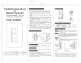
3-Way Wiring Application:
Step 4b
Dimmer Mounting:
TURN OFF POWER AT CIRCUIT BREAKER OR FUSE.
Step 7
Installation may now be
completed by carefully
positioning all wires to
provide room in wall box for
dimmer. Mount dimmer into
box with mounting screws
supplied. Attach wallplate.
• Restore power at circuit breaker or fuse.
• Carefully holding dimmer, move slider
control lever to highest position and move
toggle handle up. Lights should turn ON to
brightest level.
If lights does not turn ON, refer to the
TROUBLESHOOTING section.
Testing your Dimmer prior to mounting in the
wall box:
Step 6
Step 5
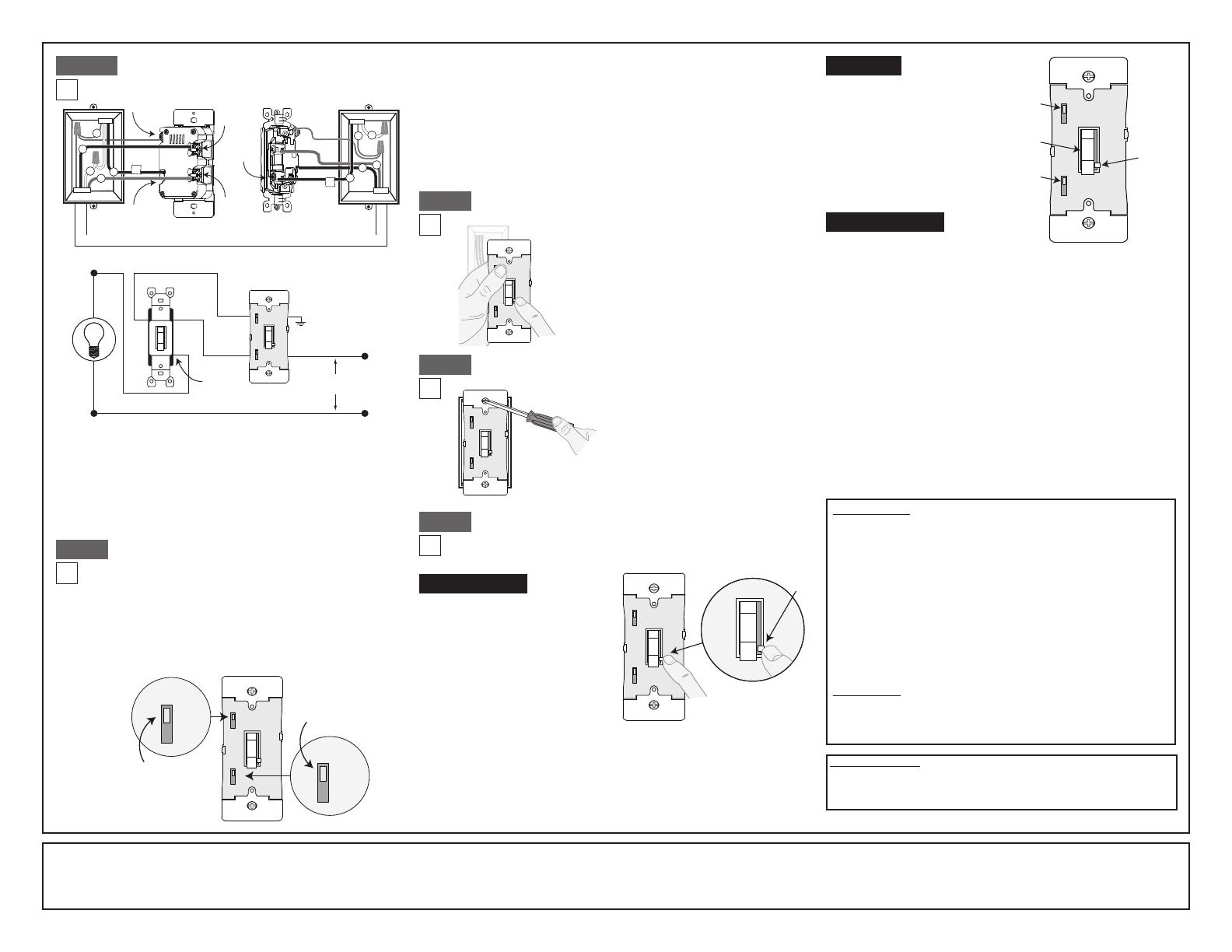
Dimmer Bulb Selector Switch:
Cat. No. TSL06 is pre-set at the factory with the bulb
selector switch set to Mode A (LED/Incandescent).
For CFL bulb applications the switch should be moved
to Mode B (CFL). The lamp selector slide switch also
allows the user to adjust the minimum light level when
dimming. Information on this feature is found under
PROGRAMMING.
NOTE: See illustration for location of bulb selector switch.
Setting Minimum Light Level
1. Move toggle handle down to turn the
dimmer OFF and move the slide bar
to the bottom.
2. Set the bulb selector switch to the
LED/Incandescent position (Mode A).
3. Move toggle handle up to turn the
load ON.
4. Set the bulb selector switch to the
CFL position (Mode B).
5. Raise or lower the slide control level
to achieve the desired minimum light level.
6. Set the bulb selector switch back to LED/Incandescent position (Mode A).
7. A momentary flash of the bulb will occur confirming the new setting.
8. Move toggle handle down to turn the load OFF.
NOTE: For dimmable CFL lamps you must return the bulb selector to the CFL
position (Mode B).
LED/Incandescent (Mode A): The selector switch is pre-set at the factory to this
mode. Use this mode for dimmable LED bulbs and incandescent/halogen bulbs. To
avoid flickering at the low end of the dimming range you can pre-set the minimum
light level. See PROGRAMMING to manually program the minimum light level.
CFL (Mode B): To be used for dimmable CFL bulbs only. In this mode the dimmer
provides a pre-set kick-start to aid the lamp in starting. To avoid flickering at the low
end of the dimming range you can pre-set the minimum light level.
See PROGRAMMING to manually program the minimum light level.
Locator Light Switch (LOC): The LED Locator Light will illuminate when the load is
OFF. To disable the Locator Light move the Locator Light Switch to the OFF position.
DI-000-TSL06-02A
LIMITED 5 YEAR WARRANTY AND EXCLUSIONS
Leviton warrants to the original consumer purchaser and not for the benefit of anyone else that this product at the time of its sale by Leviton is free of defects in materials and workmanship under normal and proper use for five years from the purchase date. Leviton’s only obligation is to correct
such defects by repair or replacement, at its option. For details visit www.leviton.com or call 1-800-824-3005. This warranty excludes and there is disclaimed liability for labor for removal of this product or reinstallation. This warranty is void if this product is installed improperly or in an
improper environment, overloaded, misused, opened, abused, or altered in any manner, or is not used under normal operating conditions or not in accordance with any labels or instructions. There are no other or implied warranties of any kind, including merchantability and fitness for
a particular purpose, but if any implied warranty is required by the applicable jurisdiction, the duration of any such implied warranty, including merchantability and fitness for a particular purpose, is limited to five years. Leviton is not liable for incidental, indirect, special, or consequential
damages, including without limitation, damage to, or loss of use of, any equipment, lost sales or profits or delay or failure to perform this warranty obligation. The remedies provided herein are the exclusive remedies under this warranty, whether based on contract, tort or otherwise.
FOR CANADA ONLY
For warranty information and/or product returns, residents of Canada should
contact Leviton in writing at Leviton Manufacturing of Canada Ltd to the
attention of the Quality Assurance Department, 165 Hymus Blvd, Pointe-
Claire (Quebec), Canada H9R 1E9 or by telephone at 1 800 405-5320.
2
3
4
5
Terminal
Screw Marked
Green (GR)
Terminal
Screw Marked
Red (RD)
Black Screw
(common)
Terminal
Screw Marked
Red (RD)
Dimmer 3-Way
Terminal
Screw Marked
Black (BK)
1
3
1
4
5
2
RD
RD
Black Screw
(common)
3-Way
Green
Ground
BK
Hot (Black)
Neutral (White)
Line
120VAC, 60Hz
Dimmer
Bulb Selector
Switch
Locator Light
Switch
MODE
A
B
OFF
ON
LOC
MODE
A
B
OFF
ON
LOC
• Green or bare copper wall box wire to terminal screw marked "GR".
• Common (Line hot or Load) wire to terminal screw marked "BK".
• Remove insulating label and connect the first traveler wire to the
terminal screw below marked "RD".
• Second traveler wire to the remaining terminal screw marked "RD".
Proceed to Step 5.
Connect wires per WIRING DIAGRAM as follows:
Slide
Bar
MODE
A
B
OFF
ON
LOC
© 2016 Leviton Mfg. Co., Inc
• Lights flickering
- Lamp has bad connection.
- Wires not secured firmly with wire connectors.
• CFL and LED flickers at low end of dimming range
- Increase the low end of the dimming range.
Programming Section - setting minimum light level
• CFL or LED bulb flickers throughout dimming range
- Ensure the bulbs are marked dimmable.
- Please refer to recommended dimmable LED and CFL bulbs at
www.leviton.com/universal.
• Light does not turn ON
- Circuit breaker or fuse has tripped.
- Lamp is burned out.
NOTE: If further information is needed in identifying the HOT wire
in a 3-Way application, go to Leviton's website at www.leviton.com.
ON/OFF:
Move toggle handle up
- Lights will turn ON.
Move toggle handle down
- Lights will turn OFF.
BRIGHTEN & DIM:
Move slide bar
- Lights will BRIGHTEN or DIM.
Troubleshooting
Operation
Programming
FCC STATEMENT
This equipment has been tested and found to comply with the limits for a Class
B digital device, pursuant to part 15 of the FCC Rules. These limits are designed
to provide reasonable protection against harmful interference in a residential
installation. This equipment generates, uses and can radiate radio frequency
energy and, if not installed and used in accordance with the instructions, may
cause harmful interference to radio communications. However, there is no
guarantee that interference will not occur in a particular installation. If this
equipment does cause harmful interference to radio or television reception, which
can be determined by turning the equipment off and on, the user is encouraged
to try to correct the interference by one or more of the following measures:
• Reorient or relocate the receiving antenna.
• Increase the separation between the equipment and receiver.
• Connect the equipment into an outlet on a circuit different from that to which the
receiver is connected.
• Consult the dealer or an experienced radio/TV technician for help.
IC STATEMENT
This device complies with Industry Canada licence-exempt RSS standard(s).
Operation is subject to the following two conditions: (1) this device may not
cause interference, and (2) this device must accept any interference, including
interference that may cause undesired operation of the device.
Toggle
ON/OFF
Bulb
Selector
Switch
Slide Bar
Brighten/
Dim
MODE
A
B
OFF
ON
LOC
Locator
Light
Switch
This product is covered by U.S. Patent No. 8,664,886.