Page is loading ...

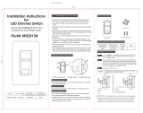
Works with DIMMABLE LED, CFL,
Incandescent and halogen bulbs
Installation Instructions
for Smart
LED Dimmer Switch
● Risk of fire and electrical shock, products should be installed in
accordance with appropriate electrical codes and regulations.
● The product shall be used together with an upstream air-gap switch.
● Turn power off at circuit breaker or fuse and test that power is off before
installing.
●
After installed the dimmer, it is recommended to set the minimum
brightness level to make bulbs turn on immediately and the dimmer
with maximum dimming range.
● If you are unsure about any part of these instructions, consult a
licensed electrician.
● To reduce the risk of overheating and possible damage to other
equipment, do not install to control a receptacle, a motor-operated
appliance or a transformer-supplied appliance.
● Use with compatible dimmable LED, CFL bulbs, Incandescent or
halogen bulbs only.
● When multiple bulbs are used with one dimmer DO NOT mix bulb
types. All bulbs shall be either LED, CFL or incandescent. Using
the same model of each bulb will enhance dimmer performance.
WARNINGS AND CAUTIONS
Model No.
Rated Voltage
Rated Wattage
Load Range
Dimming Mode
Compatible
Loads
Operation
Humidity
Working
Temperature
DNA052M2B-300
120V,60Hz
LED:300W
INCAN.:15W-300W
10% R.H.-90% R.H.
-10~40
1.Dimmable LED lamp
2.Dimmable LED lamp with electronic transformer
3.Incandescent or medium voltage halogen lamp
4.Low voltage halogen lamp with electronic transformer
Phase cut
LED:3W-300W
INCAN.:15W-300W
Functional parts instructions
Brightness adjustment button(Brighten)
On/off switch button
Brightness adjustment button(Dim)
Multi-function indicator
Status indicator
Power switch
Parts information
Wire connectors(5pcs)
dimmer(1pc)
mounting screws(2pcs)
Tools needed to install your Dimmer
Φ5mm Philips Screwdriver Electrical Tape Cuers
Pliers Test Pencil Ruler
Installation and testing
Step 2 Removing existing switch: Remove existing wall plate and
switch mounting screws. Carefully pull switch from wall box,
identify and take out the wires attached to the switch, then
remove the switch. DO NOT remove wires which are taken
out from the switch at this time.(If new configuration is without
this step)
Step 1 WARNING: To avoid fire and electrical shock,TURN
OFF POWER at circuit breaker or fuse and test that
power is off before wiring.
S/N
1
2
3
4
5
6
7
online operation
brightness interval LED indicatorbrightness level
brightness level 1
brightness level 4
brightness level 7
brightness level 10
brightness level 13
brightness level 16
brightness level 19
LED2 brighting
LED2~LED3 brighting
LED2~LED4 brighting
LED2~LED5 brighting
LED2~LED6 brighting
LED2~LED7 brighting
LED2~LED8 brighting
When the
brightness
level is between
two gears, the
current
brightness
indication state
is not changed.
Status indictor
● Indicator lights red : The load light is OFF
● Indicator lights yellow : The load light is ON
Short press: within 0.5s;
Long press: over 0.5s;
Continuous short press: each interval of short press should within 1s.
On/off switch button
● Turn on the light : Short press the button once when the light is off.
● Turn off the light : Short press the button once when the light is on.
● Quick to the Max. brightness: Continuous short press the button twice.
● Set the Min. brightness : Turn on the light and dimming to the Min.
brightness you desire, continuous short press the button 6 times then
finished the Min. brightness setting.
● Recover to the factory default Min. brightness: Continuous short press
the button 9 times when the light is on.
● Switching wire circuit connection way: Continuous short press the
button 8 times, the load light flash twice, switching to Single-Pole/3-
way;the load light flash 3 times, switching to Multi-way.
● Recover to factory default:Continuous short press the button 10 times
when the light is on, the load light flash once(1.Turn on the light will
at Max. brightness;2.the min. brightness at 1%;3.Single-pole/3-Way
circuit connection way.
● Night light: Continuous short press the button 3 times, turn ON/OFF
the night light. Finish the operation:Multi-function indicator flash once
Turn off the night light,Multi-function indicator flash 3 times. Turn on
the night light.
Brightness adjustment button
● Brightness increase: When the light is on, short press the up button
to increase the brightness by one level;
● Brightness decrease: When the light is on, short press the down
button once to decrease the brightness by one level;
● Brightness increases continuously: When the light is on, press and
hold the up button to increase the brightness continuously until it is
released or reaches the maximum brightness.
● Brightness decrease continuously: When the light is on, press and
hold the up button to increase the brightness continuously until it is
released reaches the minimum brightness.
Power switch
● Plug in the power switch to turn on the power;
● Pull out the power switch to turn off the power.
Multi-function indicator
● Function 1: night light;
● Function 2: brightness indicator of load light.
Table of the brightness indication
Installing and fixing the dimmerStep 5
NOTE:
•Dimmer must always be connected to the side with electricity of
the load to ensure normal work.
•Multi-way self-reset switch can control up to 20pcs of dimmer for
UP/DOWN dim and ON/OFF at the same time.
•Two or more dimmers must not be connected in parallel or series
to control the same load from two different locations.
One self-reset switch control Multiple dimmer wiring diagram
Step 4c-2
NOTE:
•One self-reset switch can control up to 20pcs of dimmer for
UP/DOWN dim and ON/OFF at the same time.
Multiple self-reset switches control multi-way dimmers wiring
diagram
Step 4c-3
NOTE:
•Multi-way self-reset switch can control up to 20pcs of dimmer for
UP/DOWN dim and ON/OFF at the same time.
Black
White
Yellow and
Green
Red
Grey
Load
Ground
Neutral
Hot
signal wire
● Connect the yellow and green dimmer wire to the green or bare
copper ground wire in the wall-box, and twist them with wire nut.
● Connect the black dimmer wire to the hot input wire with tag removed
from the switch, and twist them with wire nut.
● Connect the white dimmer wire to the neutral wire,and twist them with
wire connector.
● Connect the red dimmer wire, gray dimmer wire to the remaining
3-way switch’s two wires removed from the switch, and twist them
with wire nuts.
(Note: The red wire on the dimmer is connected to the load wire on
the 3-way Switch.)
● Carefully position all wires inside the wall-box, leaving enough room
to insert the dimmer housing. Put the dimmer inside the wall-box.
● Mount the dimmer securely inside the wall-box using the provided
mounting screws.
wall-box
mounting screws
Step 3 ldentifying the type of circuit
If the wiring in the wall box does not resemble any of these
configurations, consult an electrician.
NOTE:
IMPORTANT: For 3-Way applications, note that one of the screw
terminals from the old switch being removed will usually be a
different color (Black) or labeled Common. Tag that wire with electrical
tape and identify as the common (Line or Load) in both the dimmer
wall box and 3-way wall box.
Single-Pole 3-Way
Li ne (Hot)
N eutral
G round
Lo ad
Li ne or Load
(See note below)
N eutral
G round
F irst Traveler note color
S econd Traveler note color
Step 4a Single-Pole Wiring Application
Dimmer
Black
Hot(Black)
Red
White
Yellow and
Green Ground
Line 120VAC, 60Hz
Neutral(White)
Grey
This wire is used in 3-way
installations only.
For single pole installations,
twist with wire nut
Load
Neutral
Red
Yellow and
Green
Black
White
Grey
Ground
Neutral
Hot
●Connect the yellow and green dimmer wire to the green or bare copper
ground wire in the wall-box, and twist them with wire connector.
●Connect the black dimmer wire to the hot input wire removed from the
switch, and twist them with wire connector.
●Connect the white dimmer wire to the neutral wire,and twist them with
wire connector.
●Connect the red dimmer wire to the load wire removed from the switch,
and twist them with wire connector.
●Use remaining wire connector to cap the remaining grey wire of the
dimmer.
Step 4b 3-Way Wiring Application:
Dimmer
Black
Hot(Black)
Red
White
Yellow and
Green Ground
Line 120VAC, 60Hz
Neutral(White)
Grey
Yellow and
Green Ground
3-Way Switch
Common Terminal
(Black Screw)
Load
Neutral
Red
Yellow and
Green
Black
White
Grey
Ground
Neutral
Hot
signal wire
IMPORTANT: In a 3-way circuit, only one dimmer can be used.
● Connect the yellow and green dimmer wire to the green or bare
copper ground wire in the wall-box, and twist them with wire nut.
● Connect the black dimmer wire to the hot input wire with tag removed
from the switch, and twist them with wire nut.
● Connect the white dimmer wire to the neutral wire,and twist them with
wire connector.
● Connect the red dimmer wire, gray dimmer wire to the remaining
3-way switch’s two wires removed from the switch, and twist them
with wire nuts.
(Note: The red wire on the dimmer is connected to the load wire on
the 3-way Switch.)
Step 4c Multi-Way Wiring Application:
Switching wire circuit connection way: Continuous short press the button
8 times
Multiple self-reset switches control one dimmer wiring diagram
Step 4c-1
Step 4 Typical wiring connection way
Installing wall plate
Step 6
Separated plate
Step 6a
● Place the mounting frame over your installed dimmer and secure
it using provided screws.
● Cover the face plate over the installed mounting frame and gently
push it to ensure flush fit.
Mounting Frame
Integrated plateStep 6b
● Place the plate over your installed dimmer and secure it using
provided screws.
Troubleshooting
Provided screws
Mounting Frame
Face Plate
Provided screws
Plate
Using Description
Function Description
Wiring method
Single-pole
Table of the function in Single-pole wiring
Dimmer
operation
√
√
√
√
√
√
√
Function
Turn on/off the light
Dimming
Quick to the Max. brightness
Set the Min. brightness
Reset the default brightness
Reset to the factory default
Switching wiring method
Opreation of On/off switch
● Turn on the light: Press to turn on the light when it is off;
● Turn off the light: Press to turn off the light when it is on;
Opreation of self-reset switch
● Turn on the light: Press once to turn on the light when it is off;
● Turn off the light: Press once to turn off the light when it is on;
● Dimming: Press and hold to adjust the brightness of the light, press
and hold again to change the direction of the brightness after released.
● Quick to the maxinum brightness: Press the switch twice to dimming
the light to the maximum brightness.
Problem Possible Cause Soluon
Lights flickering
Lamp has a bad connecon Reconnect and fix the wires
LED and CFL flickers at low
end of dimming range Load compability is not good Turn up lamp minimum
brightness properly
Light does not turn on
Circuit breaker has tripped Turn power on
Fuse burn out Change fuse
Lamp burned out Change lamp
Lamp neutral connecon
is not wired Reconnect the lamp neutral
One dimmer connect to mulple
types bulb, incur interference
and cause flicker
Change bulbs to same type
The wiring of the other switch is
incorrect when using in a 3-way
circuit
Reconnect the circuit
Wiring
method
3-Way
Table of the function in 3-Way wiring
Function
Turn on/off the light
Dimming
Quick to the Max. brightness
Set the Min. brightness
Reset the default brightness
Reset to the factory default
Switching wiring method
Dimmer
operation
√
√
√
√
√
√
√
On/off switch
operation
√
×
×
×
×
×
×
Group control ×√
Table of the function in Multi-Way wiring
Wiring
method
Multi
-Way
Function
Turn on/off the light
Dimming
Quick to the Max. brightness
Set the Min. brightness
Reset the default brightness
Reset to the factory default
Switching wiring method
Dimmer
operation
√
√
√
√
√
√
√
Self-reset
switch
operation
√
×
×
×
×
×
×
Group control ×√
Part#: M520140
/