Page is loading ...

Toll Free 800.988.8103
Tel 360.650.1111
Fax 360.650.1166
www.woodstone-corp.com
WOOD STONE CORPORATION
1801 W. Bakerview Rd.
Bellingham, WA 98226 USA
FIRE DECK SERIES
Stone Hearth Oven
Gas-Fired, Gas/Wood Combination Models
FIRE DECK 8645 WS-FD-8645
DOC NO M0039.12 REVISED DECEMBER 2019
Installation and
Operation Manual

TABLE OF CONTENTS
Fire Deck 8645 � � � � � � � � � � � � � � � � � � 3
Cautions & Warnings � � � � � � � � � � � � � � 4
FD-8645 Specifications � � � � � � � � � � � � � 6
Unloading & Moving the Oven � � � � � � � � � 7
Optional Temp Caster Install � � � � � � � � � � 8
Placing & Installation � � � � � � � � � � � � � � 9
Installation Clearances � � � � � � � � � � � � 10
Facade Guidelines � � � � � � � � � � � � � � � 11
Facade Requirements � � � � � � � � � � � � � 12
Venting � � � � � � � � � � � � � � � � � � � � � � 13
Gas Specifications � � � � � � � � � � � � � � � 15
Electrical Specifications � � � � � � � � � � � � 17
Controller � � � � � � � � � � � � � � � � � � � � 18
Oven Start-Up � � � � � � � � � � � � � � � � � � 19
Daily Oven Operation � � � � � � � � � � � � � 20
Flame Height Control � � � � � � � � � � � � � 21
Use of Wood in the Oven � � � � � � � � � � � 22
Daily Maintenance & Cleaning � � � � � � � � 23
Troubleshooting Guide� � � � � � � � � � � � � 24
Fuelwood Facts � � � � � � � � � � � � � � � � � 25
Decorative Flame Burner � � � � � � � � � � � 26
Electrical Diagrams � � � � � � � � � � � � � � 27
Interlock Diagram � � � � � � � � � � � � � � � 30
Limited Warranty � � � � � � � � � � � � � � � � 31
Fire Deck 8645
Installation and Operation Manual
PG 2 OF 32
M0039.12 DECEMBER 2019
An ongoing program of product improvement may
require us to change specifications without notice.
WOOD STONE CORPORATION
1801 W. Bakerview Rd.
Bellingham, WA 98226 USA
TOLL FREE 800.988.8103
TEL 360.650.1111
FAX 360.650.1166
E-MAIL info@woodstone-corp.com
woodstone-corp.com
TABLE OF CONTENTS

Fire Deck 8645
Installation and Operation Manual
PG 3 OF 32
M0039.12 DECEMBER 2019
An ongoing program of product improvement may
require us to change specifications without notice.
WOOD STONE CORPORATION
1801 W. Bakerview Rd.
Bellingham, WA 98226 USA
TOLL FREE 800.988.8103
TEL 360.650.1111
FAX 360.650.1166
E-MAIL info@woodstone-corp.com
woodstone-corp.com
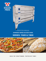
FIRE DECK 8645
INSTALLATION AND OPERATION MANUAL FOR THE
WOOD STONE FIRE DECK
STONE HEARTH COOKING EQUIPMENT
WS-FD-8645-(RFG)-(LR, L, R)-(IR)-(W)-(NG, LP) MODELS
GAS-FIRED / WOOD-FIRED & COMBINATION MODELS
ADDITIONAL COPIES AVAILABLE UPON REQUEST
Shown: FD-8645-L/R with
optional Decorative Flame

Fire Deck 8645
Installation and Operation Manual
PG 4 OF 32
M0039.12 DECEMBER 2019
An ongoing program of product improvement may
require us to change specifications without notice.
WOOD STONE CORPORATION
1801 W. Bakerview Rd.
Bellingham, WA 98226 USA
TOLL FREE 800.988.8103
TEL 360.650.1111
FAX 360.650.1166
E-MAIL info@woodstone-corp.com
woodstone-corp.com
CAUTIONS & WARNINGS
WOOD STONE WS-FD-8645 FIRE DECK INSTALLATION AND OPERATING INSTRUCTIONS
IMPORTANT: Consult your local gas supplier for a statement outlining a procedure to be followed
in the event you smell gas. Post the statement in a prominent location.
CAUTION: Disconnect power to the oven before servicing or cleaning.
No attempt should be made to operate this appliance during a power failure.
RETAIN THIS MANUAL FOR FUTURE REFERENCE
Additional copies of this manual at woodstone-corp�com�
For prompt responses to service/maintenance questions, call us at @ 1-800-988-8103�
FOR YOUR SAFETY: Do not store or use gasoline or other flammable vapors or liquids in the vicinity of
this or any other appliance.
ESURE DE SÉCURITÉ: Ne pas entreposer ni utiliser de’essence ni autres vapeurs ou liquides
inflammables à proximté de cet appareil ou de tout autre appareil.
WARNING: Improper installation, adjustment, alteration, service or maintenance can cause property
damage, injury or death. Read the installation, operation and maintenance instructions thoroughly before
installing or servicing this equipment.
AVERTISSEMENT: L’installation, le réglage, la modification, la réparation ou l’entretien incorrect de
cet appareil peut causer des dommages matériels, des blessures ou la mort. Lire attentivement les
instructions d’installation, de fonctionnement et d’entretien avant de procéder à son installation ou
entretien.
Always keep the area under and around this appliance free and clear of any and all combustible materials.
READ ALL INSTRUCTIONS BEFORE INSTALLING AND USING THIS APPLIANCE
Please read this entire manual before you install the oven. Failure to follow instructions may result in
property damage, bodily injury or even death. Contact your local building or fire officials about restrictions
and installation inspection in your area.

Fire Deck 8645
Installation and Operation Manual
PG 5 OF 32
M0039.12 DECEMBER 2019
An ongoing program of product improvement may
require us to change specifications without notice.
WOOD STONE CORPORATION
1801 W. Bakerview Rd.
Bellingham, WA 98226 USA
TOLL FREE 800.988.8103
TEL 360.650.1111
FAX 360.650.1166
E-MAIL info@woodstone-corp.com
woodstone-corp.com
CAUTIONS & WARNINGS
Wood Stone ovens
have been tested and approved by Intertek Testing Services and
conform to ANSI Z83.11, UL 2162, UL 737 and CGA 2.17;
are certified to CSA 1.8, ULC/ORD 2162 and ULC S627;
and to NSF/ANSI 4.
SAVE THE INSTRUCTIONS
This product must be installed by a licensed plumber or gas fitter when installed within the Commonwealth
of Massachusetts.
It is recommended that this oven be installed, maintained and
serviced by authorized professionals.
A MAJOR CAUSE OF OVEN RELATED FIRES IS A
FAILURE TO MAINTAIN REQUIRED CLEARANCES
TO COMBUSTIBLE MATERIAL. IT IS OF UTMOST
IMPORTANCE THAT THIS OVEN BE INSTALLED ONLY
IN ACCORDANCE WITH THESE INSTRUCTIONS.
ANSI Z83.11:2016 Ed.4
CSA 1.8:2016 Ed.4
ANSI/NSF 4:2016

Fire Deck 8645
Installation and Operation Manual
PG 6 OF 32
M0039.12 DECEMBER 2019
An ongoing program of product improvement may
require us to change specifications without notice.
WOOD STONE CORPORATION
1801 W. Bakerview Rd.
Bellingham, WA 98226 USA
TOLL FREE 800.988.8103
TEL 360.650.1111
FAX 360.650.1166
E-MAIL info@woodstone-corp.com
woodstone-corp.com
FD-8645 SPECIFICATIONS
Electrical
120 VAC, 1�1 A, 50/60 Hz
240 VAC, 1 A, 60 Hz (optional)
Utility connection made on the left
side of oven as shown�
Refer to data plate when installing�
UTILITIES SPECIFICATIONS
Gas
3/4 inch gas inlet (FNPT)
225,000 BTU/hr Natural Gas (NG)
OR
200,000 BTU/hr Propane (LP)
Optional Decorative Flame adds
15,000 BTU/hr to total rated input
Maximum gas inlet pressure:
1/2 psi (14 inches W�C�)
Shipping weight: 4,350 lbs.
Air intake: Do not
facade or cover over
Must be left
removable for service
Venting
The Fire Deck 8645 must be vented using a Listed Type
1 exhaust hood, or a hood constructed and installed
in accordance with NFPA 96 and all relevant local and
national codes� The oven must be vented in accordance
with all relevant local and national codes, and in a manner
acceptable to the authority having jurisdiction�
Important: Models with -W in the model number must be
vented as a solid fuel appliance�
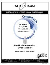
Exhaust
Plan view
Front view
REV:
LEGEND:
PART #:
FD-8645-RFG-L/R-IR
8645 Fire Deck
General Arrangement
5/10/2018
lucasm
3
DWN BY:
SHEET:
Bellingham, WA 360/650-1111 www.woodstone-corp.com
DIMENSIONS ARE IN INCHES
TOLERANCES: LINEAR ±1/2 [±10mm], ANGULAR ±2°
UNLESS NOTED OTHERWISE
\\woodstone\dfs\CAD\0 Pn\WS Top Level\FD-Fire_Deck\FD-8645_General_Arrangement-3.dft
THE INFORMATION CONTAINED IN THIS DRAWING IS THE
SOLE PROPERTY OF WOOD STONE CORPORATION
ANY REPRODUCTION OR USE IN PART OR AS A WHOLE
WITHOUT THE WRITTEN PERMISSION OF WOOD STONE IS
PROHIBITED
AN ONGOING PROGRAM OF PRODUCT IMPROVEMENT
MAY REQUIRE US TO CHANGE SPECIFICATIONS
WITHOUT NOTICE.
DATE:
G
120VAC, 1.1A, 50/60 Hz
GAS INLET: 3/4" NPT
225,000 BTU, NG (RFG-L/R-IR)
200,000 BTU, LP
(RFG-L/R-IR)
1 of 1
AIR INTAKE
G
G
33 3/4"
860mm
40 1/2"
1030mm
48"
1220mm
29 3/4"
760mm
3"
80mm
17"
430mm
9 3/4"
250mm
3 1/4"
80mm
43"
1090mm
R
12"
300mm
Cleaning Position
Swing Radius
85 3/4"
2180mm
45"
1150mm
5"
130mm
59 3/4"
1520mm
7 1/2"
190mm
52 1/2"
1330mm
6"
150mm
1"
30mm
13 1/4"
340mm
17 3/4"
450mm
2"
50mm
55 3/4"
1420mm
74 1/4"
1890mm
9 3/4"
250mm
14"
360mm
23 3/4"
600mm
24 3/4"
630mm
25 1/2"
650mm
77 1/2"
1970mm
10 1/4"
260mm
4"
100mm
10"
250mm
Side view
REV:
LEGEND:
PART #:
FD-8645-RFG-L/R-IR
8645 Fire Deck
General Arrangement
5/10/2018
lucasm
3
DWN BY:
SHEET:
Bellingham, WA 360/650-1111 www.woodstone-corp.com
DIMENSIONS ARE IN INCHES
TOLERANCES: LINEAR ±1/2 [±10mm], ANGULAR ±2°
UNLESS NOTED OTHERWISE
\\woodstone\dfs\CAD\0 Pn\WS Top Level\FD-Fire_Deck\FD-8645_General_Arrangement-3.dft
THE INFORMATION CONTAINED IN THIS DRAWING IS THE
SOLE PROPERTY OF WOOD STONE CORPORATION
ANY REPRODUCTION OR USE IN PART OR AS A WHOLE
WITHOUT THE WRITTEN PERMISSION OF WOOD STONE IS
PROHIBITED
AN ONGOING PROGRAM OF PRODUCT IMPROVEMENT
MAY REQUIRE US TO CHANGE SPECIFICATIONS
WITHOUT NOTICE.
DATE:
G
120VAC, 1.1A, 50/60 Hz
GAS INLET: 3/4" NPT
225,000 BTU, NG (RFG-L/R-IR)
200,000 BTU, LP
(RFG-L/R-IR)
1 of 1
AIR INTAKE
G
G
33 3/4"
860mm
40 1/2"
1030mm
48"
1220mm
29 3/4"
760mm
3"
80mm
17"
430mm
9 3/4"
250mm
3 1/4"
80mm
43"
1090mm
R
12"
300mm
Cleaning Position
Swing Radius
85 3/4"
2180mm
45"
1150mm
5"
130mm
59 3/4"
1520mm
7 1/2"
190mm
52 1/2"
1330mm
6"
150mm
1"
30mm
13 1/4"
340mm
17 3/4"
450mm
2"
50mm
55 3/4"
1420mm
74 1/4"
1890mm
9 3/4"
250mm
14"
360mm
23 3/4"
600mm
24 3/4"
630mm
25 1/2"
650mm
77 1/2"
1970mm
10 1/4"
260mm
4"
100mm
10"
250mm
NOTES
This oven is available in a left, right or left and right side
burner configurations� The utility connections will always
be on the left side�
NOTE: The casters will add 3" to the height of the oven,
for a total height of 81-1/4"� The 3-3/4" vent shield on
top can be removed temporarily if necessary�

Fire Deck 8645
Installation and Operation Manual
PG 7 OF 32
M0039.12 DECEMBER 2019
An ongoing program of product improvement may
require us to change specifications without notice.
WOOD STONE CORPORATION
1801 W. Bakerview Rd.
Bellingham, WA 98226 USA
TOLL FREE 800.988.8103
TEL 360.650.1111
FAX 360.650.1166
E-MAIL info@woodstone-corp.com
woodstone-corp.com
UNLOADING & MOVING THE OVEN
CAUTION HOT PRUDENCE CHAUD
USING A FORKLIFT.
The Wood Stone Fire Deck 8645 weighs approximately 4,350 lbs� and is top-heavy�
Use a forklift with adequate fork lengths and lifting capacity� When using a forklift, always use the forklift pockets� Lifting the oven
any other way with a forklift may result in damage� Use extreme caution and make sure that the forks extend all the way through the
pockets provided� Fork length must be at least 6' long� If it is necessary to approach the oven from the front, be sure the mast does
not contact the mantle (shelf)�
There are fork pockets at the front and sides of the oven� Note: Forklift capacity is different if lifting from the front/rear or the sides�
Once the oven is on a smooth, flat, level floor it can be rolled on its optional heavy-duty, temporary shipping Casters (details next
page)�
USING A PALLET JACK.
The oven may also be moved with a Pallet Jack using the front or rear fork pockets only� Once the oven is on a smooth, flat, level
floor it can be rolled to its final position� DO NOT ATTEMPT TO MANUALLY ROLL THE OVEN UP OR DOWN A RAMP OR INCLINE.
Do not position yourself between the moving oven and an immovable object or surface such as a wall or door frame�
DO NOT TURN THE OVEN ON ITS SIDE!.
Moving a Wood Stone oven can present interesting challenges to even the most
experienced riggers� Make sure to secure the proper equipment and make safety
your first priority� Please don’t hesitate to call the factory for technical support�
USING A CRANE.
If you are planning to use a crane to unload the oven,
specify a flatbed truck delivery.
Use the pickeyes provided on the sides of the oven to lift the
oven with a crane� The spreader bar should be of a sufficient
length to keep the sling from contacting the oven, and oriented
as shown in fig� 1�
DELIVERY NOTE.
The customer will receive an Oven Shipping Notification when
the oven leaves the Wood Stone factory� This will include a
PRO# and a trucking company contact number� Wood Stone
recommends that you confirm the delivery date/time with the
trucking company before committing to heavy equipment and/
or labor� Our goal is a smooth and safe delivery�
Pickeye Capacity
per Beam
4,000 lbs
LOAD
Orient Spreader Bar
as shown in fig. 1
50°MIN Angle
fig. 1
Pickeye
Beam
Front Forklift / Pallet Jack Pockets Side Forklift Pockets
Minimum Required
Forklift Capacities
6' FORKS MINIMUM
Model
Lifting from
Front or Rear
Lifting from
Sides
FD-8645 8,000 lbs 9,000 lbs
WARNING
Use caution
near mantle

Fire Deck 8645
Installation and Operation Manual
PG 8 OF 32
M0039.12 DECEMBER 2019
OPTIONAL TEMP CASTER INSTALL
INSTRUCTIONS FOR INSTALLING AND REMOVING OPTIONAL OVEN CASTERS
The Fire Deck 8645 weighs 4,350 lbs.
Do not attempt to move the oven over any type of grade or sloped surface when using the Casters or Pallet Jack.
WARNING: Failure to follow these instructions may result in severe injury or death. BE SAFE.
If you have any questions call Wood Stone at 800.988.8103.
NOTE: The casters will add 3" to the total height of the oven, for a total of 80-1/4".
The 3-3/4" Vent Shield on top can be removed temporarily if necessary.
Shipping Casters are for moving the oven only. THEY MUST BE REMOVED ONCE THE OVEN IS IN PLACE.
1 Use a forklift (or pallet jack) to raise the oven
using the front or rear forklift pockets�
3 Once at final destination, use two scissor jacks (or
pallet jack) to lift the one side of the oven by placing
one jack under each caster assembly�
Raise the oven just high enough so the wheels clear
the floor�
Unbolt each Caster and remove it�
Note: Casters are for moving oven only� They must
be removed once the oven is in place�
4 Lower the oven back to the ground�
Remove the Self-Drilling Screw and slide the rest of
the Caster Assembly out of the fork pocket�
Install Fork Pocket Covers�
Repeat steps 3 and 4 for the other side of the oven�
This oven is designed to be sealed to the floor upon
installation using a silicone sealant acceptable to the
local health official� See the Placing & Installation
section of this manual for additional information�
Caster Bolts
2 Insert a Caster Assembly into each of the side
fork pockets and secure it to the oven with a
Self-Drilling Screw and washer�
Install the screw through the Mounting Tab�
Once the Caster Assemblies are installed, lower
the oven�
It may then be rolled over a smooth flat
surface to its final destination�
Self-Drilling Screw
& Washer through
Mounting Tab

Fire Deck 8645
Installation and Operation Manual
PG 9 OF 32
M0039.12 DECEMBER 2019
PLACING & INSTALLATION
L1217
ATTENTION INSTALLER
Fork Pocket Cover
MUST be installed
over pocket for oven
to operate properly.
L1217
ATTENTION INSTALLER
Fork Pocket Cover
MUST be installed
over pocket for oven
to operate properly.
L1217
ATTENTION INSTALLER
Fork Pocket Cover
MUST be installed
over pocket for oven
to operate properly.
L1217
ATTENTION INSTALLER
Fork Pocket Cover
MUST be installed
over pocket for oven
to operate properly.
L1217
ATTENTION INSTALLER
Fork Pocket Cover
MUST be installed
over pocket for oven
to operate properly.
L1217
ATTENTION INSTALLER
Fork Pocket Cover
MUST be installed
over pocket for oven
to operate properly.
L1217
ATTENTION INSTALLER
Fork Pocket Cover
MUST be installed
over pocket for oven
to operate properly.
L1217
ATTENTION INSTALLER
Fork Pocket Cover
MUST be installed
over pocket for oven
to operate properly.
REAR FORK POCKETS
Pocket covers
arrive
fastened in
temporary UP
position.
Unfasten, lower
over each fork
pocket, and
refasten.
L1217
ATTENTION INSTALLER
Fork Pocket Cover
MUST be installed
over pocket for oven
to operate properly.
L1217
ATTENTION INSTALLER
Fork Pocket Cover
MUST be installed
over pocket for oven
to operate properly.
L1217
ATTENTION INSTALLER
Fork Pocket Cover
MUST be installed
over pocket for oven
to operate properly.
L1217
ATTENTION INSTALLER
Fork Pocket Cover
MUST be installed
over pocket for oven
to operate properly.
L1217
ATTENTION INSTALLER
Fork Pocket Cover
MUST be installed
over pocket for oven
to operate properly.
L1217
ATTENTION INSTALLER
Fork Pocket Cover
MUST be installed
over pocket for oven
to operate properly.
L1217
ATTENTION INSTALLER
Fork Pocket Cover
MUST be installed
over pocket for oven
to operate properly.
L1217
ATTENTION INSTALLER
Fork Pocket Cover
MUST be installed
over pocket for oven
to operate properly.
L1217
ATTENTION INSTALLER
Fork Pocket Cover
MUST be installed
over pocket for oven
to operate properly.
L1217
ATTENTION INSTALLER
Fork Pocket Cover
MUST be installed
over pocket for oven
to operate properly.
L1217
ATTENTION INSTALLER
Fork Pocket Cover
MUST be installed
over pocket for oven
to operate properly.
L1217
ATTENTION INSTALLER
Fork Pocket Cover
MUST be installed
over pocket for oven
to operate properly.
L1217
ATTENTION INSTALLER
Fork Pocket Cover
MUST be installed
over pocket for oven
to operate properly.
L1217
ATTENTION INSTALLER
Fork Pocket Cover
MUST be installed
over pocket for oven
to operate properly.
L1217
ATTENTION INSTALLER
Fork Pocket Cover
MUST be installed
over pocket for oven
to operate properly.
L1217
ATTENTION INSTALLER
Fork Pocket Cover
MUST be installed
over pocket for oven
to operate properly.
GAS INLET SIDE FORK POCKETS
Unfasten,
place one cover
over each fork
pocket, and
refasten.
Two pocket covers
will arrive fastened in
temporary UP
position above front-
most fork pocket.
L1217
ATTENTION INSTALLER
Fork Pocket Cover
MUST be installed
over pocket for oven
to operate properly.
L1217
ATTENTION INSTALLER
Fork Pocket Cover
MUST be installed
over pocket for oven
to operate properly.
L1217
ATTENTION INSTALLER
Fork Pocket Cover
MUST be installed
over pocket for oven
to operate properly.
L1217
ATTENTION INSTALLER
Fork Pocket Cover
MUST be installed
over pocket for oven
to operate properly.
L1217
ATTENTION INSTALLER
Fork Pocket Cover
MUST be installed
over pocket for oven
to operate properly.
L1217
ATTENTION INSTALLER
Fork Pocket Cover
MUST be installed
over pocket for oven
to operate properly.
L1217
ATTENTION INSTALLER
Fork Pocket Cover
MUST be installed
over pocket for oven
to operate properly.
L1217
ATTENTION INSTALLER
Fork Pocket Cover
MUST be installed
over pocket for oven
to operate properly.
NON-GAS INLET SIDE FORK POCKETS
Pocket covers
arrive
fastened in
temporary UP
position.
Unfasten, lower
over each fork
pocket, and
refasten.
Note: Additional
Tek screws
supplied in
hardware kit.
• • • •
••
••
ÜÜ
• •• •
ÜÜ
ÜÜ
• • • •
••
••
ÜÜ
FORK POCKET
COVER
INSTALLATION
Fork pocket covers
(Both sides & rear)
Fork pocket covers
(Both sides & rear)
Stainless Steel Toe Kick
PLACING THE OVEN
The oven must be installed on a flat level surface� The weight of the oven is carried by the full perimeter of the oven stand� If it is
necessary to shim the oven for leveling purposes, it is critical that the shim material be metal, and that the shims are installed in such
a way that the full perimeter of the stand is solidly supported� Any gaps created by shimming between the oven and the floor must be
sealed (using a silicone sealant acceptable to the local health official) to prevent airflow issues beneath the oven� Failure to solidly
support the full perimeter of the oven stand can result in costly damage to the oven and will void the warranty.
The floor design and construction must be adequate to handle the weight of the oven�
See woodstone-corp.com for floor loading information�
TOE KICK AND FORK POCKET COVERS
Once the oven is in place, the Toe Kick must be installed along the front, and the Fork Pockets on the sides and back of the oven using
the screws provided� The area under the oven must be enclosed in order to prevent pests from entering this space and to prevent air
flow issues which can detrimentally effect burner operation�
FACADE READY OVENS: If the lower front of the oven is shipped facade ready, the toe kick will not be included� Instead, fork pocket
covers and pre-cut blocks of cement board to cover the pocket covers will be included�
If the sides and/or rear of the oven is shipped facade ready, the Fork Pocket Covers will not be included� Pre-cut blocks of cement
board or other facade material will be shipped instead of the Fork Pocket Covers� The blocks must be inserted into the fork pockets
before the oven facade is put in place�

Fire Deck 8645
Installation and Operation Manual
PG 10 OF 32
M0039.12 DECEMBER 2019
An ongoing program of product improvement may
require us to change specifications without notice.
WOOD STONE CORPORATION
1801 W. Bakerview Rd.
Bellingham, WA 98226 USA
TOLL FREE 800.988.8103
TEL 360.650.1111
FAX 360.650.1166
E-MAIL info@woodstone-corp.com
woodstone-corp.com
INSTALLATION CLEARANCES
TO REDUCE THE RISK OF FIRE, FOLLOW THESE INSTALLATION INSTRUCTIONS. A MAJOR CAUSE OF OVEN RELATED FIRES IS
FAILURE TO MAINTAIN REQUIRED CLEARANCES (AIR SPACES) TO COMBUSTIBLE MATERIALS. IT IS OF UTMOST IMPORTANCE
THAT THIS OVEN BE INSTALLED ONLY IN ACCORDANCE WITH THESE INSTRUCTIONS.
1. The Wood Stone Fire Deck oven must have a minimum 1-inch clearance to combustibles from all sides, and 24-inch
clearance to combustibles from the top� If building materials will contact the oven, they must be completely non-combustible�
Please note that standard Drywall (or Sheetrock) is considered a combustible� When non-combustible building materials
contact the body of the oven, the respective clearances are transferred to those non-combustibles�
2. Any facade 6 inches to either side of the oven doorway or above, must be constructed of non-combustible building materials�
3. For gas-only models, this oven is suitable for installation on combustible floors (convient à l’installation sur un plancher
combustible)�
For gas/wood combination models, this oven is suitable for installation on combustible floors (convient à l’installation
sur un plancher combustible)� The minimum hearth extension area to be covered with a non-combustible floor surface must
extend 36 inches in front of and 30 inches to either side of the oven door opening�
!
WARNING: Installation and servicing of this product could expose you to glasswool/ceramic fibers as well
as calcium silicate dust� ALWAYS WEAR RESPIRATORY AND EYE PROTECTION WHEN INSTALLING OR
SERVICING THIS APPLIANCE. Please read this entire manual before you install the oven� Failure to follow
instructions may result in property damage, bodily injury or even death� Contact your local building or fire
officials about restrictions and installation inspection in your area�
!
WARNING: Do not pack required air spaces (clearance) with insulation or other material� When
non-combustible building materials contact the body of the oven, the clearances to combustibles are
transferred to those non-combustibles�
Maintain 24-inch
clearance from
the top
1-inch minimum
side clearance
to combustible
construction
CAUTION HOT PRUDENCE CHAUD
Gas-only models:
Suitable for
installation on
combustible
floors
Gas/wood combination models: This oven is suitable for installation on combustible floors (convient à l’installation
sur un plancher combustible)� The minimum hearth extension area to be covered with a non-combustible floor
surface must extend 36 inches in front of and 30 inches to either side of the oven door opening�

Fire Deck 8645
Installation and Operation Manual
PG 11 OF 32
M0039.12 DECEMBER 2019
An ongoing program of product improvement may
require us to change specifications without notice.
WOOD STONE CORPORATION
1801 W. Bakerview Rd.
Bellingham, WA 98226 USA
TOLL FREE 800.988.8103
TEL 360.650.1111
FAX 360.650.1166
E-MAIL info@woodstone-corp.com
woodstone-corp.com
FACADE GUIDELINES
If planning a decorative facade for the front of the oven, please refer to the diagram below.
Any facade materials that contact the oven must be noncombustible.
Failure to follow the instructions above may void the oven warranty
Flame Height Control Knobs
DO NOT BLOCK
Door Towers
DO NOT COVER
These must remain
removable to allow
for service of the
door (heat shield)
mechanism.
Service Access Panel / Storage Box - DO NOT BLOCK
Provides the only access for service to the gas and electrical components�
Air Intake
DO NOT BLOCK
Oven Controller
Make sure any covering
installed on the oven does
not interfere with the hinges
on the control box.
Total thickness of facade materials, including
the cement board, must not exceed 1-inch in
area above door to allow removal of door system
components for service.
ABOUT FACADE MATERIALS
Fire Deck Series ovens can be finished with any non-combustible decorative material that can be easily affixed to the oven
surface, including tile, stone or brick� It is always advisable to consult with the appropriate authority having jurisdiction before
proceeding as there may be regulations regarding the suitability of various materials� Temperatures above the oven doorway can
reach over 200 °F� Select materials and adhesives suitable for that temperature�
Oven Arches
DO NOT REMOVE
Removal will affect
structural integrity,
heat retention, operation
and void the Warranty�
CAUTION HOT PRUDENCE CHAUD

INSTALLATION
Fire Deck 8645
Installation and Operation Manual
PG 12 OF 32
M0039.12 DECEMBER 2019
An ongoing program of product improvement may
require us to change specifications without notice.
WOOD STONE CORPORATION
1801 W. Bakerview Rd.
Bellingham, WA 98226 USA
TOLL FREE 800.988.8103
TEL 360.650.1111
FAX 360.650.1166
E-MAIL info@woodstone-corp.com
woodstone-corp.com
FACADE REQUIREMENTS
The Facade Ready Fire Deck features cement board already installed on the front surfaces of the oven� ANY MATERIALS AFFIXED
TO THE CEMENT BOARD MUST BE NONCOMBUSTIBLE.
The hatched area represents
surfaces of the oven that are
covered with cement board
at the factory� All parts of the
oven which are meant to be left
exposed are not hatched (see
previous page)�
A 1-inch wide stainless steel lip
is provided, around the doorway
opening and around the air
intake vent� This is provided
so that the noncombustible,
sanitation approved materials
used to cover the cement board
can be neatly terminated at
these points�
Total thickness of facade
materials, including the cement
board, should not exceed
1-inch in thickness in area
above the door to allow removal
of door system components for
service�
OVEN
CEMENT BOARD
1-inch stainless steel
perimeter lip
Tile or other noncombustible,
sanitation approved material
(supplied by others).
CAUTION HOT PRUDENCE CHAUD

Fire Deck 8645
Installation and Operation Manual
PG 13 OF 32
M0039.12 DECEMBER 2019
An ongoing program of product improvement may
require us to change specifications without notice.
WOOD STONE CORPORATION
1801 W. Bakerview Rd.
Bellingham, WA 98226 USA
TOLL FREE 800.988.8103
TEL 360.650.1111
FAX 360.650.1166
E-MAIL info@woodstone-corp.com
woodstone-corp.com
VENTING
The Wood Stone Fire Deck must be vented using a Type 1 exhaust hood, or one constructed and installed in accordance
with NFPA 96 and all relevant local and national codes. Wood Stone offers exhaust hoods especially designed for the
Fire Deck by Gaylord Industries (see HOOD SPECIFICATIONS section).
Fire Deck model numbers containing a -W (other than the “W” in the beginning of the model number) should be vented in
accordance with codes concerning solid fuel appliances (NFPA 96)� Due to the dangers of creosote buildup and of sparks
entering the duct, these models must be vented separately from all other kitchen equipment�
Solid fuel exhaust contains creosote and other substances that accumulate in ducting, creating a risk of fire� The rate of
accumulation will vary with respect to flue gas temperature, wood type and moisture content� Frequent, regularly scheduled,
thorough flue cleaning is the best way to minimize the risk of flue fires� Wood Stone recommends cleaning and inspection at
least monthly on any ventilation system serving solid fuel equipment.
OVENS THAT BURN WOOD: CREOSOTE - AND THE NEED FOR ITS REMOVAL
When wood is burned slowly, it produces tar and other organic vapors, which combine with expelled moisture to form creosote�
The creosote vapors condense in the relatively cool oven flue of a slow-burning fire� As a result, creosote residue accumulates
in the duct� When ignited, this creosote makes an extremely hot fire� The duct serving this oven should be inspected at least
twice a month during the first two months of operation, to establish rate of creosote buildup and necessary cleaning schedule� If
creosote or soot has accumulated, it should be removed to reduce the risk of a flue fire� The interior floor and dome of the oven
do not require creosote or soot removal� The oven flue and exhaust system will require inspection and cleaning� Wood Stone
recommends cleaning and inspection at least monthly on any ventilation system serving solid fuel equipment. The
exhaust system should be inspected and cleaned per the manufacturer's and or local code official’s recommendations�
WOOD STONE RECOMMENDS THAT THE OPERATOR REFER TO THE EXHAUST HOOD MANUFACTURER’S INSTRUCTIONS
FOR INSPECTION, MAINTENANCE AND CLEANING. WOOD STONE RECOMMENDS THAT YOU SUBMIT YOUR VENTING PLANS
TO THE AUTHORITY HAVING JURISDICTION BEFORE PROCEEDING WITH INSTALLATION OF ANY GAS AND/OR SOLID FUEL
BURNING APPLIANCE.
FIRE SUPPRESSION: WOOD-FIRED OVENS
This oven must be vented with a Type 1 exhaust hood constructed and installed in accordance with NFPA 96� The Type 1 hood
must be equipped with fire suppression per NFPA 96� The fusible link in the hood must be rated at 450 °F minimum� Wood Stone
offers Listed exhaust hoods for our ovens that are pre-piped for ANSUL R-102 fire suppression� All installations are subject to the
approval of the local authority having jurisdiction�
FIRE SUPPRESSION: GAS-FIRED OVENS
This oven must be vented with a Type 1 exhaust hood constructed and installed in accordance with NFPA 96� The Type 1 hood
must be equipped with fire suppression per NFPA 96� The fusible link in the hood must be rated at 450 °F minimum� Wood
Stone offers Listed exhaust hoods for our ovens that are pre-piped for ANSUL R-102 fire suppression� Wood Stone does not
recommend aiming any fire suppression nozzles into the cooking chamber of the oven. All installations are subject to the
approval of the local authority having jurisdiction�

Wood Stone Hoods by Gaylord Specifications
Required CFM - 1050 CFM
Static Pressure - 0.80" W.C.
Duct Collar - 9" x 9" I.D.
Fire Deck 8645
Installation and Operation Manual
PG 14 OF 32
M0039.12 DECEMBER 2019
An ongoing program of product improvement may
require us to change specifications without notice.
WOOD STONE CORPORATION
1801 W. Bakerview Rd.
Bellingham, WA 98226 USA
TOLL FREE 800.988.8103
TEL 360.650.1111
FAX 360.650.1166
E-MAIL info@woodstone-corp.com
woodstone-corp.com
HOOD SPECIFICATIONS

Fire Deck 8645
Installation and Operation Manual
PG 15 OF 32
M0039.12 DECEMBER 2019
An ongoing program of product improvement may
require us to change specifications without notice.
WOOD STONE CORPORATION
1801 W. Bakerview Rd.
Bellingham, WA 98226 USA
TOLL FREE 800.988.8103
TEL 360.650.1111
FAX 360.650.1166
E-MAIL info@woodstone-corp.com
woodstone-corp.com
GAS SPECIFICATIONS
Model number
Underfloor IR Burner
Left Side Flame Burner
Right Side Flame urner
Wood Fire Mandatory
Optional
Decorative Flame
Natural Gas (NG)
Propane (LP)
Propane (HLP)
Maximum Gas
BTU/hr Input
Valve Outlet
Pressure (W.C.)
SV-1
SV-2
SV-3 / SV-4
WS-FD-8645-RFG-LR-IR X X X
NG 225,000 3.5" 5" 5"
LP 200,000 8" 8" 8"
HLP 225,000 8" 8" 8"
WS-FD-8645-RFG-(L or R)-IR-W X L or R X
NG 135,000 3.5" 5"
LP 125,000 8" 8"
HLP 135,000 8" 8"
WS-FD-8645-IR-W X X
NG 45,000 3.5"
LP 50,000 8"
HLP 50,000 8"
WS-FD-8645-W X
NA NA NA
Optional Decorative
Flame Burner
The Optional Decorative Flame Burner adds
15,000 BTU/hr to total rated input.
-DF
NG
+15,000
5"
LP 8"
HLP not available
FACTORY SPECIFIED MAXIMUM HOURLY BTU INPUT RATES / BURNER MANIFOLD PRESSURES
This oven requires no modifications or adjustments for use at high altitudes.
The installation of this appliance must conform with local codes, or in the absence of local codes, with the National
Fuel Gas Code, ANSI Z223.1 or The Natural Gas Installation Code CAN/CGA-B149.1 as applicable.
SV-1 is the gas control valve that operates the Underfloor IR Burner� The manifold pressure is checked at the outlet port on the
SV-1 gas valve�
SV-2 (and SV-3 / SV-4, if equipped) are the gas control valve(s) that operate the interior Radiant Burner(s)� The manifold pressure is
checked at the outlet port on the the individual gas valve�
The burner manifold pressures have been adjusted and tested at the factory� A variety of factors can influence these pressures,
so be sure to test the individual burner manifold pressures and adjust the valves as necessary to achieve the required pressures�
NOTE: The gas valves are shipped in the ON position�

Fire Deck 8645
Installation and Operation Manual
PG 16 OF 32
M0039.12 DECEMBER 2019
An ongoing program of product improvement may
require us to change specifications without notice.
WOOD STONE CORPORATION
1801 W. Bakerview Rd.
Bellingham, WA 98226 USA
TOLL FREE 800.988.8103
TEL 360.650.1111
FAX 360.650.1166
E-MAIL info@woodstone-corp.com
woodstone-corp.com
GAS SPECIFICATIONS
GAS CONNECTION
The Wood Stone Fire Deck 8645 is equipped with a 3/4-inch FNPT gas connection (see page 17 for exact location)� Have a
licensed gas installer provide the hookup and test all fittings and pipe connections for leaks� Use approved gas leak detectors
(soap solutions or equivalent) over and around the fittings and pipe connections� DO NOT USE FLAME TO TEST FOR LEAKS!
All gas piping up to the oven must have a minimum inside diameter of 3/4", including all fittings and shut off valves, which should
be of the full flow type�
Wood Stone recommends that the Fire Deck be equipped with a manual, individual shutoff valve, located between the oven and
the main gas supply, and that this shutoff valve (supplied by others) be left readily accessible� Wood Stone also recommends that
inspection and maintenance of the burners and gas piping connections of this appliance be performed at regularly scheduled
intervals and only by professional gas appliance service agencies�
GAS INLET PRESSURE
For ovens running on natural gas, an inlet pressure of 7 to 10" W�C� is recommended to ensure optimum oven performance�
Incoming gas pressure below this range will affect oven performance, the lower the pressure the greater the negative impact� If
the gas supply pressure is greater than 14" W�C� (1/2 psi), an external regulator, supplied by others, is REQUIRED to lower the
gas pressure to the acceptable range� Issues caused by low or high gas pressure are installation issues, and will not be covered
under the Warranty�
For ovens running on Propane (LP or HLP), the recommended inlet pressure to ensure optimum oven performance is 10 to 12"
W�C� Incoming gas pressure below this range will affect oven performance, the lower the pressure the greater the negative
impact� If the gas supply pressure is greater than 14" W�C� (1/2 psi), an external regulator, supplied by others, is REQUIRED to
lower the gas pressure to the acceptable range� Issues caused by low or high gas pressure are installation issues, and will not be
covered under the Warranty�
For all installations, follow best practices for proper gas line pipe sizing for the line serving the oven� To insure proper operation,
all gas piping and fittings leading up to the oven should have an inside diameter equal to or greater than that of the oven
gas connection� Also make sure that a readily accessible shut off valve (supplied by others) is installed near the oven, and in
accordance with all applicable codes� Shut off valves must be of the full-flow type, and not introduce any restriction into the
gas line�
The connection to the oven should be hard-piped whenever feasible� If this is not possible, use a properly sized flexible connector
approved for this application� When using a flexible connector make sure that its design does not present any reduction in pipe
diameter or other restriction� Oven issues caused by improper pipe sizing, improper shut off valves, restrictive connectors, or any
other deficiency in the gas supply design or installation will not be covered under the oven warranty�
GAS CODE LIMITATIONS
The installation of this appliance must conform with local codes, or in the absence of local codes, with the National Fuel Gas
Code, ANSI Z223�1 or The Natural Gas Installation Code CAN/CGA-B149�1 as applicable�
The appliance and its individual shutoff valve (supplied by others) must be disconnected from the gas supply piping system during
any pressure testing of that system at test pressures in excess of 1/2 psi (14" W�C�) (3�45 kPa)�
The appliance must be isolated from the gas supply piping system by closing its individual manual shutoff valve (supplied by
others) during any pressure testing of the gas supply piping system at test pressure, equal to or less than 1/2 psi (14" W�C�)
(3�45 kPa)�
Maximum inlet gas pressure must not exceed 14" W.C. (1/2 psi)

Fire Deck 8645
Installation and Operation Manual
PG 17 OF 32
M0039.12 DECEMBER 2019
An ongoing program of product improvement may
require us to change specifications without notice.
WOOD STONE CORPORATION
1801 W. Bakerview Rd.
Bellingham, WA 98226 USA
TOLL FREE 800.988.8103
TEL 360.650.1111
FAX 360.650.1166
E-MAIL info@woodstone-corp.com
woodstone-corp.com
ELECTRICAL SPECIFICATIONS
Recessed
Junction box
3/4-inch FNPT
gas connection
Conduit entry for
electrical supply
NORTH AMERICAN MODELS
Have a licensed electrician provide the oven with appropriate 120 VAC circuit, 1�1 A required, in accordance with all relevant local
and national codes� Electrical diagrams are located on the back side of the oven as well as at the end of this manual� Always
check the equipment data plate beneath the oven to verify the proper voltage requirement�
OUTSIDE NORTH AMERICA
Ovens shipped outside of North America may be configured for 240 VAC, 1 A required in accordance with all relevant local and
national codes� Electrical diagrams are located on the back side of the oven as well as at the end of this manual� Always check
the equipment data plate beneath the oven to verify the proper voltage requirement�
CONNECTION LOCATION
The electrical connection is made in the recessed junction box, located on the left side of the oven (toward the rear)� There is a
hole in the rear of the oven (equipped with a flex conduit elbow connector) through which the incoming electrical service should
be run�
ELECTRICAL CODE LIMITATIONS
Electrical Grounding: This appliance must be electrically grounded in accordance with local codes, or in the absence of local
codes, with the National Electrical code, ANSI/NFPA 70 or the Canadian Electrical Code, CSA C22�1 as applicable�

Fire Deck 8645
Installation and Operation Manual
PG 18 OF 32
M0039.12 DECEMBER 2019
An ongoing program of product improvement may
require us to change specifications without notice.
WOOD STONE CORPORATION
1801 W. Bakerview Rd.
Bellingham, WA 98226 USA
TOLL FREE 800.988.8103
TEL 360.650.1111
FAX 360.650.1166
E-MAIL info@woodstone-corp.com
woodstone-corp.com
CONTROLLER
1-800-988-8103 www.woodstone-corp.com
HEARTH SET POINT
HEARTH
TEMPERATURE
F
C
OFF
ON
POWER DOME HEARTH
FLAME HEAT
Push ON/OFF
button to turn
burners off.
Presser le bouton
ON/OFF pour
arreter le bruleur.
Push ON/OFF
button to light
burners.
Presser le bouton
ON/OFF pour
allumer le bruleur.
WAIT 5 MINUTES BEFORE RELIGHTING
ATTENDRE 5 MINUTES AVANT DE RÉALLUMER
On/Off button
Press to turn oven on/off
Hearth Set Point display
Indicates Hearth Set
Point temperature of
Underfloor IR Burner
Hearth Temperature display
Displays temperature of
oven floor (hearth)� Sensor is
embedded 1" below hearth
surface�
Arrow buttons
Pressing appropriate
directional arrow to
adjusts Hearth Set Point
temperature up or down�
Temperature Unit selector
Toggles between Fahrenheit
and Celsius temperature
scales in display screens
Power indicator light
Indicates the oven is
turned ON�
Dome Flame
indicator light
Indicates the pilot
for the radiant flame
has lit�
Hearth Heat indicator light
Indicates that the pilot for the
Underfloor IR Burner is lit� This
light will go off whenever the
hearth temperature is above the
Hearth Set Point�
CONTROLLER FUNCTIONS

Fire Deck 8645
Installation and Operation Manual
PG 19 OF 32
M0039.12 DECEMBER 2019
An ongoing program of product improvement may
require us to change specifications without notice.
WOOD STONE CORPORATION
1801 W. Bakerview Rd.
Bellingham, WA 98226 USA
TOLL FREE 800.988.8103
TEL 360.650.1111
FAX 360.650.1166
E-MAIL info@woodstone-corp.com
woodstone-corp.com
OVEN START-UP
INITIAL OVEN START-UP
Your oven was cured at the factory� However, in the course of shipment, storage on-site, etc� the ceramic materials will have
absorbed moisture� It is critical that the initial oven start-up procedure below be followed to ensure that this moisture is driven
from the ceramic in a controlled fashion� This will minimize cracking and prevent damage to the oven that could otherwise occur
by bringing the oven to temperature rapidly the first time it is used� This initial oven start-up procedure needs only be followed the
first time the oven is fired and/or if the oven has not been used for an extended period of time�
FIRST DAY
1. Make sure main gas supply is on (valve parallel with gas line)�
2. Make sure the switch on the Honeywell control gas valve is in the ON position�
3. Push ON/OFF button on Controller� It may take a while for the gas to purge all the air from the gas lines�
4. Allow oven to operate at factory settings for 1 hour (Hearth Set Point at 100 °F; radiant flame at lowest setting)�
5. After one hour, raise radiant flame to ~4–5" flame (25% of maximum flame height)� Hold this setting for 4 hours�
6. After 4 hours at 25% flame height, raise to 50% flame height and hold for at least another 4 hours until the temperature
reaches 500 °F�
7. Push ON/OFF button to turn oven off� All gas and pilots will go off�
NEVER PLACE ANYTHING IN OR ABOVE THE RADIANT FLAME
ADJUSTING THE RADIANT (DOME) FLAME
The radiant flame(s) is/are always on when the oven is operating� To adjusted between the highest and lowest intensity, turn the
Flame Height Control Knob(s) located on either side of the Controller� This burner is the primary heat source for the oven� The
Underfloor IR Burner (if equipped) acts only as an assist to maintain desired floor temperatures during periods of very high food
production�
HOW TO ADJUST THE FLOOR TEMPERATURE (HEARTH SET POINT)
Fire Deck ovens equipped with an infrared, Underfloor IR Burner have an adjustable Hearth Set Point� To adjust the oven’s
thermostatic floor temperature setting, the Hearth Set Point, press the up or down arrow buttons� If the thermostatic Hearth Set
Point is raised above the actual hearth temperature, the Underfloor IR Burner will activate (and the Hearth Heat indicator light
will light)�
It is possible to program the floor’s thermostatic Hearth Set Point to temperatures from 100–800 °F� Once proper temperatures
for your application have been established, there should be little or no need to change the Hearth Set Point�
HOW TO READ FLOOR TEMPERATURE
The floor temperature is continuously displayed by the Controller in the window labelled “Hearth Temperature”� This reading
is being taken by a thermocouple about an inch below the floor surface, so the actual surface temperature may be somewhat
different, and is best measured using a non-contact (IR) thermometer�
NOTE: Small “crazing” cracks will occur with normal heating and cooling� They will not effect the performance or durability of the
oven� If cracks of 1/8 inch or more in width develop, contact Wood Stone for evaluation�

Fire Deck 8645
Installation and Operation Manual
PG 20 OF 32
M0039.12 DECEMBER 2019
An ongoing program of product improvement may
require us to change specifications without notice.
WOOD STONE CORPORATION
1801 W. Bakerview Rd.
Bellingham, WA 98226 USA
TOLL FREE 800.988.8103
TEL 360.650.1111
FAX 360.650.1166
E-MAIL info@woodstone-corp.com
woodstone-corp.com
DAILY OVEN OPERATION
GENERAL DAILY OVEN OPERATION
BEGINNING OF THE DAY
Push ON/OFF button, set Controller to desired floor temperature and turn the radiant flame to its highest setting� The oven should
stabilize at your desired temperature typically within 1–2 hours� Go to woodstone-corp.com for detailed information on
cooking in your Wood Stone oven�
CLEANING THE OVEN
Wood Stone recommends the use of long-handled brushes for sweeping up surface debris that will accumulate on the floor of the
oven during use� Use a natural fiber brush, always brushing away from the Radiant Burner well� For deeper cleaning, use a brass
bristled brush� The oven floor can be then cleaned with a damp rag wrapped around the brush head� Take care not to brush
debris into the radiant flame burner(s).
Wood Stone offers an assortment of oven brushes available through your dealer� Specification sheets may be viewed on the Wood
Stone website under Tools & Accessories�
DETAILED DAILY OVEN OPERATION
IMPORTANT: If at any time you feel that any of the burners are not operating properly, turn the oven off and call for service� Before
servicing, disconnect the electrical supply at the breaker and turn off the gas supply at the appliance’s individual gas shutoff valve�
In the event of a power failure, no attempt should be made to operate the oven�
DAILY STARTUP
Press the ON/OFF button to start the oven� The radiant flame will ignite� The Underfloor Infrared (IR) Burner (if equipped) will
ignite if the actual floor temperature is below the Hearth Set Point temperature to which the Controller is adjusted� See Controller
section in this manual�
Power: Indicates the system is energized�
Dome Flame light: Indicates the pilot flame(s) for the Radiant Burner(s) is (are) lit�
Hearth Heat light: Indicates that the pilot flame for the Underfloor IR Burner is lit� This light will go off whenever the actual floor
temperature is above the thermostatic Hearth Set Point�
TURNING OFF THE OVEN
Push the ON/OFF button on the Controller to turn the oven off� The burner will go out and the digital readout on the Controller will
go blank�
ALWAYS WAIT 5 MINUTES BEFORE ATTEMPTING TO RELIGHT THE OVEN
/