Page is loading ...

#6011 • 1/2001
PRINTED IN U.S .A .
INSTALLATION, OPERATION and CARE MANUAL
W164 N9221 Water Street
●
P.O. Box 450
●
Menomonee Falls, Wisconsin 53052-0450 U.S.A.
PHONE: 262.251.3800 FAX: 262.251.7067 • 800.329.8744 U.S.A. ONLY WEBSITE:
800.558.8744 U.S.A./CANADA 262.251.1907 INTERNATIONAL www.alto-shaam.com
C
o
m
b
i
t
h
e
r
m
G
A
S
®
Gas Models:
6•10, 7•14,
10•10, 10•20,
12•18 & 20•20
Gas-Fired Combination
Oven/Steamer
United States & Canada Models
®

COMBITHERM
INSTALLATION, OPERATION, AND MAINTENANCE
INSTRUCTION MANUAL
MODELS
6•10, 7•14, 10•10, 10•20, 12•18 & 20•20 GAS
SAFETY:
Do not store or use gasoline or other flammable vapors or liquids
in the vicinity of this or any other appliance.
WARNING:
Improper installation, adjustment, alteration, service or maintenance can
cause property damage, injury or death.
Read the installation, operating, and maintenance
instructions thoroughly before installing or servicing this equipment.
NOTE:
In some prominent location, instructions obtained from the local gas supplier must
be posted indicating procedures to be followed in the event that the user smells gas.
GAS FOOD SERVICE EQUIPMENT
ANS Z83.11.CGA 1.8-(1996) Food Service Equipment
ANS Z83.11.CGA 1.8-(1996) Manager Service Equipé
Underwriters Laboratories, Inc.
®
CLASSIFIED
GAS-FIRED FOOD EQUIPMENT
ANS Z83.12 • CAN 1.10 (1994) - OVEN
ANS Z83.12 • CAN 1.10 (1994) - FOUR
The information contained in this manual is important for the proper installation,
use and maintenance of this oven. Please read carefully and retain for future
reference. Improper connection of this appliance will nullify all warranties.
NSF Std
No. 4 - 1996
®
U
L
®
®
CUS
U
L
GAS

COMBITHERM
FOUR/CONVECTION VAPEUR
MANUEL D'UTILISATION D'INSTALLATION, DE MISE EN ROUTE
ET D'ENTRETIEN POUR LES
MODELES SUIVANTS:
6•10, 7•14, 10•10, 10•20, 12•18 & 20•20 GAS
ADVERTISSEMENT
Ne pas entreposer ni utiliser de l'essence
ni d'autres vapeurs ou liquides inflammables
dans le voisinage de cet appareil,
ni de tout autre appareil.
ADVERTISSEMENT
Une installation, un ajustement, une altération, un service
ou un entretien non conforme aux normes peut causer des
dommages a'la propriété, des blessures ou la mort. Lisez
attentivement les directives d'installation, d'opération et
d'entretien avant de faire l'enstallation ou l'entretien
de cet équipement.
NOTE
En dernier reours, les instructions provenant du fournisseur local de
gas doivent être mises en evidence de maniere a indiquer les
procedures à suivre au cas ou l'utilizateur sentirait le gaz.
GAS FOOD SERVICE EQUIPMENT
ANS Z83,11.CGA 1.8-(1996) Food Service Equip.
ANS Z83.11.CGA 1.8-(1996) Manager Service Equipé
Underwriters Laboratories, Inc.
®
CLASSIFIED
GAS-FIRED FOOD EQUIPMENT
ANS Z83.12 • CAN 1.10 (1994) - OVEN
ANS Z83.12 • CAN 1.10 (1994) - FOUR
MIES EN GARDE
Les informations contenues dans ce manuel sont importantes pour l'installation l'utilisation
et l'entretien de ce four. S'il vous plait lisez-le tres attentivement et conservez-le. La non-
application de ces consignes annule toutes garanties.
NSF Std
No. 4 - 1996
®
U
L
®
®
CUS
U
L
GAS

TABLE OF CONTENTS
SECTION 1 - INSTALLATION
1.1 Delivery/Unpacking . . . . . . . . . . . . . . . . . . . . . . . . . . . . . . . . . . . . . . . . . . . . . . . . . . . . . . . . . . . . . . . . . .1
1.2 Installation Requirements . . . . . . . . . . . . . . . . . . . . . . . . . . . . . . . . . . . . . . . . . . . . . . . . . . . . . . . . . . . . .1
1.3 Codes & Standards . . . . . . . . . . . . . . . . . . . . . . . . . . . . . . . . . . . . . . . . . . . . . . . . . . . . . . . . . . . . . . . . . .1
1.4 Unit Placement . . . . . . . . . . . . . . . . . . . . . . . . . . . . . . . . . . . . . . . . . . . . . . . . . . . . . . . . . . . . . . . . . . . . . .1
1.5 Clearances . . . . . . . . . . . . . . . . . . . . . . . . . . . . . . . . . . . . . . . . . . . . . . . . . . . . . . . . . . . . . . . . . . . . . .1
1.6 Assembly . . . . . . . . . . . . . . . . . . . . . . . . . . . . . . . . . . . . . . . . . . . . . . . . . . . . . . . . . . . . . . . . . . . . . .1
1.7 Air Supply . . . . . . . . . . . . . . . . . . . . . . . . . . . . . . . . . . . . . . . . . . . . . . . . . . . . . . . . . . . . . . . . . . . . . .1
1.8 Electrical Connections . . . . . . . . . . . . . . . . . . . . . . . . . . . . . . . . . . . . . . . . . . . . . . . . . . . . . . . . . . . . . . .2
1.9 Water Connection . . . . . . . . . . . . . . . . . . . . . . . . . . . . . . . . . . . . . . . . . . . . . . . . . . . . . . . . . . . . . . . . . . .2
1.10 Waste Water Discharge . . . . . . . . . . . . . . . . . . . . . . . . . . . . . . . . . . . . . . . . . . . . . . . . . . . . . . . . . . . . . . .2
1.11 Gas Connections . . . . . . . . . . . . . . . . . . . . . . . . . . . . . . . . . . . . . . . . . . . . . . . . . . . . . . . . . . . . . . . . . . . .3
Type & Pressure • Connection • Leak Testing • Fuel Interlock System
1.12 Gas Exhaust . . . . . . . . . . . . . . . . . . . . . . . . . . . . . . . . . . . . . . . . . . . . . . . . . . . . . . . . . . . . . . . . . . . . . .3
1.13 Pressure Chart . . . . . . . . . . . . . . . . . . . . . . . . . . . . . . . . . . . . . . . . . . . . . . . . . . . . . . . . . . . . . . . . . . . . . .4
Natural Gas • Propane Gas
1.14 Gas Flame Patterns . . . . . . . . . . . . . . . . . . . . . . . . . . . . . . . . . . . . . . . . . . . . . . . . . . . . . . . . . . . . . . . . . .5
1.15 Intermittent Pilot - Honeywell . . . . . . . . . . . . . . . . . . . . . . . . . . . . . . . . . . . . . . . . . . . . . . . . . . . . . . . . . .6
#1 Checking Pressure . . . . . . . . . . . . . . . . . . . . . . . . . . . . . . . . . . . . . . . . . . . . . . . . . . . . . . . . . . . . .6
#2 Adjust Pilot Burner . . . . . . . . . . . . . . . . . . . . . . . . . . . . . . . . . . . . . . . . . . . . . . . . . . . . . . . . . . . . .6
#3 Manifold Pressure Adjustment . . . . . . . . . . . . . . . . . . . . . . . . . . . . . . . . . . . . . . . . . . . . . . . . . . . .6
#4 Ignition & Burner Check . . . . . . . . . . . . . . . . . . . . . . . . . . . . . . . . . . . . . . . . . . . . . . . . . . . . . . . . .6
#5 Verify Sequence of Operation . . . . . . . . . . . . . . . . . . . . . . . . . . . . . . . . . . . . . . . . . . . . . . . . . . . . .6
1.16 Honeywell Valve System • Sequence of Operation . . . . . . . . . . . . . . . . . . . . . . . . . . . . . . . . . . . . . . . .7
1.17 Continuous Pilot - Sit-Nova . . . . . . . . . . . . . . . . . . . . . . . . . . . . . . . . . . . . . . . . . . . . . . . . . . . . . . . . . . .8
#1 Checking Pressure . . . . . . . . . . . . . . . . . . . . . . . . . . . . . . . . . . . . . . . . . . . . . . . . . . . . . . . . . . . . .8
#2 Adjust Pilot Burner . . . . . . . . . . . . . . . . . . . . . . . . . . . . . . . . . . . . . . . . . . . . . . . . . . . . . . . . . . . . .8
#3 Manifold Pressure Adjustment . . . . . . . . . . . . . . . . . . . . . . . . . . . . . . . . . . . . . . . . . . . . . . . . . . . .8
#4 Ignition & Burner Check . . . . . . . . . . . . . . . . . . . . . . . . . . . . . . . . . . . . . . . . . . . . . . . . . . . . . . . . .8
#5 Verify Sequence of Operation . . . . . . . . . . . . . . . . . . . . . . . . . . . . . . . . . . . . . . . . . . . . . . . . . . . . .8
1.18 Installation Checklists . . . . . . . . . . . . . . . . . . . . . . . . . . . . . . . . . . . . . . . . . . . . . . . . . . . . . . . . . . . . . . . .9
Installation Inspection • User/Operator Instructions • End of the Day •
Functions • Oven Use Explanation • Service Panel Use • Cleaning
SECTION 2 - OPERATION
2.1 Control Panel Design . . . . . . . . . . . . . . . . . . . . . . . . . . . . . . . . . . . . . . . . . . . . . . . . . . . . . . . . . . . . . . .10
Control Keys with Key Descriptions
2.2 System Status . . . . . . . . . . . . . . . . . . . . . . . . . . . . . . . . . . . . . . . . . . . . . . . . . . . . . . . . . . . . . . . . . . . . .11
Steam • Burner • Fan • Low Water
2.3 Program Function . . . . . . . . . . . . . . . . . . . . . . . . . . . . . . . . . . . . . . . . . . . . . . . . . . . . . . . . . . . . . . . . . .11
Steam Program • Superheated Steam & Convection
Convection • Bio Steam • Retherm
2.4 Displays . . . . . . . . . . . . . . . . . . . . . . . . . . . . . . . . . . . . . . . . . . . . . . . . . . . . . . . . . . . . . . . . . . . . .11
Digital Displays
2.5 Temperature/Time Setting . . . . . . . . . . . . . . . . . . . . . . . . . . . . . . . . . . . . . . . . . . . . . . . . . . . . . . . . . . .11
Cook Temperature • Timer • Core Temperature
Up/Down Arrow Keys • Start/Stop . . . . . . . . . . . . . . . . . . . . . . . . . . . . . . . . . . . . . . . . . . . . . . . . .12
2.6 Humidity . . . . . . . . . . . . . . . . . . . . . . . . . . . . . . . . . . . . . . . . . . . . . . . . . . . . . . . . . . . . . . . . . . . . .12
Humidity Control
2.7 Main Combitherm Controls . . . . . . . . . . . . . . . . . . . . . . . . . . . . . . . . . . . . . . . . . . . . . . . . . . . . . . . . . . .12
Power Switch
Burner Control - Continuous Pilot - Sit-Nova Valve . . . . . . . . . . . . . . . . . . . . . . . . . . . . . . . . . . . .12
Burner Control - Intermittent Pilot Honeywell Valve . . . . . . . . . . . . . . . . . . . . . . . . . . . . . . . . . .13
Programmable Control/Module • Cleaning Program . . . . . . . . . . . . . . . . . . . . . . . . . . . . . . . . . . .13
Page

SECTION 2 - OPERATION.....continued
2.8 Basic Operation . . . . . . . . . . . . . . . . . . . . . . . . . . . . . . . . . . . . . . . . . . . . . . . . . . . . . . . . . . . . . . . . . . . .13
General Operation - Helpful Hints . . . . . . . . . . . . . . . . . . . . . . . . . . . . . . . . . . . . . . . . . . . . . . . . . . . . . . .13
Safety Precautions - Steam . . . . . . . . . . . . . . . . . . . . . . . . . . . . . . . . . . . . . . . . . . . . . . . . . . . . . .13
Oven Start-up . . . . . . . . . . . . . . . . . . . . . . . . . . . . . . . . . . . . . . . . . . . . . . . . . . . . . . . . . . . . . . . .13
Oven Operation . . . . . . . . . . . . . . . . . . . . . . . . . . . . . . . . . . . . . . . . . . . . . . . . . . . . . . . . . . . . . . .13
#1 Select Program
#2 Set Cook Temperature
#3 Set Timer/Core Temperature (option)
#4 Set Humidity Level
#5 Program Start/Stop
#6 Shut-Down
2.9 Advanced Combitherm Operation . . . . . . . . . . . . . . . . . . . . . . . . . . . . . . . . . . . . . . . . . . . . . . . . . . . . .14
Unlocking and Locking Cooking Program . . . . . . . . . . . . . . . . . . . . . . . . . . . . . . . . . . . . . . . . . . . . . . . . .14
Locking Programs . . . . . . . . . . . . . . . . . . . . . . . . . . . . . . . . . . . . . . . . . . . . . . . . . . . . . . . . . . . . .14
Operating a Locked System . . . . . . . . . . . . . . . . . . . . . . . . . . . . . . . . . . . . . . . . . . . . . . . . . . . . .14
Switching Between Celsius & Fahrenheit Temperature Settings . . . . . . . . . . . . . . . . . . . . . . . . . .15
Programming Cooking Sequence(s) into Memory . . . . . . . . . . . . . . . . . . . . . . . . . . . . . . . . . . . .15
Editing/Deleting a Program Step . . . . . . . . . . . . . . . . . . . . . . . . . . . . . . . . . . . . . . . . . . . . . . . . . .15
Cooking/Operating with Programs . . . . . . . . . . . . . . . . . . . . . . . . . . . . . . . . . . . . . . . . . . . . . . . .16
Recall Program Parameters . . . . . . . . . . . . . . . . . . . . . . . . . . . . . . . . . . . . . . . . . . . . . . . . . . . . .16
2.10 Helpful Cooking Hints • Steam • Convection . . . . . . . . . . . . . . . . . . . . . . . . . . . . . . . . . . . . . . . . . . . .16
2.11 Combitherm Gas Operation Schematic • Combitherm Gas Plumbing System . . . . . . . . . . . . . . . . .17
SECTION 3 - MAINTENANCE
3.1 Daily Cleaning . . . . . . . . . . . . . . . . . . . . . . . . . . . . . . . . . . . . . . . . . . . . . . . . . . . . . . . . . . . . . . . . . . . . .18
Empty Drip Tray . . . . . . . . . . . . . . . . . . . . . . . . . . . . . . . . . . . . . . . . . . . . . . . . . . . . . . . . . . . . . . .18
Clean Oven Chamber . . . . . . . . . . . . . . . . . . . . . . . . . . . . . . . . . . . . . . . . . . . . . . . . . . . . . . . . . .18
Units without Automatic Clean Cycle
Units with Automatic Clean Cycle
Cleaning the Outside of the Unit . . . . . . . . . . . . . . . . . . . . . . . . . . . . . . . . . . . . . . . . . . . . . . . . . .18
3.2 Weekly Cleaning . . . . . . . . . . . . . . . . . . . . . . . . . . . . . . . . . . . . . . . . . . . . . . . . . . . . . . . . . . . . . . . . . . .18
Door Gasket
3.3 Monthly Cleaning . . . . . . . . . . . . . . . . . . . . . . . . . . . . . . . . . . . . . . . . . . . . . . . . . . . . . . . . . . . . . . . . . . .18
Cleaning the Cooking Chamber
Disassembling & Cleaning the Fan . . . . . . . . . . . . . . . . . . . . . . . . . . . . . . . . . . . . . . . . . . . . . . . .19
Re-assembling the Fan . . . . . . . . . . . . . . . . . . . . . . . . . . . . . . . . . . . . . . . . . . . . . . . . . . . . . . . . .19
Cleaning the Water Connection . . . . . . . . . . . . . . . . . . . . . . . . . . . . . . . . . . . . . . . . . . . . . . . . . .19
Cleaning the Drain Trap . . . . . . . . . . . . . . . . . . . . . . . . . . . . . . . . . . . . . . . . . . . . . . . . . . . . . . . . .19
Cleaning the Flue Outlet . . . . . . . . . . . . . . . . . . . . . . . . . . . . . . . . . . . . . . . . . . . . . . . . . . . . . . . .19
SECTION 4 - SERVICE & PARTS
4.1 Service Contract . . . . . . . . . . . . . . . . . . . . . . . . . . . . . . . . . . . . . . . . . . . . . . . . . . . . . . . . . . . . . . . . . . .20
4.2 Troubleshooting . . . . . . . . . . . . . . . . . . . . . . . . . . . . . . . . . . . . . . . . . . . . . . . . . . . . . . . . . . . . . . . . . . . .21
4.3 Parts . . . . . . . . . . . . . . . . . . . . . . . . . . . . . . . . . . . . . . . . . . . . . . . . . . . . . . . . . . . . . . . . . . .22,23
4.4 Gas Combitherm Photograph with Exterior Components . . . . . . . . . . . . . . . . . . . . . . . . . . . . . . . . . .24
4.5 Left Side Components - Model 6•10, 7•14, 10•10, 10•20, and 12•18 . . . . . . . . . . . . . . . . . . . . . . . . . .25
4.6 Left Side Components - Model 20•20 . . . . . . . . . . . . . . . . . . . . . . . . . . . . . . . . . . . . . . . . . . . . . . . . . . .26
4.7 Wiring Diagram • Models 6•10, 7•14, 10•10, 10•20 and 12•18 . . . . . . . . . . . . . . . . . . . . . . . . . . . . . . . .27
4.8 Wiring Diagram • Model 20•20 . . . . . . . . . . . . . . . . . . . . . . . . . . . . . . . . . . . . . . . . . . . . . . . . . . . . . . . .28
4.9 Transportation Damage & Claims • Alto-Shaam Limited Warranty . . . . . . . . . . . . . . . . . . . . . . . . . . .29
Page

Upon receipt of the Combitherm Gas combination
oven/steamer, check the exterior of the shipping crate for any
physical damage that could result in damage to the contents. If the
oven was not received from the carrier in an upright position, there
is a strong possibility of concealed damage. Uncrate the unit
carefully and inspect for any transit damage. Immediately report
any damage to the delivery freight carrier.
See Transportation Damage
and Claims
section located in this manual.
The oven must remain on the pallet while being moved
to the installation site by fork-lift or pallet-lift truck.
Check to ensure that all items have been received
with each unit. Save all information and instructions
packed inside the unit. Complete and return the warranty card to
the factory as soon as possible to assure prompt service in the event
of a warranty parts and labor claim.
Note that all claims for warranty must include the full model
number and serial number of the unit.
In order to eliminate any operation problems and to insure
proper operation, the installation of this oven must be done in
accordance with the instructions given in this manual by a
qualified installer. Failure to do so may cause damage to the oven
and building, or cause personal injury to personnel.
The following requirements are needed for installation of the
this oven: Air Supply, Electrical Connections, Water Connections,
Gas Connections, Gas Exhaust, and Waste Water Discharge.
The gas appliance installation must be done in accordance
with local codes, and in the absence of local codes, with the
National Fuel Gas Code, ANSI Z223.1 (latest edition). In Canada,
the appropriate code is the Natural Gas Installation Code,
CAN/CGA-B149.1 or the Propane Installation Code, CAN/CGA-B.
These codes must be adhered to by a qualified installer con-
cerning: Gas Plumbing, Gas Appliance Installation, Commercial
Cooking Ventilation, Water and Plumbing, and OSHA Regulations.
The installation surface must be heat resistant and non-
combustible. See your local codes or the National Fuel Gas
Code for the definition of combustible and non-combustible
construction.
Stand unit in level position. The adjustable feet can be used to
overcome an uneven floor to ensure that the unit is level.
It is strongly recommended that table top models be on the
original stand or one that is stable, open, level, and non-
combustible. Recommended height is 23 inches (620mm).
Adapt the height of the floor models for easy "roll-in" of the
trolley or cart. Ensure that the unit is level, right-to-left and
back-to-front.
Note: Some units can be stacked on top of each other – but this
process must be done at the factory
Correct positioning Incorrect positioning
Clearance to left side wall is 8 inches (203mm). Clearance
to right side wall is 6 inches (152mm). Clearance to rear wall is 1
inch (25mm). These clearances apply whether the construction
wall type is combustible or non-combustible.
In order to provide sufficient clearance for service, 20 inches
(508mm) must be allowed on the left-hand side of the unit. If this
clearance cannot be provided, it will be necessary to disconnect the
gas, water and drain connection in order to move the oven via a lift
truck to gain access for servicing, and this will not be covered by
warranty.
Do not install the oven within 20 inches (508mm) of another
heat producing appliance such as a fryer, or open top range, etc.,
since the heat from these appliances may cause damage to the
controls of this oven, and this will void the warranty.
EXHAUST GAS/FLUE DIVERTER
Install the diverter piece as shown. Make sure the
wire screen is in place before attaching with enclosed
screws.
SOUND ABSORBER
Screw the sound absorber onto the threaded
nipple on the top back left side of the oven.
DRIP TRAY
Fasten the drip tray support with two screws
(if necessary) on Models 6•10 and 10•10. The
drip tray can then be hung from the drip pan
support.
HAND SHOWER HOLDER
Remove the left side panel. Fasten the hand shower
holder, using four nuts and washers. Replace the left
side panel.
GUIDE RAILS (
FOR OVENS WITH CARTS)
Mount the rear support
using
two bolts with washers and spring
washers
at the rear under the
unit. Fit the guide rails
with the
welded studs in the slotted holes in
the rear support
and fasten using
nuts, washers and spring washers
from the back (do not tighten, leave loose). Then attach the rails at
the front of the unit on the unit base using two bolts with washers
and spring washers
. Push the trolley into the unit; center it and
close the door. Push the guide rails
at the rear so that they touch
the cart. Tighten the nuts
so that the rails are locked in this
position. Check to see that the seal between the oven and cart
make a good contact over its total length.
Installation of this oven must provide an adequate flow of
fresh air for the combustion of the gas. The bottom of the oven is
the area that is used for supplying air for combustion purposes.
Instructions must be left with the user to keep this area clear of
material which might block the flow of the combustion or
ventilation air to the oven.
Make sure that the oven has plenty of ventilation air around it
to provide cooling air for the electrical and gas components. The
area around the oven should be clear of any obstructions which
might retard the flow of cooling air. Failure to do so may result in
Installation • Section 1
1.1 - DELIVERY/UNPACKING
1.2 - INSTALLATION REQUIREMENTS
1.3 - CODES & STANDARDS
1.4 - UNIT PLACEMENT
1.5 - CLEARANCES
1.6 - ASSEMBLY
oven front
1.7 - AIR SUPPLY
Operation and Care Manual #6011 • 1

damage to the control components and
will void the warranty.
Do not use circulating fans on the
floor as this will cause the loss of pilot
flame and affect burner operation.
Local codes and the National Fuel
Gas Code give rules for determining the
amount of fresh air necessary for
combustion and ventilation of
commercial cooking appliances. The
codes will help determine if additional
outside air may be necessary to meet health and safety regulations.
Ensure that the electrical supply matches the specification on
the oven data plate. Gas models available for USA and Canada are
typically rated for 110-120V, 60Hz, 1Ph. An electric cord is
supplied and is ready to use. Fuses are located inside the unit at
the left-hand side. The oven must be electrically grounded in
accordance with local codes, or in the absence of local codes, with
the National Electrical Code, ANSI/NFPA 70 (latest edition) or in
Canada with the Canadian Electrical Code, CSA C22.1. The
installation of any wiring or electrical connections must be done by
a licensed electrical contractor.
Continued.........above.
The oven must be connected to a COLD water supply of
potable (drinkable) quality.
The on-site water supply must have a shut-off valve. If local
regulations require a back-flow preventer, have this installed.
Always observe local water regulations.
A water conditioner is highly recommended, especially if the
water hardness is
NOT pH5 and 9. Please contact the factory for
assistance with a water conditioner.
The water pressure requirements are a minimum of 30 psi
and a maximum of 120 psi. The connecting pipe is 3/4" and is
under the unit.
ELECTRICAL CONNECTIONS continued....
ACCESSING CONTROL AREA
To access the electrical/control system, make sure to disconnect
power and ensure the gas supply is shut OFF before removing the
left side panel.
The electrical diagram is affixed inside the left-hand side control
area. A copy of the electrical diagram is shown at the back of this
manual. Service or changes must be done by a licensed electrical
contractor and in accordance with local codes and regulations.
The oven must discharge through an indirect waste pipe by
means of air gap, i.e., vacuum break. If such piping is not
provided, serious damage can occur to the unit and to the cooking
product.
CONNECTION
Install the elbow provided. Make
certain the washers provided are used.
An illustrated example of water drainage
for the Gas Combitherm is shown.
Operation and Care Manual #6011 • 2
1.10 - WASTE WATER DISCHARGE
1.9 - WATER CONNECTION
ASSEMBLY
The water connection is installed in conjunction with the hand
shower spray. In the illustration below, all connections indicated
with the symbol
✿ are to be assembled with teflon sealing tape.
A. Screw T-piece onto the unit water supply inlet.
B. Assemble double nipples and water tap, and hose.
C. Slide O-ring over the threading from the hand shower.
D. Screw together the hose, seal, and the hand shower.
E. Hang the hand shower in its holder on the unit.
F. Screw the hose and filter onto the cold water connection.
G. Do not forget the filter!
Installation • Section 1
1.8 - ELECTRICAL CONNECTIONS

The installation of this oven must be done by a qualified
installer familiar with the local codes and regulations governing
the installation of commercial gas appliances.
The installation must be done in accordance with local codes,
and in the absence of local codes, with the National Fuel Gas Code
ANSI Z223.1 (latest edition). In Canada, the appropriate code is
the Natural Gas Installation Code, CAN/CGA-B149.1 or the
Propane Installation Code, CAN/CGA-B.
GAS TYPE & PRESSURE
Check the oven nameplate information to determine the type of
gas the Combitherm Gas Oven/Steamer was manufactured for
(natural or propane) and make sure the gas supply matches the
nameplate information.
Check the nameplate to determine the gas manifold pressure for
the oven. The minimum supply pressure to the oven must exceed
this value by at least 1" w.c. It is recommended that the supply
pressure be between 5" w.c. and 14" w.c. for natural gas, and 11"
w.c. and 14" w.c. for propane.
An alternate gas supply inlet may be
required for installation sites at elevations of 3,000 feet (914m) above sea
level. Please check with factory.
Should conversion to the opposite fuel be desired, conversion
parts must be ordered from the factory.
Conversion must be done by
a qualified service person only.
Always remember to reflect the
conversion on the oven's nameplate.
GAS CONNECTION
The minimum size of the gas piping or flexible connector is 1/2"
except for the Model 20•20 which is 3/4". For long runs of gas
piping, the pipe diameter must conform to the tables in the
National Fuel Gas Code, ANSI/NFPA Z223.1.
A listed gas shut-off valve must be installed upstream of the
appliance for shutting off the gas supply during servicing. This
valve should be installed so that it is accessible with the appliance
in its normally installed position.
If the oven or its stand is supplied with casters – the installation
must be done with a flexible connector that complies with the
Standard for Connectors for Movable Gas Appliances, ANSI
Z21.69; or in Canada, Connectors for Movable Gas Appliances,
CAN/CGA-6.16-M87. When using a flexible connector, a quick
disconnect device must also be used that complies with the
Standard for Quick-Disconnect Devices for Gas Fuels, ANSI
Z21.41; or in Canada, Quick Disconnect Devices for Use with Gas
Fuels, CAN1-6.9.
When a quick disconnect device and flexible connector are used,
a restraining device must be used which will limit the movement
of the appliance to prevent damage to the connector or quick
disconnect. An example of such a system is to use 2000 pound test
stainless steel cable attached to a structural member of the kitchen
wall behind the oven. The attachment means should have a quick
connect snap such that it can be disconnected when the appliance
needs to be moved away from the wall. The other end of the cable
should be permanently attached to the rear
frame of the oven. The length of the cable
should be such that no strain is ever placed
upon the flexible gas connector if the
appliance is accidentally moved without
first disconnecting the gas connector.
The flexible connector should be routed
so that it forms a downward "U" loop
between the building gas supply and
where it attaches to the rear of the oven.
The routing of the flexible connector must not be done under
the oven. The temperatures during operation are too hot for safe
operation. Gas piping should be installed from the point of gas
connection at the bottom, front of the oven to the back of
the oven where the flexible connector may be used. See
the illustration for the recommended procedure.
LEAK
TESTING
If a pressure leak test above 1/2 psi is to be done on the build-
ing supply gas piping, the shut-off gas valve and oven inlet gas
supply line must be disconnected from the building supply piping
before conducting the pressure test. Failure to do so may result in
damage to the manual gas valve and/or gas components in the oven.
If any gas leak tests are to be conducted at pressures equal to or
below 1/2 psi, the manual gas shut-off valve upstream of the oven
must be turned off before conducting the tests.
Leak testing of the internal oven piping system was conducted
before shipping the oven from the factory. If additional testing is
needed, it should only be conducted at normal gas supply
pressures. If the testing is performed using combustible gas in the
piping, the leak checking should be done with a soap solution
(bubble checking).
NEVER CHECK FOR LEAKS USING AN OPEN FLAME.
The use of electronic combustible gas leak detectors is
helpful, but they can be oversensitive.
They may find leaks that are not visible
when checking with a liquid solution,
and therefore, present no hazard.
When starting unit after initial installation, the gas
lines must be free of air. It may take up to 30 minutes to do this. If, after
this time there is no pilot, call for factory assistance.
FUEL INTERLOCK SYSTEM
Local codes may require that the fuel supply to the oven be
interlocked to the ventilation hood. If that is the case, a separate
electrically operated gas valve must be installed in the gas line.
The selection of the valve will be up to the installer, but the valve
should be recognized by the authority having jurisdiction.
The oven is not for direct connection to a chimney vent system
or for direct connection to a horizontal exhaust system. The oven
must be installed under a ventilation hood listed to ANSI/UL 705
(latest edition), and the installation must be done in accordance
with the ANSI/NFPA 96-1987, Standard for Ventilation Control
and Fire Protection of Commercial Cooking Operations.
The oven is supplied with a flue diverter that must be installed
on the oven prior to installation.
See Assembly at the front of this
manual.
The operators of the oven should be
instructed not to place any material on top of the
oven that would obstruct the flow of flue products
out the opening. They should also be instructed that
the flue gases are hot, and that any material or items
they place on top of, or in front of the flue defector
could be damaged or cause fire hazard.
TION
GUIDELINES
Operation and Care Manual #6011 • 3
1.11 - GAS CONNECTIONS
1.12 - GAS EXHAUST
Installation • Section 1
The gas piping must never be run under the
burner––there is danger of overheating.

The gas valve, pilot burner and nozzles for the main burner have been fitted according to the gas type
specified on the name plate. Technical specifications for the gas system are as follows:
Combitherm 6•10 7•14 10•10 10•20 20•20
Gas Model 12•18
Natural Gas
Connected pressure rating 7 in. W.C. 7 in. W.C. 7 in W.C. 7 in W.C. 7 in W.C.
Min. connected pressure 5 in. W.C. 5 in. W.C. 5 in. W.C. 5 in. W.C. 5 in. W.C.
Max. connected pressure 14 in. W.C. 14 in. W.C. 14 in. W.C. 14 in. W.C. 14 in. W.C.
Nozzle pilot burner —————
Nozzle burner 220 315 280 400 400
Manifold pressure 3.5 in. W.C. 3.5 in. W.C. 3.5 in. W.C. 3.5 in. W.C. 3.5 in. W.C.
Gas Consumption 45 cu.ft/hr 81.9 cu.ft/hr 67 cu.ft/hr 112 cu.ft/hr 168.1 cu.ft/hr
Gross thermal output 45,500 Btu/hr 82,000 Btu/hr 68,000 Btr/hr 113,000 Btu/hr 170,000 Btu/hr
Propane Gas
Connected pressure rating 11 in. W.C. 11 in. W.C. 11 in. W.C. 11 in. W.C. 11 in. W.C.
Min. connected pressure 11 in. W.C. 11 in. W.C. 11 in. W.C. 11 in. W.C. 11 in. W.C.
Max. connected pressure 14 in. W.C. 14 in. W.C. 14 in. W.C. 14 in. W.C. 14 in. W.C.
Nozzle pilot burner
—————
Nozzle burner 135 190 170 220 220
Manifold pressure 10 in. W.C. 10 in. W.C. 10 in. W.C. 10 in. W.C. 10 in. W.C.
Gas Consumption 17.7 cu.ft/hr 32.9 cu.ft/hr 26.5 cu.ft/hr 44.1 cu.ft/hr 66.5 cu.ft/hr
Gross thermal output 45,500 Btu/hr 82,000 Btu/hr 68,000 Btu/hr 113,000 Btu/hr 170,000 Btr/hr
1.13 - PRESSURE CHART
Installation • Section 1
Operation and Care Manual #6011 • 4

Operation and Care Manual #6011 • 5
When starting the unit after initial installation, the gas lines must be free of air. It may take up to
30 minutes to do this. If, after this time there is no pilot, call for factory assistance.
For all practical reasons this will be the
only check necessary during initial
operation by the installer. After the
installation is complete the oven needs to
be test fired to ensure that the system is
operating properly. Follow the operating
instructions posted on the front of the
unit.
The flame pattern both under hot and
cold conditions should be stable on all
burner ports and there should be no
lifting or blowing after 15 seconds of
operation. There is no air shutter
adjustment on these burners and if the
flame pattern does not match that shown,
contact the factory for further directions.
Make sure that the pilot burner is
lighting quickly from the electric ignitor.
Then make sure that the main burner is
lighting quickly (within 4 seconds),
smoothly (no harsh noise), and without
any problems. While the oven is COLD,
cycle the oven ON and OFF five times to
make sure everything is working
properly. Allow the unit to heat up for 5
minutes and repeat the process.
Check the flame pattern on the
burners. The flames should be blue in
color with little or no yellow in the flame.
On propane gas some yellow tipping is
normal, but there should be no indication
that soot will form on the combustion
chamber walls, pilot or main burner from
the yellow tipping.
Installation • Section 1
1.14 - GAS FLAME PATTERNS

Units equipped with intermittent pilot-based operation are
fitted with a Honeywell gas valve. The gas valve has a built-in
pressure regulator and a hot surface intermittent pilot ignition
control for safe operation. The valve has a step open feature
(standard) for natural gas operation. For propane, a full open
feature is standard. Explanation of the gas valve is shown in the
illustration.
Step #1 - CHECKING PRESSURE
A. Turn gas connection OFF. Open gas inlet pressure
connection cap and unscrew the tap. Connect pressure
gauge at pressure tap. Read pressure.
B. If pressure measured is higher or lower than that specified
in the Pressure Table located in this manual, do
not proceed
with initial operation.
C. Remove pressure gauge, screw in the tap and close with
protective cap.
Step #2 - ADJUST PILOT BURNER
The pilot burner assembly installed in your unit is tested prior
to shipment and does not require any adjustment. If adjustment is
desired, follow these instructions.
This
step must be performed
by a
qualified person only.
A. Turn main power switch ON, and switch the ignition
control switch on the gas valve to ON position.
B. Set temperature and timer and press the START/STOP key.
Follow oven operational instructions.
C. The pilot flame should be lit and blue in color with no or
very little yellow peaks.
Step #3 - MANIFOLD PRESSURE ADJUSTMENT
The gas valve has a built-in pressure regulator and regulates the
manifold pressure according to specification presented in the
Pressure Table in this manual. The valve requires no adjustment.
However, if adjustment is desired, follow the instructions below.
This must be performed by a qualified person only.
A. Turn power and gas supply OFF.
B. Remove protective cap from outlet gas/manifold gas tap.
Unscrew, connect pressure gauge.
C. Turn main power switch ON, and switch the ignition
control switch on the gas valve to ON position.
D. Select program, set temperature and timer, and press the
START/STOP key. Follow oven operational instructions.
E. The gas valve will open and the main burner flame should
be established.
F. Measure manifold pressure. If it requires adjustment, open
the cap on the pressure regulator and adjust the screw for
increased or decreased gas pressure.
D
O NOT SET THE REGULATOR TO ANY OTHER SETTING
OTHER THAN TO THE DATA SPECIFIED IN THE
PRESSURE CHART IN THIS MANUAL.
G. Turn the gas valve OFF or to PILOT position.
H. Close pressure regulator and manifold/outlet gas tap with
protective caps.
NOTE: If you do not understand this procedure, do not perform
any changes. Call the factory for assistance.
Step #4 - IGNITION & BURNER CHECK
For all practical reasons this will be the only check necessary
during initial operation by the installer. After the installation is
complete the oven needs to be test fired to ensure that the system is
operating properly. Follow the operating instructions posted on
the front of the unit.
The flame pattern both under hot and cold conditions should be
stable on all burner ports and there should be no lifting or blowing
after 15 seconds of operation.
See the illustration in this manual for
the proper flame pattern.
There is no air shutter adjustment on these
burners and if the flame pattern does not match that shown,
contact the factory for further directions.
Make sure that the pilot burner is lighting quickly from the
electric ignitor. Then make sure that the main burner is lighting
quickly (within 4 seconds), smoothly (no harsh noise), and without
any problems. While the oven is COLD, cycle the oven ON and
OFF five times to make sure everything is working properly.
Allow the unit to heat up for 5 minutes and repeat the process.
Check the flame pattern on the burners. The flames should be
blue in color with little or no yellow in the flame. On propane gas
some yellow tipping is normal, but there should be no indication
that soot will form on the combustion chamber walls, pilot or main
burner from the yellow tipping.
Step #5 - VERIFY SEQUENCE OF OPERATION
When the Gas Combitherm is fitted with an intermittent pilot
and a Honeywell gas valve, the system is ready for automatic pilot
ignition and main burner ignition. The ignition control system will
routinely undergo three ignition trials (for pilot burner ignition)
before identifying an ignition failure to timeout. The normal
sequence of operation is illustrated on the following page of this
manual.
When starting unit after initial installation, the gas lines must be
free of air. It may take up to 30 minutes to do this. If, after this
time there is no pilot, call for factory assistance.
Operation and Care Manual #6011 • 6
1.15 - INTERMITTENT PILOT - HONEYWELL
Installation • Section 1

Operation and Care Manual #6011 • 7
Thermostat Calls for
Heat
• Pilot Valve/Ignition Off
• Wait for Flame Signal to
Disappear
• Pilot Valve Closes
• Igniter Off
• Main and Pilot Valves Close
• EFT Output De-energizes
Flame Lost More than Five
Times in One Call for Heat?
Five Minute Retry Delay
Flame Signal
Detected!
Internal Check
Okay?
Pilot Lights and Flame
is sensed during
Trial for Ignition?
• Igniter Off
• Main Valve Opens
Electronic Fan
Timer (EFT)
Output Energizes
Flame Signal Lost?
Thermostat Call for
Heat Ends
Apply 24 VAC
to Appliance
• Main and Pilot Valves Close
• EFT Output De-energizes
• Pilot Valve Opens
• Igniter Powered
Three Second Flame Failure
Recycle Delay
Start
Main
Burner
Operation
End
YES
NO
YES
NO
NO
YES
Igniter will turn off about 30 seconds into the trial for ignition if the pilot flame has not lit. It will turn back on for
the final 30 seconds of the 90 second trial for ignition. The pilot valve will be energized during the entire trial for
ignition. This is normal operation for this gas ignition system.
1
Trial for
Ignition
1
NO
NO
YES
Installation • Section 1
1.16 - Honeywell SmartValve
TM
SYSTEM
SEQUENCE OF OPERATION

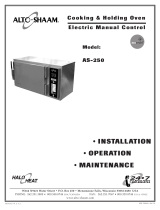
Units equipped with continuous pilot operation are fitted with
the SIT-NOVA gas valve. the gas valve has a built-in pressure
regulator and a thermo-electric ignition control for safe operation.
The valve has a step open feature (standard) for natural gas
operation. For propane, a full open feature is standard.
Explanation of the gas valve is shown in the illustration.
Step #1 - CHECKING PRESSURE
A. Turn gas connection OFF. Open gas inlet pressure
connection cap and unscrew the tap. Connect pressure
gauge at pressure tap. Read pressure.
B. If pressure measured is higher or lower than that specified
in the Pressure Table located in this manual, do
not proceed
with initial
operation.
C. Remove pressure gauge, screw in the tap and close with
protective cap.
Step #2 - ADJUST PILOT BURNER
The pilot burner assembly installed in your unit is tested prior
to shipment and does not require any adjustment. If adjustment is
desired, follow these instructions.
This step must be performed by a
qualified person only
A. Turn main power switch ON and turn the gas control knob
to PILOT.
B. Depress the knob for 30 seconds to establish the pilot flame.
C. Verify that pilot flame is well positioned and surrounding
the thermocouple.
D. If the flame requires adjustment, open the pilot cap on the
gas valve and adjust the screw to increase or decrease the
gas flow to achieve the right flame.
E. Close the pilot protective cap.
Step #3 - MANIFOLD PRESSURE ADJUSTMENT
The gas valve has a built-in pressure regulator and regulates the
manifold pressure according to specifications presented in the
Pressure Chart in this manual. The valve requires no adjustment.
However, if adjustment is desired, follow the instructions below.
This must be performed by a qualified person only.
A. Turn power and gas supply OFF.
B. Remove protective cap from outlet gas/manifold gas tap.
Unscrew, connect pressure gauge.
C. Turn main power switch ON, and turn the gas control knob
to ON.
D. Select program, set temperature and timer, and press the
START/STOP key. Follow oven operational instructions.
E. The gas valve will open and the main burner flame should
be established.
F. Measure manifold pressure. If it requires adjustment, open
the cap on the pressure regulator and adjust the screw for
increased or decreased gas pressure.
DO NOT SET THE REGULATOR TO ANY OTHER SETTING
OTHER THAN TO THE DATA SPECIFIED IN
THE
PRESSURE CHART IN THIS MANUAL.
G. Turn the gas valve OFF or to PILOT position.
H. Close the pressure regulator and manifold/outlet gas tap
with protective caps.
NOTE: If you do not understand this procedure, do not perform
any changes. Call the factory for assistance.
Step #4 - IGNITION & BURNER CHECK
For all practical reasons this will be the only check necessary
during initial operation by the installer. After the installation is
complete the oven needs to be test fired to ensure that the system is
operating properly. Follow the operating instructions posted on
the front of the unit.
The flame pattern both under hot and cold conditions should be
stable on all burner ports and there should be no lifting or blowing
after 15 seconds of operation.
See illustration in this manual for the
proper flame pattern
. There is no air shutter adjustment on these
burners and if the flame pattern does not match that shown,
contact the factory for further directions.
Make sure that the pilot burner is lighting quickly from the
electric ignitor. Then make sure that the main burner is lighting
quickly (within 4 seconds), smoothly (no harsh noise), and without
any problems. While the oven is COLD, cycle the oven ON and
OFF five times to make sure everything is working properly.
Allow the unit to heat up for 5 minutes and repeat the process.
Check the flame pattern on the burners. The flames should be
blue in color with little or no yellow in the flame. On propane gas
some yellow tipping is normal, but there should be no indication
that soot will form on the combustion chamber walls, pilot or main
burner from the yellow tipping.
Step #5 - VERIFY SEQUENCE OF OPERATION
When the Gas Combitherm is fitted with a continuous pilot and
a SIT-NOVA gas valve, the normal sequence of operation would
essentially involve igniting the pilot and switching the gas valve to
ON. The main burner would operate whenever there is demand
for heat during an active program.
However, if the continuous pilot becomes extinguished due to
interruption in gas supply or weak thermocouple signal, the
sparking or ignition system would be activated immediately to
re-ignite the pilot (the spark discharge noise can be heard). Follow
the pilot and burner ignition steps.
Operation and Care Manual #6011 • 8
1.17 - CONTINUOUS PILOT - SIT-NOVA
Pilot Gas Control
Pressure Regulator
Manifold Gas
Pressure Tap
Inlet Gas
Pressure Tap
Burner Control
Selector Knob
Installation • Section 1

CHECK LIST
✔ Transport damage?
✔ No gas hose/tube under the burner?
✔ No flexible gas line or tubing under oven?
✔ Non-combustible installation floor?
✔ Minimum clearances around oven adhered to?
✔ Unit not adjacent to heat producing equipment?
✔ Service clearance available?
✔ Gas and exhaust installation according to regulations?
✔ Water softener/conditioner installed according to regulations?
✔ Water drainage according to instructions and regulations?
✔ Shelf rack slid in completely and fastened with safety latches?
✔ Installation/operation manual and cookbook close by?
CHECKLIST
• Never store any combustible material under, on top of, or
beside this oven.
• Do not place any other heat producing appliances within 20
inches of this oven.
• Make sure the oven has plenty of ventilation air around it to
provide cooling air for the electrical and gas components.
• Do not obstruct the flow of combustion and ventilation air
around the oven.
• The bottom of the oven is the area that is used for supplying air
for combustion purposes. Keep this area clear of material which
could block the flow of air to the oven.
• Once a sufficient air supply has been established, do not reduce
the size of the room, increase the sealing of window and outside
doors, or close or remove air vents. Gas units use fresh air.
• Do not place any material on top of the oven that would
obstruct the flow of flue products. Flue gases are hot and any
material or items placed on top of, or in front of, the flue
deflector could result in a fire.
• Before servicing or cleaning this oven, disconnect the electrical
supply.
• All servicing and maintenance should be performed by a
qualified service agent.
• Clean the oven on a routine basis.
• Do not store flammable items (shower hose, plastic waste cans,
etc.) under the unit because of its excessive heat.
• A maintenance contract is highly recommended.
CHECK LIST
✕ Turn the unit OFF.
✕ Follow local regulations; if required, extinguish the pilot.
✕ Leave the door ajar.
CHECKLIST
✕ Turn main water inlet and gas supply ON.
✕ Switch unit power ON.
✕ All interior oven lights lit?
✕ Did pilot ignite correctly?
✕ Did burner ignite correctly?
CHECK LIST
Demonstrate
➡ how to light the pilot
➡ the removable drip tray
➡ the removable shelf rack with safety latches
➡ how the door magnet switch functions
CHECK LIST
Explain
➧ the indicators "no water" and "convection/steam"
➧ the cooking programs and settings
➧ the importance of preheating
➧ the handbook
CHECK LIST
Explain or demonstrate
➧ the handshower
➧ the daily cleaning process
➧ the monthly cleaning process
➧ replacing the plug-in door gaskets
➧ cleaning agents are caustic, rinse the unit well
Operation and Care Manual #6011 • 9
R
bio
Steaming Convection Superheated/Steam
Retherm Bio-Steam Core Temp. Control
INSTALLATION INSPECTION
FUNCTION
USER/OPERATOR INSTRUCTIONS
OVEN USE EXPLANATION
SERVICE PANEL USE
END OF THE DAY
CLEANING
Installation • Section 1
1.18 - INSTALLATION CHECKLISTS

Operation and Care Manual #6011 • 10
START
STOP
COOK TEMP
1
2
3
4
5
6
bio
R
POWER
ON
OFF
STEAM
BURNER
FAN
STEAM
SUPERHEATED STEAM
AND CONVECTION
CONVECTION
BIO-STEAM
RETHERM
CORE TEMP
TIMER
34° - 210°F
1° - 99°C
248° - 320°F
120° - 160°C
86° - 212°F
30° - 100°C
86° - 482°F
30° - 250°C
212° - 482°F
100° - 250°C
Automatic
COMBITHERM®
DISTR. BY ALTO-SHAAM® INC.
1 2 3
4
5
6
8 9
7
ENTER
0
HUMIDITY
PROGRAM
Low
Water
Display
(Main)
Display
(Program)
Cleaning
Program
Humidity
Control
Burner
Control
Power
Programmable
Module
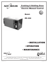
CONTROL KEY KEY DESCRIPTION
1. STEAM . . . . . . . . . . . . . . . . . . . .Indicator for steam generation status
2. BURNER . . . . . . . . . . . . . . . . . . .Indicator for main burner operation
3. FAN . . . . . . . . . . . . . . . . . . . . . . .Indicator for motor/fan operation
4. LOW WATER . . . . . . . . . . . . . . .Indicator for low water pressure or loss of water
5. STEAM . . . . . . . . . . . . . . . . . . . .Program key for automatic steam cooking 212°F (100°C)
6. SUPERHEATED STEAM . . . .Program key for combination steam &
CONVECTION . . . . . . . . . . . . .convection cooking 212-482°F (100-250°C)
7. CONVECTION . . . . . . . . . . . . .Program key for convection cooking 86-482°F (30-250°C)
8. BIO-STEAM . . . . . . . . . . . . . . . .Program key for delicate steam cooking 86-212°F
(30-100°C)
9. RETHERM . . . . . . . . . . . . . . . . .Program key for regenerating preplated food
212-482°F (100-250°C)
10. DISPLAY (MAIN) . . . . . . . . . .LED three digit display, indicates set and actual oven
temperature, cook time. Program Module will display
active program number.
11. COOK TEMP. . . . . . . . . . . . . . .Key to set oven cook temperature (F/C).
12. TIMER . . . . . . . . . . . . . . . . . . . .Key to set cook time (minutes).
13. CORE TEMP. . . . . . . . . . . . . . .Key to cook product by measuring product core
temperature.
14. UP ARROW . . . . . . . . . . . . . . .Key used to increase a selected temperature or time
15. DOWN ARROW . . . . . . . . . . .Key used to decrease a selected temperature or time
16. START/STOP . . . . . . . . . . . . . .Key to start or stop a selected cooking time.
17. HUMIDITY . . . . . . . . . . . . . . .Knob to select humidity level for Superheated Steam
program and Retherm program cooking.
18. POWER . . . . . . . . . . . . . . . . . . .Electric power switch
19. BURNER CONTROL . . . . . . .Gas burner control valve to control pilot and main
burner (located behind the swing door)
20. PROGRAMMING . . . . . . . . . .Accessory control: allows to program or presetting
up to 99 MODULE cooking programs with a
maximum of 5 steps each.
2.1 - OPERATION
CONTROL PANEL DESIGN
Operation • Section 2

(1) STEAM
Yellow: Indicates steam generation is in process.
(2) BURNER
Yellow: Activated when main burner is in operation.
(3) FAN
Yellow: Activated when motor/fan is in operation.
(4) LOW WATER
Red: Indicates when water supply line pressure is
below the minimum supply pressure or when
there is no water supply.
The following programs are available for various cooking
operations. When selection of a program is made, the indicator
light will illuminate.
(5) STEAM PROGRAM
Automatic steam cooking and cleaning program.
Oven operating temperature is preset to 212°F (100°C).
This function will steam a full or partial load of a single product.
Several different products can be combined in a single load
without transfer of flavors. When steaming multiple products,
however, individual product cooking times must be taken into
consideration. Full steam saturation is maintained automatically
regardless of the type of product, quantity, or length of time
necessary to steam.
(6) SUPERHEATED STEAM & CONVECTION
Used for roasting, baking, braising. Temperature
range is between 212°F -482°F (100°C-250°C).
Steam injection level is controlled by HUMIDITY
CONTROL (17).
This function will prove to be the most versatile and widely used
program that this oven offers. Will produce the best possible
results on widest variety of products – all within the shortest
period of time. Also offers less product shrinkage and more
moisture retention than standard convection ovens. Steam
injection is controlled manually using the humidity control knob.
In a balanced environment of moisture and heat, products retain
their natural juices and flavor.
(7) CONVECTION
Selection key for convection only cooking. Used for
grilling, baking, browning. Temperature range
available is between 86°-482°F (30°-250°C).
(8) BIO STEAM
Cooks delicate products which require gentle
steaming. Temperature range is between 86°-212°F
(30°C-100°C). Steam injection level is controlled
automatically.
The bio steam process gives the operator the capability to steam
items such as pate, terrines, mouses, flans, and seafood. Delicate
sausage casings will stay intact. This program also permits a
gentle rethermalization (reheating) of vacuum packed foods, such
as in the technique of sous-vide.
(9) RETHERM
Regenerates preplated meals or small food platters.
Temperature range available is between 212°-482°F
(100°-250°C). Steam injection level is controlled by
HUMIDITY CONTROL (17).
Refrigerated meals from chillers are brought to serving
temperature while preserving the overall quality of the meals.
Rethermalization results in less food waste due to longer shelf life
of the product under refrigeration while utilizing cook/chill
technology. Reheating of plated meals can be accomplished on a
per-order basis, ala carte, or in large volume for banquet service in
conjunction with Alto-Shaam companion holding cabinets and
interchangeable roll-in carts. This technology offers the advantage
of food cost savings as well as saving in total labor costs.
(10) DIGITAL DISPLAY
A three digit LED main display indicates set oven or product core
temperatures and cooking time. During normal operation, this
display indicates remaining cook time in minutes. When a
programming module is available, the main display can also
indicate program number, if a selection is made. The main display
also functions as an interactive screen for preset programming
information.
(11) COOK TEMPERATURE
Used to set oven temperature for all programs with
the exception of STEAM program. When selected, a
LED above this selection key will be illuminated, and
the main display will indicate the previous oven tem-
perature selection made. By using UP arrow and/ or
DOWN arrow keys, a new temperature can be set.
During normal operation for the DISPLAY to indicate actual oven
temperature, press and hold the COOK TEMP key for 3 seconds.
The actual oven temperature will be displayed as long as the
COOK TEMP is held pressed.
(12) TIMER
Used to set cooking time. When selected, a LED
above this selection key will be illuminated, and the
main DISPLAY will indicate the previous selected
time. By using the UP arrow and/or DOWN arrow
keys, a new cook time (1-199 min.) can be set.
During normal operation, remaining cook time is displayed. When
the set time runs out, the main burner and motor is switched off
and a loud buzzer is activated. The buzzer can be switched off by
pressing any of the program keys (5-9) or the START/STOP key.
Continuous time setting: Any of the cooking programs can be
executed for infinite time. This is achieved by pressing and
holding the TIMER key until "-------" is displayed.
(13) CORE TEMPERATURE
An alternative to timer operation. A cooking process
can be controlled by means of product core
temperature measurement. To set core temperature,
press CORE TEMP key. The LED above this selection
key will be illuminated, and the main display will
indicate the previous core temperature selected.
Operation and Care Manual #6011 • 11
bio
R
2.2 - SYSTEM • STATUS
2.3 - PROGRAM • FUNCTION
2.4 - DISPLAYS
2.5 - TEMPERATURE/TIME SETTING
Operation • Section 2

(14)
(15)
By using the UP arrow and/or DOWN arrow
keys, a new temperature (34°-210°F or 1°-99°C)
can be set.
During normal operation the display will indicate set core temper-
ature for 3 seconds and will automatically switch to indicate actual
product core temperature.
The cooking program will end when the product has reached the
selected core temperature. The main burner and motor is
automatically switched off and a loud buzzer is activated. The
buzzer can be switched OFF by pressing any of the program keys
(5-9) or the START/STOP key. When no key is pressed, the
buzzer will turn off after 1-2 minutes.
NOTE: When operating with Core Temperature, the Timer cannot
be set. If the Timer key (12) is pressed, the unit will switch
from Core Temperature based operation to Timer based
operation.
(16) START/STOP
Used to start or stop any of the programs (5-9)
selected. A cook program or a preset program is
started by pressing the START/STOP key.
When a program is started, System Status Indicator Lights
(3, 2 and 1; or just 3 and 2) will be illuminated. Similarly, a selected
program can be terminated any time by pressing START/STOP key.
When a program is terminated, the System Status Indicator Lights
will be switched off and the control system will retain in memory the
last program, temperature, cook time/core temperature selected.
When a cooking program is in progress and if the program
is interrupted without pressing the START/ STOP key by
opening the oven door – the main burner, fan, and if applicable,
steam generation, will be temporarily stopped. However, the
timer will continue to run. When the door is closed again, the
oven will automatically resume the program and will continue
until the cook time runs out.
This is active only with the SUPERHEATED STEAM &
CONVECTION and RETHERM programs. With all other
programs, humidity level is preset and cannot be changed.
(17) HUMIDITY CONTROL
When SUPERHEATED STEAM & CONVECTION
or RETHERM program is selected, turn the knob
manually for humidity level ranging between a
scale of 1 and 6. The steam level will be
proportionately controlled over this scale.
If the control knob is set at the lowest possible setting (i.e., 0),
no steam will be available, and the program will continue similar
to a CONVECTION program. If a preset program is activated
from the programming module, the moisture settings are not in
memory, and the user has to manually choose the moisture level
(if necessary).
(18) POWER SWITCH
When activated, provides electric power for the
system. When this knob is switched ON, the system
and the control system in the Main Display screen
will show two point/dots [. .]. This implies that the
system is ready for program selection.
Concurrent with the energization, if the pilot burner is not
ON, the
spark generator will start to generate spark at the pilot burner with
the SIT-NOVA valve.
(19) BURNER CONTROL - CONTINUOUS
PILOT SIT-NOVA Valve
This burner control valve used with continuous
pilot, located behind the swing door, controls the
operation of the pilot and main burner. The valve
is electrically operated, and the main burner can be
activated only when the POWER is switched on.
To light the pilot burner, switch the Power ON, wait and listen to
the spark discharge noise at the pilot burner.
Dial the BURNER CONTROL VALVE to PILOT position. Depress
knob a maximum of 30 seconds and view through the peep hole
for flame establishment. The peep hole is located at the lower level
of the oven. As soon as the flame is established, the spark
discharge noise will stop. At this point, continue to depress the
knob for an additional 15 seconds.
If the flame is not established within 30 seconds, switch the
POWER and dial the BURNER CONTROL VALVE to OFF
positions. Wait for 5 minutes before attempting
to relight the pilot burner.
Once lit, the pilot burner will continue to be ON even if the electric
POWER is switched OFF as long as the BURNER CONTROL
VALVE is at its PILOT position. It is highly recommended to shut
OFF the pilot burner and leave the gas valve on the OFF position at
the end of the day.
To light the main burner, dial the BURNER CONTROL VALVE to
ON. The burner operation (ON/OFF) will now be controlled by
the program START/STOP key.
To turn the pilot and main burners OFF, turn the knob to OFF
position. When the valve is at its OFF position, even if a program
is started by pressing the START/STOP key, the System Status
Light will never turn ON (yellow),
indicating the main burner is not
switched ON.
Similarly, if the pilot burner is not switched ON, even if a program
is started by pressing the START/STOP key, the System Status
Light will never turn ON (yellow)
indicating the main burner is not
switched ON.
Operation and Care Manual #6011 • 12
START
STOP
2.6 - HUMIDITY
1
2
3
4
5
6
2.7 - MAIN COMBITHERM CONTROLS
POWER
ON
OFF
Operation • Section 2

(19) BURNER CONTROL - INTERMITTENT PILOT
HONEYWELL Valve
This burner control valve used with intermittent pilot, located
behind the swing door, controls the operation of the pilot and main
burner. The valve is electrically operated, and the main burner can
be activated only when the POWER and the Gas Control Valve
switch are ON.
The pilot burner is lit automatically when necessary and does not require
user action.
The burner operation (ON/OFF) will be controlled by the program
START/STOP key.
During normal operation, the electronic control will try three times
to light the pilot/main burner. If ignition attempts fail, the control
will automatically shut the gas OFF. If this occurs, verify the
operating conditions are correct and switch OFF the Power to reset
and restart.
To turn the pilot and main burners OFF, switch the Power to
OFF position. The intermittent pilot control system will operate
without any user intervention and normally uses a "hands off"
policy.
(20) PROGRAMMABLE
CONTROL/MODULE
This accessory allows the user to preset
or program the entire Combitherm
operation. Thus, once programmed to
cook certain product, say chicken, at the
convenience of a single program key,
the user can start and perform the entire
program.
This module would allow the user to
program in up to 99 preset programs,
each program with a maximum of 5
steps. For example, program #1 could
contain the following sequence:
Step #1 - Superheated Program at Temp. 250°F, time = 3 min.
Step #2 - Superheated Program at Temp. 325°F, time = 22 min.
Step #3 - Convection Program at Temp. 325°F, time = 4 min.
Step #4 - Convection Program at Temp. 250°F, time = 4 min.
Step #5 - Convection Program at Temp. 200°F, time = 2 min.
CLEANING PROGRAM
Each program module includes a built-in automatic
cleaning program. This program is preset at the
factory to facilitate the cleaning process at the end of
the day. Explanation on how to use this feature is
provided in the Maintenance Section of this manual.
GENERAL OPERATION • HELPFUL HINTS
➽ When using the hand sprayer, make sure the power switch is in
the OFF position.
➽ Before using the hand sprayer, wait until the cooking
compartment has cooled down to at least 122°F (50°C).
➽ Severe damage can occur if cold water is used on a hot oven.
➽ Never use the oven cleaner or the hand sprayer to clean the
outer surface of the oven.
➽ Related products with similar cooking/baking guidelines
(program, time, temperature) can be cooked together.
SAFETY PRECAUTIONS • STEAM
➽ During steaming, for safe release of the cooking compartment
steam, initially open the door approximately 2" (50mm) only.
Stand behind the door as the hot steam is released.
➽ Before opening the oven door, always press the STOP key and
wait a few seconds to allow the fan to stop rotating.
OVEN START-UP
1. Make certain main gas and water supply and exhaust
ventilation are ON.
2. Turn Power Selector switch ON.
3. Turn Burner Control knob to PILOT. Press knob inward for
30 seconds to light pilot burner
(only with units having
Continuous Pilot - SIT-NOVA valve).
NOTE: If pilot is not established, turn Power selector and Burner
Control OFF and wait for 5 minutes before lighting.
4. For units with Intermittent Pilot (Honeywell Valve):
No action is necessary.
5. For units with Continuous Pilot (SIT-NOVA Valve):
Turn Burner Control knob to ON.
OVEN OPERATION
Step #1
- SELECT PROGRAM
STEAM
Steam • Clean
SUPERHEATED STEAM & CONVECTION
Roast • Bake • Brown
CONVECTION
Bake • Brown
BIO-STEAM
Delicate Steam
RETHERM
Reheat Plated Meals
Operation and Care Manual #6011 • 13
1 2 3
4
5
6
8 9
7
ENTER
0
PROGRAM
2.8 - BASIC OPERATION
bio
R
Operation • Section 2

Step # 2 SET COOK TEMPERATURE
NOTE: Cook Temperature cannot be set in the Steam Program Mode.
To set temperature, push Cook Temp key and use or
keys to set a temperature within the range specified for the
program mode selected.
Step # 3 SET TIMER/CORE TEMPERATURE
TIMER
Push Timer key and use or keys for selection of
required cook time. If continuous time setting is desired, press
Timer key until "----" is displayed.
CORE TEMPERATURE
As an alternative to timer operation, use this option
in any program mode to cook by sensing
internal product temperature.
• Insert probe in product.
• Press Core Temp key and or keys to
set the required internal product temperature.
Step #4 SET HUMIDITY LEVEL
Humidity setting can only be used in Superheated Steam and
Retherm programs.
Turn the Humidity Control dial to a setting between
1 and 6.
Step #5 PROGRAM START/STOP
Press key to Start or Stop program.
The display will always indicate the remaining cook time.
To check oven temperatures, press Cook Temp key for 3
seconds; the display will indicate actual temperature. At the end
of the program, a buzzer will sound for a period of 70 seconds.
The buzzer can be immediately deactivated by pressing any
program key.
Step #6 SHUT-DOWN
After daily use, set the Burner Control knob (with SIT-
valve ONLY) and Power Selector switch to the "OFF" position.
Selector switch to the "OFF" position.
UNLOCKING AND LOCKING COOKING PROGRAMS
Use this feature to lock one or all of the five cooking programs to a
preselected cook temperature and core temperature or cook time.
UNLOCKING A LOCK STATUS
➽ Switch POWER (18) knob "ON" and the main DISPLAY (10) will
be steadily lit [ . . ], if locked. The buzzer may or may not be
active. If the buzzer is active do not try to cancel.
➽ Simultaneously press the COOK TEMP (11) and the TIMER (12)
keys . The DISPLAY (10) will indicate the locked status "Loc".
➽ To Unlock using the UP key (14) or DOWN key (15) select "unL"
and press the START/STOP key (16), until the main DISPLAY
(10) begins to flash [ . . ].
LOCKING PROGRAMS
➽ Select each of the five program keys (5-9) .
➽ Set a desired cook temperature and/or core temperature or
cook time using the keys (11-15) for each program and press
START/STOP key (16) for each completed program.
➽ Switch POWER knob (18) OFF. AFter a few moments, switch
POWER knob (18) back ON.
➽ Simultaneously press the COOK TEMP key (11) and the
TIMER (12) keys . DISPLAY (10) will indicate "unL".
➽ Using the UP key (14) or DOWN key (15) select "Loc" and press
the START/STOP key (16) until the main DISPLAY (10)
becomes steadily lit [ . . ].
All the program parameters such as temperature, time or core
temperature chosen for the various programs are now locked and
cannot be changed until they are unlocked again.
OPERATING A LOCKED SYSTEM
Once one or more of the cooking programs are preset and locked,
the user should be instructed to follow the operating procedure
outlined below.
➽ Start the Combitherm system according to the procedure
discussed in the Basic Operation Section 2.8.
➽ Select a locked cooking program by pressing the program
selection key (5-9) and if desired, insert the Core Temperature
Control Probe into the product.
➽ Press START/STOP key (16) to execute the locked program.
Changing programs while the locked system is in operation is
only possible by pressing the START/STOP key (16) to leave one
pro-gram and again to start the next. If a locked program is
selected and if program choices keys such as COOK TEMP (11)
or TIMER (12) or CORE TEMP (13) are pressed, set parameters will
be displayed.
After the locked cooking time runs out or when cooking process
is completed, the buzzer will sound and will switch the fan and
burner off.
START
STOP
1
2
3
4
5
6
Operation and Care Manual #6011 • 14
2.9 - ADVANCED COMBITHERM OPERATION
Operation • Section 2

SWITCHING BETWEEN CELSIUS AND FAHRENHEIT
TEMPERATURE SYSTEMS
Shut POWER (18) to the unit "OFF" and wait about 2 minutes. It is
very important to wait for 2 minutes before you proceed further.
➽ Simultaneously press COOK TEMP key (11), TIMER key (12)
and the START/STOP key (16) and switch the electric POWER
switch (18) from "OFF" to "ON" position. The main DISPLAY
(10) will read "S1" or similar service program number.
➽ Using the UP and/or DOWN key, choose the service program
"S2" to change temperature systems. Press START when the
main DISPLAY (10) reads "S2".
➽ The main DISPLAY (10) will either show a "0" or "1". Using the
UP and/or DOWN arrow keys, choose 0 for Celsius (C) or 1 for
Fahrenheit (F) temperature system.
➽ Press START/STOP key (16) to confirm the selection made. The
controller is now ready for the chosen temperature system.
Do not choose any other service program or alter any other
settings. This will result in changes to factory settings and could
affect the performance of the Combitherm oven.
If your Combitherm oven is equipped with the programmable
module (20), read and familiarize yourself with this section. The
program module allows presetting or programming up to 99
cooking sequences into memory. Each program or cooking
sequence can store up to 5 cook steps. The program module also
includes a factory set auto cleaning program. This section
describes how to program a cooking sequence and how to operate
the oven using program numbers.
PROGRAMMING COOKING SEQUENCE(S)
INTO MEMORY
Unit must be in UnLock Mode for this Procedure.
A. POWER-UP
To program first power-up from the OFF state by turning the
POWER (18) knob to ON. The main Display (1) should begin
flashing two points/dots [ . . ]. If the dots are not flashing, you
are in locked mode. Unlock and restart.
B. INITIATE PROGRAM MODE
Push UP and DOWN arrow
keys simultaneously for
approximately 5 seconds. The
main Display (10) will show the
last program number (e.g. 15).
The LED by the program
display will be lit and the
program display will show the
number of program steps for
program number 15 e.g. 5.
C. SELECT NEW PROGRAM
NUMBER
Choose a new program number
that you desire for the cooking
sequence you want to program.
For example, to enter a cooking
sequence for program number 1,
press number 1 key.
The main DISPLAY (10) will show" P1" and the program display
will show 0 steps or the maximum number of steps previously
entered. Now press the ENTER key at the program module. The
main DISPLAY (10) will either go blank or show previously stored
parameters. The program display will now show "1" for step
number 1.
D. ENTER STEP 1 COOKING PARAMETERS
Press number 1 key choosing step 1. The main DISPLAY (10)
will now be blank and the program display will show "1". Now
select the cooking parameters, i.e., cook program (steam,
combination, convection, etc.) temperature, time or core
temperature.
(Review Basic Operation Procedures to understand
how to enter specific temperature or time.)
E. ENTER STEP 2/3/4/5 COOKING PARAMETERS
Press the next sequential step number (2/3/4/5) key. The main
DISPLAY (10) will remain blank and the program display will
show the chosen step number (2/3/4/5). Now select the
cooking parameters, i.e., cook program (steam, combination,
convection, etc.), temperature, time or core temperature.
NOTE: You can enter the steps only in a sequential order. Thus, you
cannot enter 4 before 1/2/3 have been completed.
F. COMPLETE PROGRAMMING
After entering all the parameters for various steps, press
ENTER and hold until you hear a "beep" from the buzzer. This
indicates that the data is now stored in memory.
NOTE: You are still in program mode and the LED by the side of
program display is still ON.
G. ENTER ANOTHER PROGRAM OR COOKING SEQUENCE
If you choose to enter another program sequence, you can do
now. Follow the procedures B through F above.
H. EXIT PROGRAM MODE
Once all programming is completed, to exit the program mode,
press START/STOP key. You will not hear the buzzer,
however, you will notice that the main DISPLAY (10) will
return to flashing does [ ... ], and the program display will turn
blank.
Make a record of the program and post it in front of the oven. It is also
recommended to lock the control for added protection (see Section 2.9 for
locking procedure).
EDITING/DELETING A PROGRAM STEP
Unit must be in UnLock Mode for this Procedure.
If you want to edit or delete a previously entered program step,
follow these procedures.
1. Initiate program mode, select the program number and select
the program step to modify (repeat procedures A through D
above.
2. EDIT: To make a change in the cooking parameters
(temperature, time, etc.), select the parameter for that step and
using the UP and/or DOWN key choose a different parameter.
3. DELETE: To delete a step, after choosing the step number,
press START/STOP key. All parameters for the chosen step
and the subsequent steps will now be deleted from memory.
Operation and Care Manual #6011 • 15
START
STOP
COOK TEMP
CORE TEMP
TIMER
34° - 210°F
1° - 99°C
1 2 3
4
5
6
8 9
7
ENTER
0
PROGRAM
P15
Operation • Section 2
/