Page is loading ...

Isolated Current Sensing Module with ACPL-C79X
User Guide
Introduction
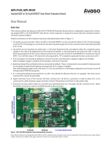
The ACPL-C79x isolated current sense evaluation module,
shown in Figure 1, is pin-to-pin compatible with several
Hall eect current transducers. The evaluation module has
a ±1% (ACPL-C79A) isolation amplier gain accuracy, but
the ACPL-C79x is also oered with a ±0.5% (ACPL-C79B)
or ±3% (ACPL-C790) specication. The ACPL-C79B/C79A/
C790 isolation ampliers were designed for current and
voltage sensing in electronic power converter, motor
drive and renewable energy applications.
For many compact power drive designs, a shunt resistor
plus isolation amplier measurement solution has many
benets over traditional Hall eect current sensors. The
benets include a smaller, lower prole component with
better linearity, lower temperature drift, and lower cost.
As shown in Figure 2, the evaluation module is 20 mm by
16 mm and 24 mm high.
Key components, including the shunt resistor and isola-
tion amplier, are available in small surface mount pack-
ages. Some designers who are familiar with current trans-
ducers can nd using the shunt resistor plus optically
isolated isolation amplier a challenge. This evaluation
module makes the evaluation quick and very easy.
The evaluation module is pin-to-pin compatible with se-
lected Hall eect current transducers, such as LEM’s LTS
6-NP, LTS 15-NP, LTS 25-NP, CAS 6-NP, CAS 15-NP, and CAS
25-NP models
[1]
. With the evaluation module, designers
using the LTS and CAS devices will nd it easy to evaluate
and compare the ACPL-C79X based current sensing solu-
tion against their existing Hall eect current transducer
solutions. For example, a designer can simply remove an
LTS 15-NP device and plug in the evaluation module and
start a quick evaluation.
Figure 1. ACPL-C79x isolated current sense evaluation module
Figure 2. Current sense isolation amplier evaluation module
ACPL-C79A
DC-DC converter
Shunt Resistor
PCB1
PCB2
Note 1. Products of LEM Holding SA

For product information and a complete list of distributors, please go to our web site: www.avagotech.com
Avago, Avago Technologies, and the A logo are trademarks of Avago Technologies in the United States and other countries.
Data subject to change. Copyright © 2005-2012 Avago Technologies. All rights reserved.
AV02-3742EN - August 7, 2012
Figure 3. The Evaluation module schematic
Schematic
The evaluation module circuit schematic is show in Figure
3. The evaluation module is made from two printed circuit
boards (PCBs): PCB1 and PCB2. PCB1 has the shunt resis-
tor and two header connectors to form a current path; a
third header connector is used as an interface. PCB2 has
an ACPL-C79A isolation amplier (±1% gain accuracy) and
an isolated DC-DC converter. The two PCBs are assembled
with header connectors P4 and P5.
AC or DC current through shunt resistor R1 results in a
voltage that is proportional to current. This voltage is l-
tered by the anti-aliasing lter formed by R2, R3 and C1
and then sensed by the dierential input ACPL-C79A. A
dierential output voltage that is proportional to the in-
put voltage is created on the other side of the optical iso-
lation barrier.
Following the isolation amplier, an OPA237 congured
as a dierence amplier converts the dierential signal
to a single-ended output. This stage can be congured to
further amplify the signal, if required, and form a low-pass
lter to limit the bandwidth.
In the evaluation module, the dierence amplier is de-
signed for a gain of 1 with a low-pass lter corner frequen-
cy of 234 kHz. Resistors R6 and R7 can be selected for a
dierent gain. The bandwidth can be reduced by adding
capacitors to the positions of C6 and C8.
With the ACPL-C79A gain of 8.2, the overall transfer func-
tion is:
Vout = I × R1 × 8.2 + Vref .
The output signal, Vout, is then connected to the next
stage, such as a signal processor, through the P7 header
connector, pin 3.
Shunt Resistor and Current Range
The shunt resistor in this module is xed at 10 milliohm.
The appropriate current measurement range is about 15
A
RMS
. This is calculated from the nominal input range of
±200 mV of the ACPL-C79A. The ACPL-C79x species a
full scale input range of ±300 mV, which allows accurate
overload current detection of up to 21 A
PEAK
. Because the
evaluation module does not provide good heat dissipa-
tion for the shunt resistor due to small PCB size, limit cur-
rent to 10 A
RMS
during evaluation or for a quick functional
check at 15 A
RMS
. For a detailed performance evaluation,
a PCB with proper layout for the shunt resistor and other
components is recommended.
Power Supplies
The evaluation module works on a single 5 V supply,
which can be the same power supply for the signal pro-
cessor and controller device connected through pin 1 and
2 of P7.
The isolated DC-DC converter (U1 in Figure 3) is included
in the evaluation module to power up the signal input
side of the ACPL C79A; this makes the evaluation an easy
plug-and-play operation. However, to make an ACPL C79A
based solution cost eective in mass production, the 5 V
supply would usually be supplied by a oating power sup-
ply, which in many applications could be the same supply
that is used to drive the high-side power transistor. A sim-
ple three-terminal voltage regulator will provide a stable
voltage. Another method is to add an additional winding
to an existing transformer to produce a 5 V supply.
0.47uF
C3
10R,1%
R2
0.47uF
C4
GND2GND1
100nF
C2
GND1
100nF
C5
GND2
22nF
C1
10R,1%
R3
GND1
GND2
10K,1%
R4
10K,1%R5
NMC8
68pFC9
10K,1%R7
0.1uFC10
GND2
68pF
C7
10K,1%
R6
NM
C6
Vref
GND2
1K,1%
R9
1K,1%
R8
1uF
C11
Vref
GND2 GND2
VDD2
VDD2
GND2
WSR3R0100F
R1
R01, 3W
-Vin
1
+Vin
4
+Vout
5
-Vout
7
U1
NKE0505DC
1
2
3
P1
Header 3
1
2
3
P2
Header 3
1 2
3 4
P3
Leave Blank
1
2
3
P7
Header 3
1 2
3 4
P4
MHDR2X2
V+
0V
Out
PCB2PCB1 PCB1
Vinp
Vinn
VDD1
1
VIN+
2
VIN-
3
GND1
4
GND2
5
VOUT-
6
VOUT+
7
VDD2
8
U2
ACPL-C79X
3
2
6
7
4
8
1
5
U3
OPA237UA
VDD1
Vout
1
2
34
P6
Leave Blank
12
3
4
P5
MHDR2X2
Note *: Dotted lines denote header pin connections.
*
*
*
*
*
I
/