Page is loading ...

WARNING - RISK OF ELECTRIC SHOCK. DISCONNECT
MAIN POWER AT FUSE OR CIRCUIT BREAKER
BEFORE INSTALLING OR SERVICING THE FIXTURE.
LED5” & 6” RETROFIT TRIM INSTALLATION
INSTRUCTIONS - MODEL CER6730M
QUESTIONS? CALL TOLL
FREE 1-877-527-0313
Please read carefully and save these instructions
as you may need them at a later date.
GENERAL: All electrical connections must be in accordance
with local and National Electrical Code (N.E.C.) standards. If
you are unfamiliar with proper electrical wiring connections
obtain the services of a qualified electrician.
Remove the trim from the box and make sure that no parts are
missing by referencing the PARTS illustrations.
THIS RETROFIT ASSEMBLY IS ACCEPTED AS A
COMPONENT OF A LED LUMINAIRE WHERE THE
SUITABILITY OF THE COMBINATION SHALL BE
DETERMINED BY CSA OR CANADIAN AUTHORITIES
HAVING JURISDICTION.
_________________________________________________
WARNING- RISK OF FIRE OR ELECTRIC SHOCK
FOR USE WITH HOUSING MODELS: INCANDESCENT
HOUSINGS – COMMERCIAL ELECTRIC HBR5ICAT,
HBR5ICRAT, HBR5, HBR5R, HALO H5T, H5RT, H5ICT,
H5RICAT, C7IC, C7ICR, C7ICA, C7ICRA, C7, C7R, C7S,
HBR5000SIC; HALO H7ICT, H7RICT, H7ICAT, H7RICAT, H7T,
H7RT, H27ICT, H27T, H27RT, H750ICAT, H750RICAT;
CORDELIA X5LICAT, X5LICRAT, HBR7LICAT, HBR7LICRAT;
CAPRI CR1, CRR1; DMF DH6ICATQ, DH6ICRATQ; ELCO
EL5ICA, EL5RICA; LITHONIA L5, L5R, EL7ICA, EL7RICA;
ELITE B5, B5R, B5IC, B5RIC, B6IC, B6RIC; JUNO IC22, IC22R;
LITHONIA L7X, L7XR; NORA NHIC-17QAT, NHRIC-17QAT;
PROGRESS P187-TG, P87-AT, P184-TG, P84-AT; SEA GULL
11018, 11028; THOMAS PS1, PS1-RM. HALO LED HOUSINGS
– H550ICAT, H550RICAT H750ICAT, H750RICAT.
• Do not alter, relocate, or remove wiring, lampholders, power
supply, or any other electrical component. Installation of the
retrofit assembly requires a person familiar with the
construction and operation of the luminaire’s electrical
system and the hazard involved. If not qualified, do not
attempt installation. Contact a qualified electrician.
• Do not make or alter any open holes in an enclosure of
wiring or electrical components during kit installation.
• To prevent wiring damage or abrasion, do not expose wiring
to edges of sheet metal or other sharp objects.
____________________________
ASSEMBLY AND INSTALLATION
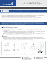
1. If using a 5 inch housing, loosen the screws on the
TORSION SPRINGS (and slide the brackets inward. Re-
tighten screws to secure TORSION SPRINGS in place. (FIG.
2)
INCANDESCENT HOUSINGS
1. Unscrew the WING NUT inside the CAN to detach the
SOCKET BRACKET from the CAN. Disengage the
SOCKET from the SOCKET BRACKET. (FIG. 3)
2. Thread the SOCKET ADAPTER into the SOCKET. (FIG. 4)
5 in. – 6 in.
PARTS
SOCKET ADAPTER
ASSEMBLY
RETROFIT TRIM
COMPATIBLE HOUSING
DIMENSIONS
FIG. 2
FIG. 3 FIG. 4
5 in. – 7 in.
OR

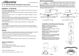
3. Plug the FEMALE CONNECTOR of the RETROFIT TRIM
onto the MALE CONNECTOR of the SOCKET ADAPTER
ASSEMBLY. (FIG. 5)
4. If using TORSION SPRINGS, squeeze both TORSION
SPRING arms together and insert into the TORSION
SPRING SLOTS (or C-CLIPS) of the CAN. (FIG. 6)
5. Tuck all wires into the CAN and carefully push the
RETROFIT TRIM into CAN. (NOTE: To provide enough
room in shallow cans, carefully position SOCKET ADAPTER
and SOCKET adjacent to the side of the LED DRIVER prior
to inserting the RETROFIT TRIM into the CAN.) (FIG. 4 & 6)
LED HOUSINGS
1. Plug the FEMALE CONNECTOR of the RETROFIT TRIM
onto the MALE CONNECTOR of the HALO HOUSING. (FIG.
5)
2. If using TORSION SPRINGS, squeeze both TORSION
SPRING arms together and insert into the TORSION
SPRING SLOTS (or C-CLIPS) of the CAN. Tuck all wires
into the CAN and carefully push the RETROFIT TRIM into
CAN. (FIG. 6)
FIG. 5
FIG. 6
C D L
• Tc
MODEL:
CDLPS150R10
Dimmable LED Driver
CAUTION:
Risk of Electric Shock
Damp Locations
For Indoor Use Only
____
_ _ _
AC INPUT:
120 Vac/Max 200 mA
60Hz PF >0.9
L-BLACK
N-WHITE
Made in China
DC OUTPUT:
50-66V
Red:+ Black:
Regulated current:
150 mA
ATTENTION:
RISQUE DE CHOC POUR
EMPLACEMENTS
SECS SEULEMENT
USAGE INTÉRIEUR
SEULEMENT

________
DIMMING
Dimming performance may depend on the
dimmer, the dimmer range adjustment
setting (for dimmers with brightness range
adjustments), the wiring method, and/or the
number of LED modules installed onto the
dimmer circuit.
For a complete list of compatible dimmers,
please look up the item number listed on
the cover of this instruction manual at
http://www.homedepot.com/.
_____________________________
FIVE-YEAR LIMITED WARRANTY
Commercial Electric
warrants this product to be free from
defects in material and workmanship for five years from the
original date of purchase by the consumer. This warranty is
limited to the counter replacement at the time of purchase, with
the original purchase receipt. Com mercial Electric
will not
be liable for the loss or damage of any kind, incidental or
consequential damages of any kind, whether based on
warranty contract or negligence, and arising in connection with
the sale, use or repair of the product claimed to be defective.
Some states do not allow the exclusion or limitation of
incidental or consequential damages so the above limitation
may not apply to you. This warranty gives you specific legal
rights and you may also have other rights, which vary from
state to state. Misuse, accident, improper installation or
maintenancewill also void the warranty.
_____________________________
This device complies with part 15 of the FCC Rules. Operation is
subject to the following two conditions:
1.This device may not cause harmful interference, and
2.This device must accept any interference received, including
interference that may cause undesired operation.
NOTE: This equipment has been tested and found to comply
with the limits for a Class B digital device, pursuant to Part 15 of
the FCC Rules. These limits are designed to provide reasonable
protection against harmful interference in a residential installation.
This equipment generates, uses and can radiate radio frequency
energy and, if not installed and used in accordance with the
instructions, may cause harmful interference to radio
communications. However, there is no guarantee that
interference will not occur in a particular installation. If this
equipment does cause harmful interference to radio or television
reception, which can be determined by turning the equipment off
and on, the user is encouraged to try to correct the interference
by one or more of the following measures:
• Reorient or relocate the receiver antenna.
• Increase the separation between the equipment and
receiver.
• Install the product onto on a circuit different from that to
which the receiver is connected.
• Consult with the dealer or an experienced radio/TV
technicianfor help.
CAUTION: Any changes made to the electronics circuit will void
this equipment’s compliance with Part 15 of the FCC Rules and
should not be operated.
Brand
Series
Model #
Wiring
Version
Code
Max
Luminaires
Dimming
Range
Lutron
Ariadni/Toggler C.L
AYCL-153P
3-Way
T4, T8
13
5% - 100%
TGCL-153P
Diva C.L
DVCL-153P
Skylark C.L
SCL-153P
Skylark Contour
C.L
CTCL-153P
Lumea C.L
LGCL-153P
Maestro C.L
MACL-153M
3-Way
2014
13
10% - 100%
MSCL-VP153M
single/multi
T2
13
10% - 100%
MSCL-OP153M
single/multi
MRF2-6CL
NA
M6
13
10% - 100%
Nova T
NTCL-250
single
BR Y02
22
10% - 100%
Grafik T
GT-150
single
T6
13
10% - 100%
Grafik T RF
GTJ-150
single
M6
13
9% - 100%
Caseta
PD-6WCL
NA
SD11
13
5% - 100%
Leviton
Decora
DSL06-1L
3-Way
NA
27
24% - 100%
Illuma Tech
IPL06-10
3-Way
NA
13
9% - 100%
Sureslide
6672-1L
single
NA
13
17% - 100%
Sureslide
6674-P0
3-Way
NA
13
10% - 100%
POWER
IN
TRIAC
DIMMER
WHITE
BLACK
BARE/
GREEN
WHITE
BLACK
BARE/
GREEN
FIXTURE
OUTPUT WIRE

ADVERTENCIA: RIESGO DE DESCARGA
ELÉCTRICA. DESCONECTE EL SUMINISTRO
ELÉCTRICO DE LA CAJA DE FUSIBLES O LOS
INTERRUPTORES DE CIRCUITO ANTES DE
INSTALAR O DAR MANTENIMIENTO A LA UNIDAD.
INSTRUCCIONES PARA LA INSTALACIÓN DEL
ADAPTADOR DECORATIVO LED DE 5” y 6” -
MODELO CER6730M
¿PREGUNTAS? LLAME
GRATIS AL 1-877-527-0313
Lea cuidadosamente y guarde estas instrucciones ya
que podría necesitarlas más adelante.
GENERAL: Todas las conexiones eléctricas deben realizarse
conforme a las normas locales y al Código Eléctrico Nacional (N.E.C.
por sus siglas en inglés). Si no está familiarizado con las conexiones
adecuadas de cableado eléctrico obtenga los servicios de un
electricista calificado.
Retire el adaptador decorativo de la caja y asegúrese de tener todas
las piezas comparándolas con las ilustraciones de las PARTES.
ESTE ADAPTADOR DECORATIVO SE ACEPTA COMO UN
COMPONENTE DE LUMINARIA LED DONDE LA APTITUD DE LA
COMBINACIÓN SERÁ DETERMINADO POR CSA O
AUTORIDADES CANADIENSES COMPETENTES.
_______________________________________________
ADVERTENCIA - RIESGO DE INCENDIO O
DESCARGA ELÉCTRICA
PARA USO CON MODELOS DE CAJAS DE LUZ EMPOTRADAS-
COMMERCIAL ELECTRIC HBR5ICAT, HBR5ICRAT, HBR5,
HBR5R, HALO H5T, H5RT, H5ICT, H5RICAT, C7IC, C7ICR, C7ICA,
C7ICRA, C7, C7R, C7S, HBR5000SIC; HALO H7ICT, H7RICT,
H7ICAT, H7RICAT, H7T, H7RT, H27ICT, H27T, H27RT, H750ICAT,
H750RICAT; CORDELIA X5LICAT, X5LICRAT, HBR7LICAT,
HBR7LICRAT; CAPRI CR1, CRR1; DMF DH6ICATQ, DH6ICRATQ;
ELCO EL5ICA, EL5RICA; LITHONIA L5, L5R, EL7ICA, EL7RICA;
ELITE B5, B5R, B5IC, B5RIC, B6IC, B6RIC; JUNO IC22, IC22R;
LITHONIA L7X, L7XR; NORA NHIC-17QAT, NHRIC-17QAT;
PROGRESS P187-TG, P87-AT, P184-TG, P84-AT; SEA GULL
11018, 11028; THOMAS PS1, PS1-RM. CAJAS DE LUZ
EMPOTRADAS LED; HALO – H550ICAT, H550RICAT H750ICAT,
H750RICAT.
• No altere, reubique, o elimine cableado, alimentación, o
cualquier otro componente eléctrico. La instalación de la ase
amble de reforzamiento requiere una persona familiarizada con
la construcción y operación del sistema eléctrico de la luminaria
y el riesgo involucrado.
• No haga ni alterar ningún agujero en la caja de cables o
componentes eléctricos durante la instalación del kit.
• Para evitar daños de abrasión en el cableado, no exponga el
cableado a los bordes de chapa u otros objetos filosos.
________________________
MONTAJE E INSTALACIÓN
1. Si utiliza un ALOJAMIENTO de 5 pulgadas, afloje los
TORNILLOS de las ABRAZADERAS y deslice los soportes hacia
el interior. Apriete de nuevo los TORNILLOS para asegurar el
soporte de resorte en su lugar. (FIG. 2)
CAJAS INCANDESCENTES
1. Remueva la TUERCA MARIPOSA ubicada dentro del
ALOJAMIENTO DE LA LÁMPARA para soltar la ABRAZADERA
DEL PORTALÁMPARAS. Desconecte el PORTALÁMPARAS de
la ABRAZADERA DEL PORTALÁMPARAS. (FIG. 3)
2. Inserte el ADAPTADOR DEL PORTALÁMPARAS en el
PORTALÁMPARAS. (FIG. 4)
5 in. – 6 in.
PARTES
UNIDAD DEL ADAPTADOR
DEL PORTALÁMPARAS
ADAPTADOR
DECORATIVO
DIMENSIONES DE LA CAJA
FIG. 2
FIG. 3 FIG. 4
5 in. – 7 in.
O
/