Page is loading ...

WARNING - RISK OF ELECTRIC SHOCK. DISCONNECT MAIN
POWER AT FUSE OR CIRCUIT BREAKER BEFORE
INSTALLING OR SERVICING THE FIXTURE.
LED 5” & 6” RETROFIT TRIM
INSTALLATION INSTRUCTIONS
MODELS CER6730N & CER6733N
QUESTIONS? CALL TOLL
FREE 1-877-527-0313
Please read carefully and save these instructions as
you may need them at a later date.
GENERAL: All electrical connections must be in accordance with local
and National Electrical Code (N.E.C.) standards. If you are unfamiliar
with proper electrical wiring connections obtain the services of a
qualified electrician.
Remove the trim from the box and make sure that no parts are missing
by referencing the PARTS illustrations.
THIS RETROFIT ASSEMBLY IS ACCEPTED AS A COMPONENT OF
A LED LUMINAIRE WHERE THE SUITABILITY OF THE
COMBINATION SHALL BE DETERMINED BY CSA OR CANADIAN
AUTHORITIES HAVING JURISDICTION.
_________________________________________________
WARNING- RISK OF FIRE OR ELECTRIC SHOCK
FOR USE WITH HOUSING MODELS: INCANDESCENT HOUSINGS –
COMMERCIAL ELECTRIC HBR5ICAT, HBR5ICRAT, HBR5, HBR5R,
HALO H5T, H5RT, H5ICT, H5RICAT, C7IC, C7ICR, C7ICA, C7ICRA,
C7, C7R, C7S, HBR5000SIC; HALO H7ICT, H7RICT, H7ICAT,
H7RICAT, H7T, H7RT, H27ICT, H27T, H27RT, H750ICAT, H750RICAT;
CORDELIA X5LICAT, X5LICRAT, HBR7LICAT, HBR7LICRAT; CAPRI
CR1, CRR1; DMF DH6ICATQ, DH6ICRATQ; ELCO EL5ICA, EL5RICA;
LITHONIA L5, L5R, EL7ICA, EL7RICA; ELITE B5, B5R, B5IC, B5RIC,
B6IC, B6RIC; JUNO IC22, IC22R; LITHONIA L7X, L7XR; NORA NHIC-
17QAT, NHRIC-17QAT; PROGRESS P187-TG, P87-AT, P184-TG,
P84-AT; SEA GULL 11018, 11028; THOMAS PS1, PS1-RM. HALO
LED HOUSINGS – H550ICAT, H550RICAT H750ICAT, H750RICAT.
• Do not alter, relocate, or remove wiring, lampholders, power supply,
or any other electrical component. Installation of the retrofit
assembly requires a person familiar with the construction and
operation of the luminaire’s electrical system and the hazard
involved. If not qualified, do not attempt installation. Contact a
qualified electrician.
• Do not make or alter any open holes in an enclosure of wiring or
electrical components during kit installation.
• To prevent wiring damage or abrasion, do not expose wiring to
edges of sheet metal or other sharp objects.
____________________________
ASSEMBLY AND INSTALLATION
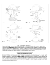
1. If the installed housing does not have TORSION SPRING SLOTS
or C-CLIPS (FIG. 4) then remove the SCREWS securing the
TORSION SPRINGS to the HEATSINK. Attach the FRICTION
BLADES (included) to the same location using the SCREWS that
were previously removed. (FIG. 1)
2. If using a 5 inch housing, loosen the screws on the TORSION
SPRINGS (and slide the brackets inward. Re-tighten screws to
secure TORSION SPRINGS in place. (FIG. 2)
INCANDESCENT HOUSINGS
1. Unscrew the WING NUT inside the CAN to detach the SOCKET
BRACKET from the CAN. Disengage the SOCKET from the
SOCKET BRACKET. (FIG. 3)
2. Thread the SOCKET ADAPTER into the SOCKET. (FIG. 4)
PARTS
SOCKET ADAPTER ASSEMBLY
RETROFIT TRIM
COMPATIBLE HOUSING
DIMENSIONS
5 in. – 7 in.
5 in. – 6 in.
OR

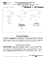
1. Plug the MALE CONNECTOR of the SOCKET ADAPTER to
the FEMALE CONNECTOR of top of the RETROFIT TRIM.
(FIG. 5)
3. If using TORSION SPRINGS, squeeze both TORSION
SPRING arms together and insert into the TORSION SPRING
SLOTS (or C-CLIPS) of the CAN. (FIG. 6A)
5. Tuck all wires into the CAN and carefully push the RETROFIT
TRIM into CAN. (NOTE: To provide enough room in shallow
cans, carefully position SOCKET ADAPTER and SOCKET
adjacent to the side of the LED DRIVER prior to inserting
the RETROFIT TRIM into the CAN.) (FIG. 6A or 6B)
LED HOUSINGS
1. Plug the MALE CONNECTOR of the SOCKET ADAPTER to
the FEMALE CONNECTOR of top of the RETROFIT TRIM.
(FIG. 5)
2. If using TORSION SPRINGS, squeeze both TORSION
SPRING arms together and insert into the TORSION SPRING
SLOTS (or C-CLIPS) of the CAN. (FIG. 6A)
3. Tuck all wires into the CAN and carefully push the RETROFIT
TRIM into CAN. (FIG. 6A or 6B)
________
DIMMING
For a complete list of compatible dimmers, please look up the
item number listed on the cover of this instruction manual at
www.homedepot.com or www.homedepot.ca.
____________________________
LIGHT DISTRIBUTION DIAGRAM
____________________________
FIVE-YEAR LIMITED WARRANTY
Commercial Electric
warrants this product to be free from
defects in material and workmanship for five years from the
original date of purchase by the consumer. This warranty is
limited to the counter replacement at the time of purchase, with
the original purchase receipt. Commercial Electric
will not be
liable for the loss or damage of any kind, incidental or
consequential damages of any kind, whether based on warranty
contract or negligence, and arising in connection with the sale,
use or repair of the product claimed to be defective. Some states
do not allow the exclusion or limitation of incidental or
consequential damages so the above limitation may not apply to
you. This warranty gives you specific legal rights and you may
also have other rights, which vary from state to state. Misuse,
accident, improper installation or maintenance will also void the
warranty.
___________
FCC NOTICE
This device complies with part 15 of the FCC Rules. Operation is
subject to the following two conditions:
1. This device may not cause harmful interference, and
2. This device must accept any interference received, including
interference that may cause undesired operation.
NOTE: This equipment has been tested and found to comply with
the limits for a Class B digital device, pursuant to Part 15 of the
FCC Rules. These limits are designed to provide reasonable
protection against harmful interference in a residential installation.
This equipment generates, uses and can radiate radio frequency
energy and, if not installed and used in accordance with the
instructions, may cause harmful interference to radio
communications. However, there is no guarantee that
interference will not occur in a particular installation. If this
equipment does cause harmful interference to radio or television
reception, which can be determined by turning the equipment off
and on, the user is encouraged to try to correct the interference
by one or more of the following measures:
• Reorient or relocate the receiver antenna.
• Increase the separation between the equipment and
receiver.
• Install the product onto on a circuit different from that to
which the receiver is connected.
• Consult with the dealer or an experienced radio/TV
technician for help.
CAUTION: Any changes made to the electronics circuit will void
this equipment’s compliance with Part 15 of the FCC Rules and
should not be operated.
_____________________________
Conforms to standard ICES-CAN 005 (B) / NMB-005 (B)
-/+180
150
120
90
60
30
-150
-120
-90
-60
-30
0
70
140
210
280
350

ADVERTENCIA: RIESGO DE DESCARGA ELÉCTRICA.
DESCONECTE EL SUMINISTRO ELÉCTRICO DE LA CAJA DE
FUSIBLES O LOS INTERRUPTORES DE CIRCUITO ANTES DE
INSTALAR O DAR MANTENIMIENTO A LA UNIDAD.
INSTRUCCIONES PARA LA INSTALACIÓN DEL
ADAPTADOR DECORATIVO LED DE 5” y 6”
MODELO CER6730N Y CER6733N
¿PREGUNTAS? LLAME
GRATIS AL 1-877-527-0313
Lea cuidadosamente y guarde estas instrucciones ya que
podría necesitarlas más adelante.
GENERAL: Todas las conexiones eléctricas deben realizarse conforme
a las normas locales y al Código Eléctrico Nacional (N.E.C. por sus
siglas en inglés). Si no está familiarizado con las conexiones adecuadas
de cableado eléctrico obtenga los servicios de un electricista calificado.
Retire el adaptador decorativo de la caja y asegúrese de tener todas las
piezas comparándolas con las ilustraciones de las PARTES.
ESTE ADAPTADOR DECORATIVO SE ACEPTA COMO UN
COMPONENTE DE LUMINARIA LED DONDE LA APTITUD DE LA
COMBINACIÓN SERÁ DETERMINADO POR CSA O AUTORIDADES
CANADIENSES COMPETENTES.
_______________________________________________
ADVERTENCIA - RIESGO DE INCENDIO O DESCARGA
ELÉCTRICA
PARA USO CON MODELOS DE CAJAS DE LUZ EMPOTRADAS-
COMMERCIAL ELECTRIC HBR5ICAT, HBR5ICRAT, HBR5, HBR5R,
HALO H5T, H5RT, H5ICT, H5RICAT, C7IC, C7ICR, C7ICA, C7ICRA,
C7, C7R, C7S, HBR5000SIC; HALO H7ICT, H7RICT, H7ICAT,
H7RICAT, H7T, H7RT, H27ICT, H27T, H27RT, H750ICAT, H750RICAT;
CORDELIA X5LICAT, X5LICRAT, HBR7LICAT, HBR7LICRAT; CAPRI
CR1, CRR1; DMF DH6ICATQ, DH6ICRATQ; ELCO EL5ICA, EL5RICA;
LITHONIA L5, L5R, EL7ICA, EL7RICA; ELITE B5, B5R, B5IC, B5RIC,
B6IC, B6RIC; JUNO IC22, IC22R; LITHONIA L7X, L7XR; NORA NHIC-
17QAT, NHRIC-17QAT; PROGRESS P187-TG, P87-AT, P184-TG, P84-
AT; SEA GULL 11018, 11028; THOMAS PS1, PS1-RM. CAJAS DE
LUZ EMPOTRADAS LED; HALO – H550ICAT, H550RICAT H750ICAT,
H750RICAT.
• No altere, reubique, o elimine cableado, alimentación, o cualquier
otro componente eléctrico. La instalación de la ase amble de
reforzamiento requiere una persona familiarizada con la
construcción y operación del sistema eléctrico de la luminaria y el
riesgo involucrado.
• No haga ni alterar ningún agujero en la caja de cables o
componentes eléctricos durante la instalación del kit.
• Para evitar daños de abrasión en el cableado, no exponga el
cableado a los bordes de chapa u otros objetos filosos.
________________________
MONTAJE E INSTALACIÓN
1. Si el ALOJAMIENTO instalado no tiene RANURAS o CLIPS “C” para
las ABRAZADERAS (FIG. 4), retire los TORNILLOS que sujetan las
ABRAZADERASAS al disipador de calor. Coloque las LAMINAS DE
FRICCION (incluidas) en la misma ubicación utilizando los
TORNILLOS que previamente fueron quitados. (FIG. 1)
2. Si utiliza un ALOJAMIENTO de 5 pulgadas, afloje los TORNILLOS
de las ABRAZADERAS y deslice los soportes hacia el interior.
Apriete de nuevo los TORNILLOS para asegurar las
ABRAZADERAS en su lugar. (FIG. 2)
CAJAS INCANDESCENTES
1. Remueva la TUERCA MARIPOSA ubicada dentro del
ALOJAMIENTO DE LA LÁMPARA para soltar la ABRAZADERA DEL
PORTALÁMPARAS. Desconecte el PORTALÁMPARAS de la
ABRAZADERA DEL PORTALÁMPARAS. (FIG. 3)
2. Inserte el ADAPTADOR DEL PORTALÁMPARAS en el
PORTALÁMPARAS. (FIG. 4)
PARTES
ADAPTADOR DEL
PORTALÁMPARAS
ADAPTADOR DECORATIVO
DIMENSIONES
DE LA CAJA
5 in. – 7 in.
5 in. – 6 in.
O

1. Enchufe el CONECTOR MACHO del adaptador del
PORTALÁMPARAS al CONECTOR HEMBRA en la parte
superior del ADAPTADOR DECORATIVO. (FIG. 5)
4. Si usted está usando las ABRAZADERAS, apriete las
ABRAZADERAS e inserte en las RANURAS (o RECEPTOR
DE ABRAZADERA) de el PORTALÁMPARAS. (FIG. 6A)
5. Mete todos los cables en el PORTALÁMPARAS y empuje con
cuidado la reconversión ADAPTADOR DECORATIVO en
PORTALÁMPARAS. (NOTA: Para proporcionar suficiente
espacio en los PORTALÁMPARAS de poca profundidad, con
cuidado posicione el ADAPTADOR DEL ZÓCALO y el
enchufe al lado de la CONTROLADOR antes de insertar el
RECONVERSIÓNADO ADAPTADOR DECORATIVO en el
PORTALÁMPARAS). (FIG. 6A o 6B)
CAJAS LED
1. Enchufe el CONECTOR MACHO del adaptador del
PORTALÁMPARAS al CONECTOR HEMBRA en la parte
superior del ADAPTADOR DECORATIVO. (FIG. 5)
2. Si usted está usando las ABRAZADERAS, apriete los dos
brazos del RESORTE DE TORSIÓN e inserte en las
RANURAS (o RECEPTOR DE ABRAZADERA) de el
PORTALÁMPARAS. (FIG. 6A)
3. Meta todos los cables en el PORTALÁMPARAS y empuje con
cuidado la reconversión ADAPTADOR DECORATIVO en
PORTALÁMPARAS. (FIG. 6A o 6B)
______________________________
REGULADOR DE INTENSIDAD LUZ
Para una lista completa de reguladores compatibles, por favor
vea el manual de instrucciones bajo el modelo que aparece en la
primera pagina de este manual en www.homedepot.com o
www.homedepot.ca.
____________________________
MAPA DE DISTRIBUCIÓN DE LUZ
_________________________________
GARANTIA LIMITADA DE CINCO AÑOS
Commercial Electric
garantiza este producto contra defectos
en sus materiales y mano de obra por un plazo de cinco años a
partir de la fecha de compra. Esta garantía está limitada al
cambio del producto en el mostrador al momento de la compra,
con la presentación del recibo de compra original. Commercial
Electric
no se responsabiliza por ningún tipo de pérdida o daño
así como tampoco por daños incidentales o indirectos, ya sea
que se basen en el contrato de garantía o en negligencia y que
resulten de la venta, uso o reparación del producto que se
reclama como defectuoso. Algunos estados no permiten la
exclusión o limitación de daños incidentales o indirectos por lo
cual la limitación anterior podría no aplicar a su caso. Esta
garantía le otorga derechos legales específicos y usted podría
tener otros derechos que varían según el estado. El uso indebido,
accidente, instalación o mantenimiento incorrectos invalidarán
también la garantía.
________________
AVISO DE LA FCC
Este aparato cumple con la parte 15 de las normas FCC. La
operación está sujeta a las siguientes dos condiciones:
1.Este dispositivo no puede causar interferencia dañina, y
2.Este dispositivo debe aceptar cualquier interferencia recibida,
incluidas las interferencias que puedan provocar un
funcionamiento no deseado.
NOTA: Este equipo ha sido probado y se ha encontrado que
cumple con los límites para un dispositivo digital de la Clase B de
conformidad con la Parte 15 de las Reglas de la FCC. Estos
límites están diseñados para proveer protección razonable contra
interferencia dañina en una instalación residencial. Este equipo
genera, usa y puede emitir energía de frecuencia de radio y, si no
es instalado y usado de acuerdo con las instrucciones, puede
causar interferencia dañina a las comunicaciones de radio. Sin
embargo, no existe garantía de que no ocurrirá interferencia en
una instalación en particular. Si este equipo causa interferencia
dañina a la recepción de radio o televisión, la cual se puede
determinar al apagar y encender el equipo, pedimos al usuario
que intente corregir la interferencia por medio de una o más de
las siguientes medidas:
• Reorientar o reubicar la antena receptora.
• Incrementar la separación entre el equipo y el receptor.
• Conectar el equipo a un enchufe que se encuentre dentro de
un circuito diferente a donde está conectado el receptor.
• Consultar a su distribuidor o un técnico de radio/TV
especializado para obtener ayuda.
PRECAUCIÓN: Cualquier cambio hecho al circuito electrónico
anulará el cumplimiento de este equipo con la Parte 15 de las
Reglas de la FCC y no debe ser operado.
____________________________________________
Cumple con la norma ICES-CAN 005 (B) / NMB-005 (B)
-/+180
150
120
90
60
30
-150
-120
-90
-60
-30
0
70
140
210
280
350

AVERTISSEMENT – RISQUE DE DÉCHARGE ÉLECTRIQUE.
COUPEZ LE COURANT AU NIVEAU DU DISJONCTEUR OU DE
LA BOÎTE DE FUSIBLES AVANT D’INSTALLER OU
D’EFFECTUER L’ENTRETIEN DU LUMINAIRE.
MODE D’INSTALLATION POUR GARNITURE DE
RÉNOVATION AVEC MODULE DEL DE 12,70 et 15,24
CM - MODÈLES CER6730N ET CER6733N
DES QUESTIONS?
APPELEZ SANS FRAIS AU
1-877-527-0313
Veuillez lire ces instructions attentivement et les
conserver pour pouvoir les consulter au besoin.
GÉNÉRALITÉS: Tous les raccordements doivent être effectués
conformément aux exigences des règlements locaux et du code
national de l’électricité (CNE). Si vous ne connaissez pas les principes
de raccordement d’une installation électrique, veuillez utiliser les
services d’un électricien certifié.
Retirez la garniture de la boîte et assurez-vous qu’il n’y a aucune pièce
manquante en vous référant aux illustrations des PIÈCES.
LE NÉCESSAIRE DE MODERNISATION EST ACCEPTÉ EN TANT
QUE COMPOSANT D’UN LUMINAIRE LED, SOUS RÉSERVE
D’APPROBATION DE L’ENSEMBLE PAR LA CSA OU PAR LES
POUVOIRS DE RÉGLEMENTATION.
__________________________________________________________
AVERTISSEMENT-RISQUE D'INCENDIE OU DE CHOC ÉLECTRIQUE
POUR LES MODÈLES DE BOÎTIER: BOÎTIER INCANDESCENT–
COMMERCIAL ELECTRIC HBR5ICAT, HBR5ICRAT, HBR5, HBR5R,
HALO H5T, H5RT, H5ICT, H5RICAT, C7IC, C7ICR, C7ICA, C7ICRA,
C7, C7R, C7S, HBR5000SIC; HALO H7ICT, H7RICT, H7ICAT,
H7RICAT, H7T, H7RT, H27ICT, H27T, H27RT, H750ICAT,
H750RICAT; CORDELIA X5LICAT, X5LICRAT, HBR7LICAT,
HBR7LICRAT; CAPRI CR1, CRR1; DMF DH6ICATQ, DH6ICRATQ;
ELCO EL5ICA, EL5RICA; LITHONIA L5, L5R, EL7ICA, EL7RICA;
ELITE B5, B5R, B5IC, B5RIC, B6IC, B6RIC; JUNO IC22, IC22R;
LITHONIA L7X, L7XR; NORA NHIC-17QAT, NHRIC-17QAT;
PROGRESS P187-TG, P87-AT, P184-TG, P84-AT; SEA GULL 11018,
11028; THOMAS PS1, PS1-RM. BOÎTIER HALO DEL – H550ICAT,
H550RICAT H750ICAT, H750RICAT.
• Ne modifiez, de relocaliser ou de débrancher les câbles, supports de
lampes, alimentation électrique, OU TOUTE AUTRE composant
électrique. Installation de l’assemblée rattrapage besoins une
personne familière avec la construction et fonctionnement du système
électrique du et danger. Ne qualifie pas, ne pas essayer d’installation.
Contactez un électricien qualifié.
• Ne pas faire ou modifier les trous ouverts dans une enceinte de
câblage ou les composants électriques lors de l'installation du kit.
• Pour éviter le câblage dommages abrasion, ne pas exposer le
câblage bords de tôle ou d'autres objets pointus.
____________________________
ASSEMBLAGE ET INSTALLATION
1. Si le BOÎTIER installé n'a pas les fente ou C-CLIPS pour les
RESSORTS DE TORSION (FIG. 4), retirer les VIS qui fixent les
RESSORTS DE TORSION sur le RADIATEUR. Fixer les LAMES
DU FRICTION (inclus) au même emplacement à l'aide des VIS que
vous ont précédemment enlevées. (FIG. 1)
2. Si vous utilisez une niche de 12,7 cm, desserrez les vis des attaches
à ressort de torsion et glissez les attaches vers l’intérieur.
Resserrez les vis pour fixer les attaches à ressort de torsion en
place. (FIG. 2)
NICHES POUR LAMPE À INCANDESCENCE
1. Dévissez l’ÉCROU À OREILLES situé à l’intérieur du BOÎTIER pour
détacher le SUPPORT DE LA DOUILLE. Dégagez la DOUILLE du
SUPPORT. (FIG. 3)
2. Vissez le SUPPORT ADAPTATEUR dans la DOUILLE. (FIG. 4)
PIÈCES
SUPPORT ADAPTATEUR
GARNITURE DE RÉNOVATION
DIMENSIONS DU
BOÎTIER COMPATIBLE
127 – 178mm
127 – 152mm
OU

1. Branchez le CONNECTEUR MÂLE de le SUPPORT
ADAPTATEUR au CONNECTEUR FEMELLE du haut de la
GARNITURE DE RÉNOVATION. (FIG. 5)
3. Si vous utilisez des RESSORTS DE TORSION, serrez les
deux pattes à RESSORTS DE TORSION l’une contre l’autre
et insérez-les dans les FENTES DE RESSORT DE TORSION
(ou SUPPORTS DE RÉCEPTION) du BOÎTIER. (FIG. 6A)
4. Rentrez tous les fils dans le BOÎTIER et poussez doucement
la GARNITURE DE RÉNOVATION dans le BOÎTIER. (À
NOTER: dans le cas de boîtiers peu profonds, placez
soigneusement le SUPPORT ADAPTATEUR et la DOUILLE
contre le côté le plus du TRANSFORMATEUR DEL avant
d’insérer la GARNITURE DE RÉNOVATION dans le BOÎTIER.)
(FIG. 6A ou 6B)
NICHES POUR DEL
1. Branchez le CONNECTEUR MÂLE de le SUPPORT
ADAPTATEUR au CONNECTEUR FEMELLE du haut de la
GARNITURE DE RÉNOVATION. (FIG. 5)
2. Si vous utilisez des RESSORTS DE TORSION, serrez les
deux pattes à RESSORTS DE TORSION l’une contre l’autre
et insérez-les dans les FENTES DE RESSORT DE TORSION
(ou SUPPORTS DE RÉCEPTION) du BOÎTIER. (FIG. 6A)
3. Rentrez tous les fils dans le BOÎTIER et poussez doucement
la GARNITURE DE RÉNOVATION dans le BOÎTIER. (FIG.
6A ou 6B)
_____________________________________
GRADATION DE L’INTENSITÉ LUMINEUSE
Pour une liste complète des gradateurs compatibles, consultez le
modèle sur la couverture de ce manuel d'instructions à
www.homedepot.com ou www.homedepot.ca.
_____________________________________
CARTE DE RÉPARTITION DE LA LUMIÈRE
______________________________
GARANTIE LIMITÉE DE CINQ ANS
Commercial Electric
garantit ce produit contre tout défaut de
matériaux ou de fabrication pour une période d’cinq ans à partir
de la date d’achat initial par le client, à l’exception de la pile. La
garantie se limite à la correction desdits défauts en remplaçant le
produit défectueux, accompagné de la preuve d’achat originale.
Cette garantie ne couvre pas les ampoules. Commercial
Electric
ne pourra être tenue responsable d’aucune perte ou
dommage de quelque sorte que ce soit, d’aucun dommage
accessoire ou indirect, fondé sur la garantie ou la négligence,
découlant de la vente, de l’utilisation ou de la réparation du
produit réputé défectueux. Certains États interdisent l’exclusion
ou la limitation des dommages accessoires ou indirects et, par
conséquent, cette garantie peut ne pas s’appliquer à vous. Cette
garantie vous confère des droits spécifiques, en sus des autres
droits dont vous pourriez bénéficier et qui peuvent varier d’un État
à l’autre. Une utilisation incorrecte, un accident, une installation
inadéquate ou un entretien déficient aura pour effet d’annuler la
présente garantie.
_______________________________________________
Cet appareil est conforme à la partie 15 de la réglementation FCC.
Son fonctionnement est soumis aux deux conditions suivantes:
1. Cet appareil ne doit pas provoquer d'interférences nuisibles,
2. Cet appareil doit accepter toute interférence reçue, incluant
toute interférence pouvant causer un fonctionnement
indésirable.
À NOTER : Cet équipement a été testé et déclaré conforme aux
limites des appareils numériques de classe B, aux termes de
l'article 15 des règles de la FCC. Ces limites sont conçues de
manière à fournir une protection raisonnable contre les
interférences nuisibles dans le cadre d'une installation
résidentielle. Cet appareil produit, utilise et peut émettre des
hyperfréquences qui, si l'appareil n'est pas installé et utilisé selon
les consignes données, peuvent causer des interférences
nuisibles aux communications radio. Cependant, rien ne peut
garantir l'absence d'interférences dans le cadre d'une installation
particulière. Si cet appareil est la cause d'interférences nuisibles
pour la réception des signaux de radio ou de télévision, ce qui
peut être décelé en fermant l'équipement, puis en le remettant en
fonction, l'utilisateur pourrait essayer de corriger la situation en
prenant les mesures suivantes:
réorienter ou déplacer l'antenne de réception;
augmenter la distance entre l'équipement et le récepteur;
brancher l'équipement sur un autre circuit que celui utilisé par
le récepteur;
demander l'aide du marchand ou d'un technicien chevronné
en radio/télévision.
MISE EN GARDE : Toute modification du circuit électrique aura
pour effet d'annuler la conformité de l'appareil aux exigences du
FCC, partie 15, et, par conséquent, devrait être évitée.
_________________________________________________
Conforme à la norme ICES-CAN 005 (B) / NMB-005 (B)
-/+180
150
120
90
60
30
-150
-120
-90
-60
-30
0
70
140
210
280
350
/