Page is loading ...

GENERAL: All electrical connections must be in accordance
with local and National Electrical Code (N.E.C.) standards. If
you are unfamiliar with proper electrical wiring connections
obtain the services of a qualified electrician.
Remove the trim from the box and make sure that no parts are
missing by referencing the PARTS illustrations.
THIS RETROFIT ASSEMBLY IS ACCEPTED AS A
COMPONENT OF A LED LUMINAIRE WHERE THE
SUITABILITY OF THE COMBINATION SHALL BE
DETERMINED BY CSA OR CANADIAN AUTHORITIES
HAVING JURISDICTION.
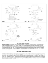
WARNING – RISK OF ELECTRIC SHOCK. INSTALL THIS
TRIM IN RECESSED HOUSINGS THAT HAVE DIMENSIONS
SHOWN IN FIG. 1, WHICH INCLUDE THE FOLLOWING
LUMINAIRES: INCANDESCENT HOUSINGS –
COMMERCIAL ELECTRIC MODELS C7, C7R, C7S, C7SR,
C7IC, C7ICR, C7ICA, C7ICRA, HBR5000SIC; HALO
MODELS H7T, H7RT, H27T, H27RT, H7ICT, H7RICT,
H27ICT, H7ICAT, H7RICAT; CORDELIA LIGHTINGS –
HBR7LICAT, HBR7LICRAT; LITHONIA MODELS – L7X,
L7XR; THOMAS MODELS – PS1, PS1-RM; DMF MODELS-
DH6ICATQ, DH6ICRATQ; NORA MODELS- NHIC -17QAT,
NHRIC-17QAT; ELITE MODELS– B6IC, B6RIC; SEA GULL
MODELS– 11018 AND 121028; HALO LED HOUSINGS –
H750ICAT, H750RICAT.
___________________________
ASSEMBLY AND INSTALLATION
INCANDESCENT HOUSINGS
1.Unscrew the WING NUT inside the CAN to detach the
SOCKET BRACKET from the CAN. Disengage the SOCKET
from the SOCKET BRACKET. (FIG. 2)
2.Thread the SOCKET ADAPTER into the SOCKET. (FIG. 3)
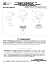
3.Plug the FEMALE CONNECTOR of the RETROFIT TRIM
onto the MALE CONNECTOR of the SOCKET ADAPTER
ASSEMBLY. (FIG. 4)
4.Squeeze both TORSION SPRING arms together and insert
into the TORSION SPRING SLOTS (or RECEIVER
BRACKETS) of the CAN. Tuck all wires into the CAN and
carefully push the RETROFIT TRIM into CAN. (NOTE: To
provide enough room in shallow cans, carefully position
SOCKET ADAPTER and SOCKET adjacent to the long side of
the LED DRIVER prior to inserting the RETROFIT TRIM into
the CAN.) (FIG. 5)
LED HOUSINGS
1.Plug the FEMALE CONNECTOR of the RETROFIT TRIM
onto the MALE CONNECTOR of the HALO HOUSING. (FIG. 4)
2.Squeeze both TORSION SPRING arms together and insert
into the TORSION SPRING SLOTS (or RECEIVER
BRACKETS) of the CAN. Tuck all wires into the CAN and
carefully push the RETROFIT TRIM into CAN. (FIG. 5)
WARNING - RISK OF ELECTRIC SHOCK. DISCONNECT MAIN
POWER AT FUSE OR CIRCUIT BREAKER BEFORE INSTALLING
OR SERVICING THE FIXTURE.
LED 6” RETROFIT TRIM INSTALLATION
INSTRUCTIONS - MODEL CER6731
Please read carefully and save these instructions, as
you may need them at a later date.
QUESTIONS? CALL TOLL
FREE 1-800-345-0542
5 in. – 7 in.
6 in.
FIG. 1
FIG. 2
FIG. 3
PARTS
SOCKET ADAPTER
ASSEMBLY
RETROFIT TRIM
HOUSING DIMENSIONS
FIG. 4
FIG. 5
ALL RIGHTS RESERVED. COPYRIGHT COMMERCIAL ELECTRIC 2010

ALL RIGHTS RESERVED. COPYRIGHT COMMERCIAL ELECTRIC 2010
______________________________
THREE-YEAR LIMITED WARRANTY
Commercial Electric
warrants this product to be free from
defects in material and workmanship for three years from the
original date of purchase by the consumer. This warranty is
limited to the counter replacement at the time of purchase,
with the original purchase receipt. Commercial Electric
will
not be liable for the loss or damage of any kind, incidental or
consequential damages of any kind, whether based on
warranty contract or negligence, and arising in connection
with the sale, use or repair of the product claimed to be
defective. Some states do not allow the exclusion or limitation
of incidental or consequential damages so the above
limitation may not apply to you. This warranty gives you
specific legal rights and you may also have other rights, which
vary from state to state. Misuse, accident, improper
installation or maintenance will also void the warranty.
____________________
DRIVER REPLACEMENT
1. DISCONNECT MAIN POWER AT FUSE OR CIRCUIT
BREAKER.
2. Pull the RETROFIT TRIM down from the RECESSED
HOUSING. Unplug the FEMALE CONNECTOR of the
RETROFIT TRIM from the MALE CONNECTOR of the
SOCKET ADAPTER ASSEMBLY.
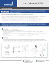
3. Remove the four SCREWS from the CAST HEAT SINK that
is attached to the trim. Lift the CAST HEAT SINK carefully
and remove the plastic lens. (FIG 6)
4. Loosen the SET SCREW that is securing the black wire on
the back of the CAST HEAT SINK. (FIG 6)
5. Remove the DRIVER SCREWS and separate the old LED
driver from the CAST HEAT SINK. (FIG 6)
6. Separate the LED DRIVER CONNECTOR from the
RETROFIT TRIM CONNECTOR. and pull the BLACK
CABLE WIRE through the CAST HEAT SINK. (FIG 7)
7. Connect the LED DRIVER CONNECTOR to the RETROFIT
TRIM CONNECTOR.
8. Re-install the RETROFIT TRIM into the RECESSED
HOUSING.
_______
DIMMING
Although this product is compatible with most common
residential type dimmers, dimming performance depends on
dimmer, dimmer setting (for dimmers with brightness range
adjustments), wiring method, and the number of LED modules.
For best results, set dimmer position at maximum before
adjusting to a lower light level.
Recommended Dimmers (minimum load for four LED modules
maybe required for optimal dimming performance): Leviton
Decora – 6631, IPI06, Lutron Skylark – S-603PGH, and Lutron
Diva – DVWCL-153PDH, CTCL-15PDH, and TGCL-153PH.
MODEL: CDLPS388R15
Class 2 power supply
Dimmable LED Driver
CDL
DC OUTPUT:
24-36V
Regulated current: 400mA
CONFORMS TO UL STD.8750
CERTIFIED TO CSA
STD C22.2 NO.223
RECOGNIZED
COMPONENT
AC INPUT:
120Vac/200mA
60 Hz PF >0.9
L-BLACK
N-WHITE
MADE IN CHINA
Risk of Electric Shock
Dry Location Only
For Indoor Use Only
• Tc
FIG. 7FIG. 6

GENERAL: Todas las conexiones eléctricas deben realizarse
conforme a las normas locales y al Código Eléctrico Nacional (N.E.C.
por sus siglas en inglés). Si no está familiarizado con la instalación
correcta de cableado eléctrico, contrate los servicios de un electricista
certificado.
Retire el adaptador decorativo de la caja y asegúrese de tener todas
las piezas comparándolas con las ilustraciones de las PARTES.
ADVERTENCIA – RIESGO DE DESCARGA ELÉCTRICA. INSTALE
ESTE ADAPTADOR DECORATIVO EN LAS CAJAS DE LUZ
EMPOTRADAS QUE TIENEN LAS DIMENSIONES INDICADAS EN
LA FIG. 1, INCLUYENDO LAS SIGUIENTES LUMINARIAS: CAJAS
INCANDESCENTES – MODELOS C7, C7R, C7S, C7SR, C7IC,
C7ICR, C7ICA, C7ICRA, DE COMMERCIAL ELECTRIC; MODELOS
H7T, H7RT, H27T, H27RT, H7ICT, H7RICT, H27ICT, H7ICAT,
H7RICAT, DE HALO; HBR7LICAT Y HBR7LICRAT DE CORDELIA;
L7X Y L7XR DE LITHONIA; PS1 Y PS1-RM DE THOMAS;
DH6ICATQ Y DH6ICRATQ DE DMF; NHIC -17QAT Y NHRIC-
17QAT DE NORA; B6IC Y B6RIC DE ELITE; 11018 Y 121028 DE
SEA GULL; CAJAS LED DE HALO – H750ICAT Y H750RICAT.
________________________
MONTAJE E INSTALACIÓN
CAJAS INCANDESCENTES
1.Remueva la TUERCA MARIPOSA ubicada dentro del
ALOJAMIENTO DE LA LÁMPARA para soltar la ABRAZADERA DEL
PORTALÁMPARAS. Desconecte el PORTALÁMPARAS de la
ABRAZADERA DEL PORTALÁMPARAS. (FIG. 2)
2.Inserte el ADAPTADOR DEL PORTALÁMPARAS en el
PORTALÁMPARAS. (FIG. 3)
3.Enchufe el CONECTOR HEMBRA del ADAPTADOR
DECORATIVO al CONECTOR MACHO de la UNIDAD DEL
ADAPTADOR DEL PORTALÁMPARAS. (FIG. 4)
4.Apriete los dos brazos del RESORTE DE TORSIÓN para
insertarlos en las RANURAS DEL RESORTE DE TORSIÓN (o
SOPORTES RECEPTORES) del ALOJAMIENTO DE LA LÁMPARA.
Coloque todos los cables en el ALOJAMIENTO DE LA LÁMPARA y
presione con cuidado el ADAPTADOR DECORATIVO en el
ALOJAMIENTO DE LA LÁMPARA. (NOTA: A fin de tener espacio
suficiente en los alojamientos de lámparas poco profundos, coloque
con cuidado el ADAPTADOR DEL PORTALÁMPARAS y el
PORTALÁMPARAS junto al lado más largo del CONTROLADOR DE
LED antes de insertar el ADAPTADOR DECORATIVO en el
ALOJAMIENTO DE LA LÁMPARA.) (FIG. 5)
CAJAS LED
1.Enchufe el CONECTOR HEMBRA del ADAPTADOR
DECORATIVO en el CONECTOR MACHO de la CAJA HALO. (FIG.
4)
2.Apriete los dos brazos del RESORTE DE TORSIÓN para
insertarlos en las RANURAS DEL RESORTE DE TORSIÓN (o
SOPORTES RECEPTORES) del ALOJAMIENTO DE LA LÁMPARA.
Coloque todos los cables en el ALOJAMIENTO DE LA LÁMPARA y
presione con cuidado el ADAPTADOR DECORATIVO en el
ALOJAMIENTO DE LA LÁMPARA. (FIG. 5)
ADVERTENCIA: RIESGO DE DESCARGA ELÉCTRICA. DESCONECTE EL
SUMINISTRO ELÉCTRICO DE LA CAJA DE FUSIBLES O LOS INTERRUPTORES DE
CIRCUITO ANTES DE INSTALAR O DAR MANTENIMIENTO A LA UNIDAD.
INSTRUCCIONES PARA LA INSTALACIÓN DEL
ADAPTADOR DECORATIVO LED DE 6” - MODELO
CER6731
Lea cuidadosamente y guarde estas instrucciones
ya que podría necesitarlas más adelante.
¿PREGUNTAS? LLAME
GRATIS AL 1-800-345-0542
5 in. – 7 in.
6 in.
FIG. 1
FIG. 2
FIG. 3
PARTES
UNIDAD DEL ADAPTADOR
DEL PORTALÁMPARAS
ADAPTADOR DECORATIVO
DIMENSIONES DE LA
CAJA
FIG. 4
FIG. 5
TODOS LOS DERECHOS RESERVADOS. PROPIEDAD INTELECTUAL COMMERCIAL ELECTRIC 2010

TODOS LOS DERECHOS RESERVADOS. PROPIEDAD INTELECTUAL COMMERCIAL ELECTRIC 2010
____________________________
REEMPLAZO DE CONTROLADOR
1. Desconecte la alimentación principal de el fusible o
disyuntor.
2. Baje el adaptador decorativo desde la caja empotrada.
Desenchufe el conector hembra (de la caja empotrada) y el
conector macho (del conjunto del adaptador de enchufe).
3. Quite los cuatro tornillos del disipador de calor que se adjunta al
adaptador decorativo. Levante el disipador de calor
cuidadosamente y quite el lente de plástico. (FIG 6)
4. Afloje el tornillo de ajuste que está asegurando el cable negro en
la parte trasera del disipador de calor. (FIG 6)
5. Quite los tornillos del conductor y separe el controlador de LED
antiguo LED del disipador de calor. (FIG 6)
6. Separe el conector del controlador LED del adaptador decorativo y
jale el cable negro a través del disipador de calor. (FIG 7)
7. Enchufe el conector del controlador LED nuevo con el adaptador
decorativo.
8. Vuelva a instalar el adaptador decorativo en el alojamiento
empotrado.
____________________________________
REGULADOR DE INTENSIDAD DE LA LUZ
Aunque este producto es compatible con la mayoría de los
reguladores (“dimmers”) residenciales más comunes, su rendimiento
depende del regulador, ajuste del regulador (en modelos con ajustes
para escala de luminosidad), método de cableado y número de
módulos LED. Para mejores resultados, coloque el regulador en la
posición máxima antes de ajustarlo a un nivel de luz más bajo.
Reguladores recomendados (podría ser necesaria una carga mínima
para cuatro módulos LED para un rendimiento óptimo): Leviton
Decora – 6631, IPI06, Lutron Skylark – S-603PGH, y Lutron Diva –
DVWCL-153PDH, CTCL-15PDH, y TGCL-153PH.
_________________________________
GARANTÍA LIMITADA POR TRES AÑOS
Commercial Electric
garantiza este producto contra defectos en
sus materiales y mano de obra por un plazo de tres años a partir de
la fecha de compra. Esta garantía está limitada al cambio del
producto en el mostrador al momento de la compra, con la
presentación del recibo de compra original. Commercial Electric
no se responsabiliza por ningún tipo de pérdida o daño así como
tampoco por daños incidentales o indirectos, ya sea que se basen
en el contrato de garantía o en negligencia y que resulten de la
venta, uso o reparación del producto que se reclama como
defectuoso. Algunos estados no permiten la exclusión o limitación
de daños incidentales o indirectos por lo cual la limitación anterior
podría no aplicar a su caso. Esta garantía le otorga derechos
legales específicos y usted podría tener otros derechos que varían
según el estado. El uso indebido, accidente, instalación o
mantenimiento incorrectos invalidarán también la garantía.
MODELO: CDLPS388R15
Controlador LED para Luz Regulable
CDL
SALIDA DE DC:
24-36V
Corriente regulado: 400mA
CONFORME AL ESTÁDAR UL 8750
CERTIFICADO A ESTÁNDAR
CSA C22.2 Nº 223
COMPONENTE
RECONOCIDO
ENTRADA DE AC:
120Vac/200mA
60 Hz PF >0.9
L-NEGRO
N-BLANCO
HECHO IN CHINA
Riesgo de descarga eléctrica
Lugares secos solamente
Para uso interior solamente
Fuente de alimentación clase 2
• Tc
FIG. 7FIG. 6

AVERTISSEMENT – RISQUE DE DÉCHARGE ÉLECTRIQUE.
COUPEZ LE COURANT AU NIVEAU DU DISJONCTEUR OU DE
LA BOÎTE DE FUSIBLES AVANT D’INSTALLER OU
D’EFFECTUER L’ENTRETIEN DU LUMINAIRE.
MODE D’INSTALLATION POUR GARNITURE DE RÉNOVATION
AVEC MODULE DEL DE 15,24 CM - MODÈLES CER6731
Veuillez lire ces instructions attentivement et les
conserver pour pouvoir les consulter au besoin.
GÉNÉRALITÉS : Tous les raccordements doivent être effectués
conformément aux exigences des règlements locaux et du code
national de l’électricité (CNE). Si vous ne connaissez pas les
principes de raccordement d’une installation électrique, veuillez
utiliser les services d’un électricien certifié.
Retirez la garniture de la boîte et assurez-vous qu’il n’y a aucune
pièce manquante en vous référant aux illustrations des PIÈCES.
LE NÉCESSAIRE DE MODERNISATION EST ACCEPTÉ EN TANT
QUE COMPOSANT D’UN LUMINAIRE LED, SOUS RÉSERVE
D’APPROBATION DE L’ENSEMBLE PAR LA CSA OU PAR LES
POUVOIRS DE RÉGLEMENTATION.
AVERTISSEMENT – RISQUE DE DÉCHARGE ÉLECTRIQUE.
INSTALLEZ CETTE GARNITURE DANS UN BOÎTIER DONT LES
DIMENSIONS CORRESPONDENT À CELLES INDIQUÉES À LA
FIGURE 1. LES MODÈLES SUIVANTS CONVIENNENT
NOTAMMENT À CETTE GARNITURE: NICHES POUR LAMPE À
INCANDESCENCE - COMMERCIAL ELECTRIC C7, C7R, C7S,
C7SR, C7IC, C7ICR, C7ICA, C7ICRA; MODELOS H7T, H7RT,
H27T, H27RT, H7ICT, H7RICT, H27ICT, H7ICAT, H7RICAT, DE
HALO; HBR7LICAT ET HBR7LICRAT DE CORDELIA; L7X ET
L7XR DE LITHONIA; PS1 ET PS1-RM DE THOMAS; DH6ICATQ ET
DH6ICRATQ DE DMF; NHIC -17QAT ET NHRIC-17QAT DE NORA;
B6IC ET B6RIC DE ELITE; 11018 ET 121028 DE SEA GULL; HALO
H7T, H7RT, H27T, H27RT, H7ICT, H7RICT, H27ICT, H7ICAT,
H7RICAT; NICHES HALO DEL - H750ICAT ET H750RICAT.
_____________________________
ASSEMBLAGE ET INSTALLATION
NICHES POUR LAMPE À INCANDESCENCE
1.Dévissez l’ÉCROU À OREILLES situé à l’intérieur du BOÎTIER pour
détacher le SUPPORT DE LA DOUILLE. Dégagez la DOUILLE du
SUPPORT. (FIG. 2)
2.Vissez le SUPPORT ADAPTATEUR dans la DOUILLE. (FIG. 3)
3.Branchez le CONNECTEUR FEMELLE de la GARNITURE DE
RÉNOVATION dans le CONNECTEUR MÂLE du SUPPORT
ADAPTATEUR. (FIG. 4)
4.Serrez les deux pattes à RESSORTS DE TORSION l’une contre
l’autre et insérez-les dans les FENTES DE RESSORT DE TORSION
(ou SUPPORTS DE RÉCEPTION) du BOÎTIER. Rentrez tous les fils
dans le BOÎTIER et poussez doucement la GARNITURE DE
RÉNOVATION dans le BOÎTIER. (À NOTER : dans le cas de boîtiers
peu profonds, placez soigneusement le SUPPORT ADAPTATEUR et
la DOUILLE contre le côté le plus long du TRANSFORMATEUR DEL
avant d’insérer la GARNITURE DE RÉNOVATION dans le BOÎTIER.)
(FIG. 5)
NICHES POUR DEL
1.Branchez le CONNECTEUR FEMELLE de la GARNITURE DE
RÉNOVATION dans le CONNECTEUR MÂLE du BOÎTIER HALO.
(FIG. 4)
2.Serrez les deux pattes à RESSORTS DE TORSION l’une contre
l’autre et insérez-les dans les FENTES DE RESSORT DE TORSION
(ou SUPPORTS DE RÉCEPTION) du BOÎTIER. Rentrez tous les fils
dans le BOÎTIER et poussez doucement la GARNITURE DE
RÉNOVATION dans le BOÎTIER. (FIG. 5)
DES QUESTIONS? APPELEZ SANS
FRAIS AU 1-800-345-0542
12,7 – 17,78 cm
15,24 cm
FIG. 1
FIG. 2
FIG. 3
PIÈCES
SUPPORT ADAPTATEUR
GARNITURE DE
RÉNOVATION
DIMENSIONS DU BOÎTIER
FIG. 4
FIG. 5
TOUS DROITS RÉSERVÉS COMMERCIAL ELECTRIC 2010

TOUS DROITS RÉSERVÉS COMMERCIAL ELECTRIC 2010
_______________________________
GARANTIE LIMITÉE DE TROIS ANS
Commercial Electric
garantit ce produit contre tout défaut de
matériaux ou de fabrication pour une période d’un an à partir de la
date d’achat initial par le client, à l’exception de la pile. La garantie
se limite à la correction desdits défauts en remplaçant le produit
défectueux, accompagné de la preuve d’achat originale. Cette
garantie ne couvre pas les ampoules. Commercial Electric
ne
pourra être tenue responsable d’aucune perte ou dommage de
quelque sorte que ce soit, d’aucun dommage accessoire ou indirect,
fondé sur la garantie ou la négligence, découlant de la vente, de
l’utilisation ou de la réparation du produit réputé défectueux.
Certains États interdisent l’exclusion ou la limitation des dommages
accessoires ou indirects et, par conséquent, cette garantie peut ne
pas s’appliquer à vous. Cette garantie vous confère des droits
spécifiques, en sus des autres droits dont vous pourriez bénéficier et
qui peuvent varier d’un État à l’autre. Une utilisation incorrecte, un
accident, une installation inadéquate ou un entretien déficient aura
pour effet d’annuler la présente garantie.
_______________________________
REMPLACEMENT DE CONTRÔLEUR
1. Débranchez l'alimentation principale du fusible ou
disjoncteur.
2. Baissier le GARNITURE DE RÉNOVATION de la BOÎTIER.
Débranchez le CONNECTEUR FEMELLE de la GARNITURE
DE RÉNOVATION du CONNECTEUR MÂLE du SUPPORT
ADAPTATEUR.
3. Retirez les quatre vis du dissipateur thermique qui est attaché à
la garniture. Soulevez le dissipateur avec précaution et retirer la
lentille en plastique. (FIG 6)
4. Desserrer la vis qui appose le fil noir sur le dos du dissipateur
thermique. (FIG 6)
5. Retirez les vis du pilote et séparer l'ancien pilote de LED du
dissipateur thermique. (FIG 6)
6. Séparer le connecteur du pilote de la garniture de rénovation et
retirez sur le fil noir à travers le dissipateur de chaleur pour
déconnecter la connexion rapidement et soigneusement
réinsérer le nouveau câble. (FIG 7)
7. Branchez le connecteur du pilote à garniture de rénovation.
8. Réinstaller le garniture de rénovation dans le boîtier à
encastrer.
____________________________________
GRADATION DE L’INTENSITÉ LUMINEUSE
Bien que ce produit convienne à la plupart des gradateurs
résidentiels courants, la gradation de l’intensité lumineuse dépend
du gradateur lui-même, de ses réglages (dans le cas de gradateurs
comportant une programmation des intensités lumineuses), du type
de filage électrique et du nombre de modules DEL. Pour obtenir de
meilleurs résultats, ouvrez le gradateur à la plus forte intensité
lumineuse avant de diminuer le niveau d’éclairage.
Gradateurs recommandés (la charge minimale pour quatre modules
DEL peut être nécessaire pour assurer un meilleur contrôle du
niveau d’éclairage) : Leviton Decora – 6631, IPI06, Lutron Skylark –
S-603PGH et Lutron Diva – DVWCL-153PDH, CTCL-15PDH, et
TGCL-153PH.
MODEL: CDLPS388R15
Alimentation électrique de classe 2
Circuit de commande DEL ajustable
CDL
SORTIE CC:
24-36V
Courant régulé: 400mA
CONFORME Á LA NORME UL 8750
CERTIFIÉ SELON LA NORME
CSA C22.2 Nº 223
COMPOSANT
RECONNU
ENTRÉE AC:
120Vac/200mA
60 Hz PF >0.9
L-NOIR
N-BLANC
MADE IN CHINA
RISQUE DE CHOC ÉLECTRIQUE ENDROITS
ENDROITS SECS SEULEMENT
POUR UTILISATION A L’
INTERIEUR SEULEMENT
• Tc
FIG. 7FIG. 6
/