Page is loading ...

ASSEMBLY INSTRUCTIONS FOR OL2207 (E) REV 10/27/04
IMPORTANT
TURN OFF POWER AT MAIN FUSE TO CIRCUIT
BREAKER BOX BEFORE STARTING INSTALLATION
1.
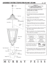
Carefully unpack and identify all parts before beginning
assembly. Bulb not included.
2.
Remove finial by turning counter-clockwise. Then lift
top cover with knob.
3. Install light bulb (not included). See relamping label at
socket area for type and maximum allowed wattage.
4. Install top cover. Secure with finial.
5.
Electrical installation onto post: If you are replacing and
existing fixture, disconnect and remove the old fixture.
A)
Slip lantern base over post. Mark position of holes
in post cup on post.
B)
Remove lantern base and expose the supply wiring
from above post. Drill 1/8" diameter pilot holes in
post at places where marked.
C)
Make wire connections. (wire connectors not
provided). Refer to chart below for correct
c
onnections. Conne
c
t fixture wir
e
s
to
supply wires
a
ccordingly.
D) Connect ground wire from supply source to fixture
ground wire with connector. Never connect ground
wire to black or white power supply wires. Carefully
place wires inside post.
E) Slip post cup onto post (not supplied). Align holes in
post cup with holes in post. Secure them together by
fastening with provided sheet metal screws.
Tracer Wire
*Note: When parallel wire (SPT 1 & SPT2)
is used. One wire is square shaped or
ridged and the other wire will be round
in shape or smooth. (See Illustration)
Connect Black Fixture Wire to:
Black Supply Wire or
*Parallel cord
(round & smooth)
Clear, Brown, Gold or Black
without tracer
Insulated wire
(other than green)
with copper conductor
Connect White Fixture Wire to:
White Supply Wire or
*Parallel cord
(square & ridged)
Clear, Brown, Gold or Black
with tracer
Insulated wire
(other than green)
with silver conductor
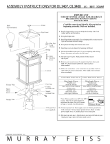
Top Cover
Center Pipe
Finial
Knob
Bulb
(Not
Included)
Main Frame
Post Cup
Post
(Not Included)
Sheet Metal
Screw
Fixture
Ground Wire
Supply
Ground Wire
Fixture
Wires
Supply
Wires
MUR R AY FEI SS
©M URRAY FEI SS I M PORT LLC.
/
