RAB Lighting EZPAN2X4-40N/D10/LC/E2 Operating instructions
- Type
- Operating instructions

RAB Lighting is committed to creating high-quality, aordable, well-designed and energy-ecient LED lighting and controls that make it easy for electricians to install
and end users to save energy. We’d love to hear your comments. Please call the Marketing Department at 888-RAB-1000 or email: [email protected]
INSTRUCTIONS
EZPAN® & EZPAN®HE w/ BATTERY BACKUP
IMPORTANT
READ CAREFULLY BEFORE INSTALLING FIXTURE. RETAIN THESE INSTRUCTIONS FOR FUTURE REFERENCE.
RAB xtures must be wired in accordance with the National Electrical Code and all applicable local codes. Proper grounding is
required for safety. THIS PRODUCT MUST BE INSTALLED IN ACCORDANCE WITH THE APPLICABLE INSTALLATION CODE BY A PERSON
FAMILIAR WITH THE CONSTRUCTION AND OPERATION OF THE PRODUCT AND THE HAZARDS INVOLVED.
WARNING: Make certain power is OFF before installing or maintaining xture. No user serviceable parts inside.
CAUTION: For proper weatherproof function all gaskets must be seated properly and all screws inserted and tightened
SAFETY INSTRUCTIONS
WARNING: Risk of re or electric shock. Suitable for Damp locations.
WARNING: Suitable for 9/16” or 15/16” Flat Tee Grid in both Insulated Ceilings and Non-Insulated Ceilings. Access above ceiling required.
WARNING: Do not handle energized xture when hands are wet, when standing on wet or damp surfaces, or in water.
WARNING: Vapor barrier must be suitable for 90° C.
WARNING: Fixture to be independently supported to building structure.
RECESSED CEILING MOUNTING
The xture is suitable only for INDOOR RECESSED CEILING
application. Above ceiling access required.
To mount in an insulated or non-insulated ceiling - 9/16” or 15/16”
exposed Flat Tee Grid Ceiling follow the steps below.
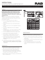
1. Firmly bend the pre-installed Grid Clips (up and out as shown
in Fig. 1. )
2. Rotate and slide the Fixture as required to t through the Tee-
Grid Bar and place it as indicated by the directional arrow as
shown in Fig. 2. Secure the Fixture to the Tee-Grid Bar.
3. Support wires are required by Installation Codes. Support the
Fixture to the building structure by Support Wires (supplied
by others) through the Grid Clip Hole.
4. Make sure that the orientation of the Splice Box and Access
Plate faces an accessible tile to make electrical splices.
5. Loosen Access Plate Screw and remove the Access Plate.
Knock out appropriate Conduit Knockouts on the Access
Plate to route input conduit. Use appropriate conduit
connectors as required by code (Fig. 3).
6. Connect wires as shown in wiring diagram. Push all wires
back into the Splice Box. Use appropriate UL approved wire
connectors as required by code to complete wiring. Be careful
not to pinch wires. WARNING: To prevent wiring damage or
abrasion, do not expose wiring to edges of sheet metal or
other sharp objects.
7. Install the Switch Plate (along with the charging indicator) in a
suitable Junction Box (by others) in an adjacent ceiling tile. It
should be located nominal 2 feet from the xture.
8. Replace Access Plate and tighten Access Plate Screw.
Fig: 1
Fig: 2
Fig: 3
Fixture
Firmly bend Grid
Clips up and out
Splice Box Access Plate Screw
Junction Box
(by others)
Conduit Knockouts Switch Plate
Tee-Grid Bar
Fixture
Grid Clip
Access Plate

RAB Lighting is committed to creating high-quality, aordable, well-designed and energy-ecient LED lighting and controls that make it easy for electricians to install
and end users to save energy. We’d love to hear your comments. Please call the Marketing Department at 888-RAB-1000 or email: [email protected]
INSTRUCTIONS
EZPAN® & EZPAN®HE w/ BATTERY BACKUP
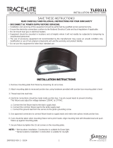
WIRING
OPERATION
CAUTION: THIS IS A BATTERY BACKUP FIXTURE for standby
lighting. Voltage could be present in Battery. To prevent
high voltage from being present on output leads, inverter
connector must be open. Do not join inverter connector
until installation is complete and AC power is supplied to the
emergency ballast.
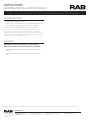
Note: Make sure that the necessary branch circuit wiring is
available. An unswitched AC source of power is required. The
emergency ballast must be fed from the same branch circuit as
the AC ballast (see Fig. 4).
Do not use any supply voltage other than 120V-277V.
1. Connect the UNSWITCHED black xture lead to the HOT
supply lead.
2. If using an unswitched circuit, connect both black leads
together.
3. If using a switched circuit, connect SWITCHED black lead to
the switch.
4. Connect the COMMON xture lead to the COMMON
supply lead.
5. For 0-10V Dimming, connect DIM (+) purple lead and DIM (-)
gray lead to 0-10V dimmer connections on the driver.
6. Connect the GROUND wire from xture to supply ground.
7. All unused leads must be capped and insulated.
8. After installation is complete, supply AC power to the
emergency ballast and join the inverter connector.
9. At this point, power should be connected to both the AC
ballast and the emergency ballast, the Charging Indicator
Light should illuminate indicating the battery
is charging.
10. A short duration discharge test may be conducted after the
emergency ballast has been charging for one hour. Charge for
24 hours before conducting a 90 minute discharge test. Refer
to OPERATION.
1. When AC power is applied, the charging indicator light is
illuminated, indicating that the battery is being charged.
2. When power fails, the emergency driver automatically
switches to emergency power (internal battery), operating at
reduced output. The emergency driver supplies 12W of power
in emergency mode for a minimum of 90 minutes.
3. When AC power is restored, the emergency driver automatically
returns to charging mode.
BATTERY
CONNECTOR:
CONNECT
ONLY AFTER
AC SUPPLY
POWER IS
CONNECTED
LIGHT
FIXTURE
BACKUP
DRIVER
INSIDE FIXTURE
BATTERY
FIG. #4
LED
DRIVER
LINE
COMMON
(+) DIM V+
(-) DIM V-
GROUND
L
N
DIM -
DIM +
LED +
LED -
CHARGING
INDICATOR LIGHT /
TEST SWITCH
Black/Unswitched Line 120-277V
Disconnect Factory installed
wires connected to LED Board.
Connect Emergency Battery
pack wires accordingly.
IF UNSWITCHED,
CAP TWO BLACK
WIRES TOGETHER
Black/Switched Line 120-277V
White Common 120-277V
LEAVE OPEN
DO NOT CONNECT
DURING
MANUFACTURING
INVERTER
CONNECTOR:
CONNECT
ONLY AFTER
AC SUPPLY
POWER IS
CONNECTED
MAINTENANCE
Although no routine maintenance is required to keep the
emergency driver functional, it should be checked periodically to
ensure that it is working. The following schedule is recommended:
1. Visually inspect the charging indicator light monthly. It should
be illuminated.
2. Test the emergency operation of the xture at 30-day intervals
for a minimum of 30 seconds.
3. Conduct a 90-minute discharge test once a year. Fixture
would provide reduced illumination for a minimum of 90
minutes.

RAB Lighting is committed to creating high-quality, aordable, well-designed and energy-ecient LED lighting and controls that make it easy for electricians to install
and end users to save energy. We’d love to hear your comments. Please call the Marketing Department at 888-RAB-1000 or email: [email protected]
INSTRUCTIONS
EZPAN® & EZPAN®HE w/ BATTERY BACKUP
EZPAN & EZPANHE
1X4, 2X2, 2X4 - w/ EM 0220
73535-RAB
Easy Answers
rablighting.com
Visit our website for product info
Tech Help Line
Call our experts: 888 722-1000
e-mail
Answered promptly - [email protected]
Free Lighting Layouts
Answered online or by request
© 2020 RAB LIGHTING Inc.
Northvale, New Jersey 07647 USA
RAB WARRANTY: RAB’S warranty is subject to all terms and conditions found at rablighting.com/warranty.
TROUBLESHOOTING
To reduce the risk of electric shock, disconnect both normal and emergency power
supplies and converter connector of the emergency ballast before servicing. Do not
attempt to service the emergency ballast. The use of accessory equipment may cause an
unsafe condition. Do not use this product for other than intended use. Refer any servicing
indicated by these checks to aqualified service personnel.
1. Is the xture grounded properly?
2. If the charging indicator light does not illuminate after pressing
the test button, check if battery is connected properly.
3. Is the battery backup dip switch position set correctly?
CLEANING
CAUTION: Be sure xture temperature is cool enough to
touch. Do not clean or maintain while xture is energized.
1. Clean polystyrene lens & xture with non-abrasive cleaning
solution.
2. Do not open xture to clean the LEDs. Do not touch the
LEDs.
Note: These instructions do not cover all details or variations in equipment nor do they provide for every possible situation during installation, operation or maintenance.
-
 1
1
-
 2
2
-
 3
3


RAB Lighting EZPAN2X4-40N/D10/LC/E2 Operating instructions
- Type
- Operating instructions
Ask a question and I''ll find the answer in the document
Finding information in a document is now easier with AI
Related papers
-
RAB Lighting EZPANFA2X4/D10 Operating instructions
-
-
-
-
RAB Lighting EZPANHE2X2-12YN/D10 Operating instructions
-
-
RAB Lighting EZPAN2X4-30/D10 Operating instructions
-
RAB Lighting WP3LED93L-730U/PCS2 Operating instructions
-
-
Other documents
-
 BARRON TLED804 Series Die-cast Globe Vaportight Installation guide
-
RAB SMKEZPAN1X4 User manual
-
 BARRON TLED111P Series Half Round Wall Sconce Installation guide
-
RAB HID-65-E26-8XX-BYP-GL Operating instructions
-
-
-
-
Chloride ZIS25W Install Instructions
-
RAB HAZSHARK2 Operating instructions
-
RAB SWISH34 2×2 Watt Economy Center Basket LED Troffer Installation guide

