Advent ADVGEN45A4PW4 User manual

Type
User manual

The Advent ADVGEN45A4PW4 auto-dimming mirror seamlessly blends style and functionality to enhance your driving experience. Its auto-dimming feature automatically adjusts the mirror's tint to reduce glare from headlights, improving nighttime visibility and driving safety. Additionally, the mirror's built-in HomeLink system allows you to conveniently control and operate garage doors, gate operators, and other compatible devices with the touch of a button.

The Advent ADVGEN45A4PW4 auto-dimming mirror seamlessly blends style and functionality to enhance your driving experience. Its auto-dimming feature automatically adjusts the mirror's tint to reduce glare from headlights, improving nighttime visibility and driving safety. Additionally, the mirror's built-in HomeLink system allows you to conveniently control and operate garage doors, gate operators, and other compatible devices with the touch of a button.

Page 1 of 10 Revision A 550-0427
Bezelled
ADVGEN45A4
Bezelled w/ Homelink
ADVGEN80EXP
ADVGEN45A4PW4
ADVGEN40A4
Frameless
ADVGEN8EXP
Frameless w/ Homelink
ADVGEN85EXP
ADVGEN45AB5
TOOLS REQUIRED:
Safety Glasses
Utility Knife
Pliers
#2 Phillip's Screwdriver
Clean Rag
Electrical Tape
4mm Flat Screwdriver
Flashlight
DC Voltmeter
Fish-Wire (Coat Hanger)
#T20 Torx Driver
Panel Removal Tool
Gentex by VOXX Corporation
Installation Instructions
ADVGEN45A4PW4
ADVGEN40A4
ADVGEN45AB5
ADVGEN45A4
ADVGENFL85EXP
ADVGENFL80EXP
Page 2 of 10 Revision A 550-0427
Perform the following pre-installation steps:
1. Place kit components on a clean, padded surface.
2. Record your programmed radio stations.
3. Remove driver side scuff plate. (Fig. 1)
4. Remove driver side door seal. (Fig. 2)
5. Remove driver side kick plate / cowl cover. (Fig. 3)
6. Remove driver side grab handle if equipped. (Fig. 4)
7. Remove driver side A-pillar trim. (Fig. 5)
INSTALLATION PRECAUTIONS / NOTES:
Do not use excessive force when removing OEM mirror from windshield.
Do not push fish-wire too far into dash to avoid damage to existing components.
Do not place wire harness against objects with sharp edges that may cause electrical shorting.
On vehicles equipped with A-pillar (side impact or SRS) airbags, verify mirror harness path remains
clear of airbag. Harness should follow and be secured to, existing OEM wiring with tie wraps.
Verify that auto-dimming mirror harnesses do not interfere with brake, clutch, emergency brake or air
bag
operation. Use tie wraps to bundle and secure wiring away from critical locations.
Preparation
1
2
3
4
5
Page 3 of 10 Revision A 550-0427
8. Remove OEM mirror. (Fig. 6,7 or 8)
a) Loosen #T20 torx screw on mirror mount and slide mirror
upwards off from windshield button. (Fig. 6)
- - OR - -
b) Insert 4mm into opening at bottom of mirror mount to disengage
locking tab and slide mirror upwards off from windshield button.
(Fig. 7)
NOTE: Gently wiggling mirror while sliding upwards will assist
removal.
- - OR - -
c) Insert panel removal tool into opening at bottom of mirror mount
to disengage locking tab and slide mirror upwards off from
windshield button.
(Fig. 8)
NOTE: Gently wiggling mirror while sliding upwards will assist
removal.
1. Attach auto-dimming mirror.
a) Hold the mirror and slide the mirror downwards over wind-shield
button until fully seated. (Fig. 9)
b) Using #T20 torx driver, tighten the mirror mounting bracket
screw to 1.3 ft-lbs (17.8 kg-cm). DO NOT OVERTIGHTEN
NOTE: You will need to find a supply wire in your vehicle that provides
+12V when vehicle is running or the key is in the ON or ACC
position. You will also need to find a supply wire that provides
+12V constant power when vehicle is both ON and OFF. Your
automotive repair shop may sometimes be able to advise readily
available locations for connecting to these power sources.
A TIP: The cigarette lighter or power port receptacle may be a source of
switched +12V or constant +12V, depending on vehicle make.
1. Locate ignition (+12V switched) wire.
a) Using a multi-meter, find a wire exiting the fuse block or junction
block that tests +12V and is controlled by the ignition switch.
Operate vehicle accessories (power windows, door locks, power
mirrors, etc.) to ensure that voltage does not drop on this wire.
(Fig. 10)
b) Ensure power in this wire is off when vehicle key is OFF and
label wire "IGNITION."
Auto-Dimming Mirror Installation
CAUTION
!
Do not use excessive force. Damage to windshield could occur.
Route Auto-Dimming Mirror Harness to Vehicle Power
1.3 ft-lbs
CAUTION
!
6
8
9
10
7
CAUTION
!
Page 4 of 10 Revision A 550-0427
2. Locate constant power (+12V constant) wire.
a) Using a multi-meter, find a wire exiting the fuse block that tests
+12V with vehicle ignition in the ACC, ON and OFF positions.
(Fig. 11)
b) Ensure power in this wire is still present when vehicle key is
OFF and label wire "CONSTANT."
3. Disconnect vehicle's negative battery terminal. (Fig. 12)
4. Plug auto-dimming mirror harness into back of mirror. (Fig. 13)
5. Route harness up to vehicle headliner. (Fig. 14)
a) Install optional wire cover (if purchased). (Fig. 15)
6. Route haress across vehicle headliner to top of A-pillar on side of
vehicle where vehicle connection wires / fuse block were found.
a) Use panel removal tool to ensure harness is tucked between
headliner and roof of vehicle. (Fig. 16)
11
12
13
14
15
16
Page 5 of 10 Revision A 550-0427
7. Route harness down A-pillar. (Fig. 17)
NOTE: Harness will be secured later in installation procedure.
8. Route harness to vehicle connection wires.
a) Using fish-wire, route harness from base of A-pillar through dash
and into connection wire / fuse block area. (Fig. 18)
9. Attach wire tap to vehicle wire marked IGNITION.
a) Center blade of wire tap on IGNITION wire and close wire tap
with pliers. (Fig. 19)
b) Ensure both halves of wire tap are closed completely and
locking tab is engaged.
10. Connect auto-dimming mirror harness switched power wire to
vehicle wire marked IGNITION.
a) Locate the harness wire with WHITE STRIPE.
b) Insert spade terminal on WHITE STRIPE wire into the wire tap
on the vehicle wire labeled IGNITION. (Fig. 20)
11. Attach wire tap to vehicle wire marked CONSTANT.
a) Center blade of wire tap on CONSTANT wire and close wire tap
with pliers. (Fig. 21)
b) Ensure both halves of wire tap are closed completely and
locking tab is engaged.
12. Connect auto-dimming mirror harness constant power wire to
vehicle wire marked CONSTANT.
a) Locate the SOLID BLACK harness wire with spade terminal.
b) Insert spade terminal on SOLID BLACK wire into the wire tap
on the vehicle wire labeled CONSTANT. (Fig. 22)
19
22
21
20
18
17
Page 6 of 10 Revision A 550-0427
13. Connect auto-dimming mirror harness ground wire.
a) Locate a ground bolt near connection / fuse block area and
remove.
NOTE: Bolt locations may vary but common locations are in the
kick plate / cowl cover area or parking brake release
handle.
b) Install ring terminal of harness over bolt and reinstall. (Fig. 23)
1. Reconnect negative battery cable.
2. Turn the ignition switch ON/ACC position.
3. With the vehicle in a fairly well-lit area, perform the following:
a) To make sure the auto-dimming feature is on, verify that the
green LED to the left of the center switch is on. If it is not on,
push the switch to turn the green LED on.
b) Cover the forward looking photocell on the back of mirror with a
dark cloth or towel. (Fig. 24)
In a few seconds, the mirror will begin to darken.
NOTE: Time to darken will vary with ambient light level.
c) Remove the cover from the forward looking photo cell and the
mirror will begin to clear.
d) Verify that either a direction, such as NE, or “CAL” is displayed
in the display window. If not, ensure the feature is turned ON
by pressing the button.
4. Turn the ignition key to the OFF position.
5. Push each HomeLink® button (if equipped), one at a time, and
verify that LED indicator to the left of the center switch illuminates
with a red LED. (Fig. 25)
6. If mirror is equipped with maplights, push each maplight button
to ensure lights are operational. (Fig. 26)
7. Testing is now complete.
23
Testing.
Red LED
HomeLink Buttons
24
26
25
Maplight Buttons
Page 7 of 10 Revision A 550-0427
1. Adjust compass zone after EC mirror installation.
a) The zone setting is factory preset to Zone 8. Refer to Compass
Calibration Zone Map to find correct compass zone
setting for your geographical location. (Fig. 27)
b) To change the zone setting, push and hold the button until
a number appears in the display. Press button repeatedly until
desired compass zone number is reached.
1. Calibrate compass.
a) Drive to an open, level area, away from large metallic objects or
structures.
b) Hold the button for approximately 9 seconds until “CAL”
or "C" text appears in the display. Release the button to
enter the calibration mode.
c) Drive slowly in up to 3 circles until the “CAL” or "C" text
disappears, and a directional heading is displayed.
The compass is now calibrated.
Compass Zone Adjustment
1
2
3
4
5
6
7
8
9
10
11
12
13
14
15
2
3
4
5
6
7
8
9
10
11
12
13
14
Compass Calibration
27
Page 8 of 10 Revision A 550-0427
To Operate the HomeLink® Feature:
Please refer to the programming instructions outlined in this manual or:
a) Visit the HomeLink® website at www.homelink.com
b) Call the HomeLink® customer support line at 1-800-355-3515
WARNING! Before programming HomeLink® to a garage door opener or gate
operator, make sure that people and objects are out of the way of the device to
prevent potential harm or damage. When programming a garage door opener, it is
advised to park outside of the garage. Do not use HomeLink® with any garage door
opener that lacks safety stop and reverse features as required by U.S. federal
safety standards (this includes any garage door opener model manufactured before
April 1, 1982). A garage door that cannot detect an object signaling the door to
stop and reverse does not meet current U.S. federal safety standards. For more
information, contact HomeLink® at www.homelink.com or by calling 1-800-355-
3515.
1. To begin, press and hold the 2 outer HomeLink® buttons (to clear
memory) until the indicator light (LED) blinks slowly (approximately 20
seconds). (Fig. 28)
2. Release both buttons.
NOTE: Do not hold the buttons for longer than 30 seconds. Do not
repeat this step when programming additional devices to
remaining buttons.
3. Position the end of the hand-held transmitter 1-3 inches away from the
HomeLink® button you wish to program while keeping the indicator light
in view.
4. Simultaneously press and hold both the chosen HomeLink® and hand-
held transmitter buttons. (Fig. 29)
Do not release the buttons until step 5 has been completed.
HomeLink® Feature and Programming Instructions
Press and Hold for 20s seconds…
LED blinks slowly…
Release buttons
Press and hold both…
LED blinks fast…
Release both buttons
29
28
Page 9 of 10 Revision A 550-0427
NOTE: Some gate operator and garage door openers may require you to
replace this Programming step 4 with procedures noted in the
“Gate Operator / Canadian Programming” section.
5. After the HomeLink® indicator light changes from a slow to a rapidly
blinking light, release both the HomeLink® and hand-held transmitter
buttons.
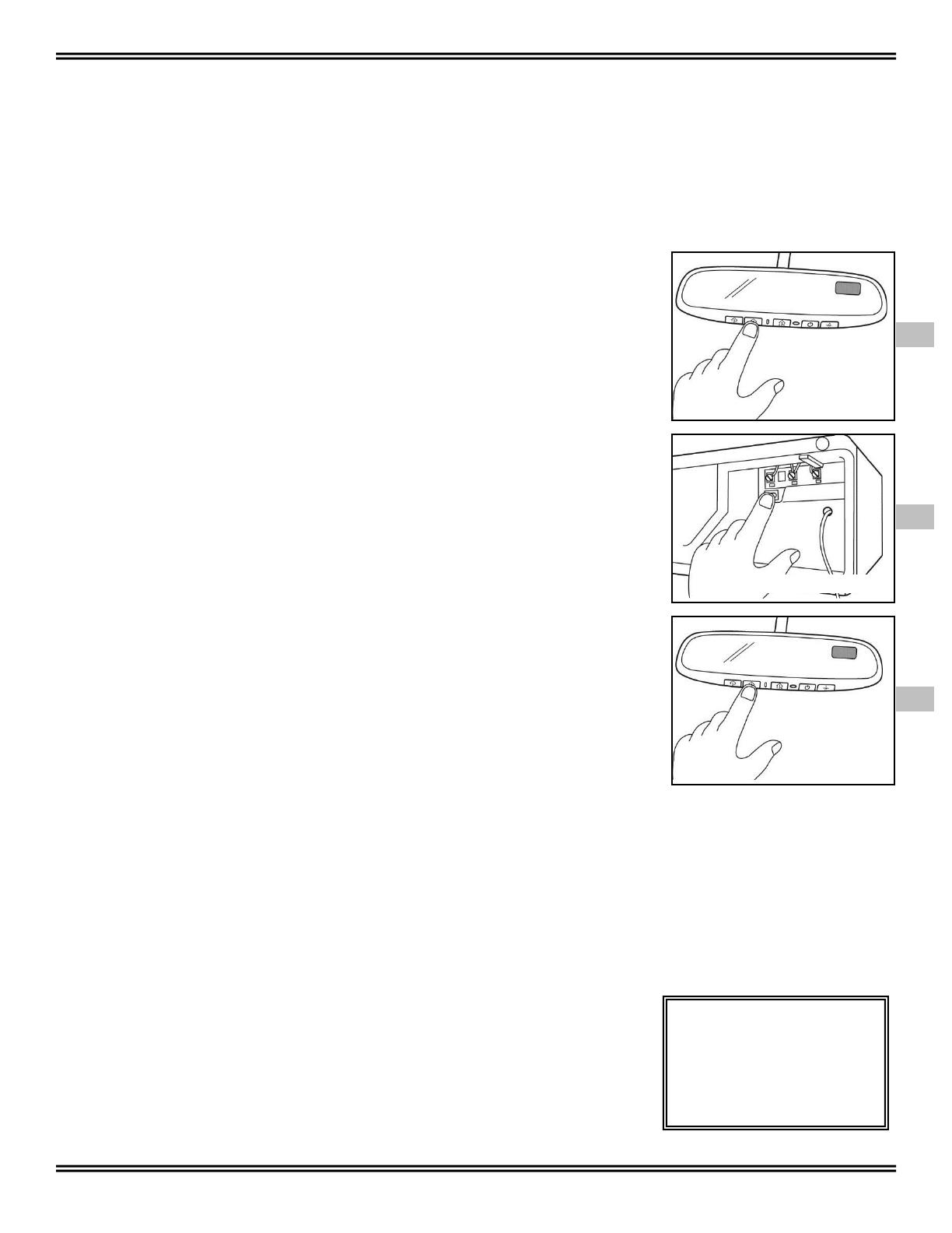
6. Press and hold the just-trained HomeLink® button and observe the
indicator light.
If the indicator light blinks rapidly for 2 seconds and then turns to a
constant light, the device being programmed utilizes rolling code and
programming is not complete until the following steps are completed.
(Fig. 30)
7. On the garage door opener receiver (motor-head unit) locate the “learn”
or “smart” button. This can usually be found where the hanging antenna
wire is attached to the motor- head unit.
8. Firmly press and release the “learn” or “smart” button. (Fig. 31)
NOTE: You have 30 seconds to initiate step 9.
9. Return to the vehicle and firmly press, hold for 2 seconds and release
the programmed HomeLink® button. (Fig. 32)
10. Repeat the “press/hold/release” above a second time and possibly a
third time (depending on brand of device).
HomeLink® should now activate your rolling code equipped device.
Gate Operator / Canadian Programming:
Canadian radio-frequency laws require transmitter signals to “time-out” or quit after
several seconds of transmission which may not be long enough for HomeLink® to
pick up the signal during programming. Similar to this Canadian law, some U.S.
gate operators are designed to “time-out” in the same manner.
If you live in Canada or you are having difficulties programming a gate operator by
using the “Programming” procedures (regardless of where you live), replace
“Programming HomeLink® step 4 with the following:
NOTE: If programming a garage door opener or gate operator, it is advised to
unplug the device during the “cycling” process to prevent possible overheating.
4. Continue to press and hold the HomeLink button while you press and
release - every 2 seconds (“cycle”) your hand-held transmitter until the
frequency signal has successfully been accepted by HomeLink. (The
indicator light will flash slowly and then rapidly.)
Proceed with “Programming” step 5 to complete.
Erasing All Programmed HomeLink Buttons:
Press and hold the two outer HomeLink buttons (as shown in Fig. 1), releasing only
when the HomeLink indicator light begins to flash after 20 seconds. Do not hold for
longer than 30 seconds.
For all other questions, please
contact VOXX Corporation at
1-800-371-7725
Hold for 2 seconds and
release
Press button…
Fast blink for 2
seconds then constant
= rolling code…
Continue programming
instructions
Press “Learn” button…
30 SECONDS TO GET TO VEHICLE
31
32
30
Page 10 of 10 Revision A 550-0427
TROUBLESHOOTING
PROBLEM
SOLUTION
1
"C" or "CAL" is displayed in display window
Perform calibration sequence (ref. Sec. 8)
2 Inaccurate compass direction
Perform compass zone setting procedure
(ref. Sec. 7)
Vehicle magnetics may have changed. Perform
calibration sequence (ref. Sec. 8)
NOTE: Installing items such as a ski rack,
antenna, luggage rack or recent body
repair can cause changes to the vehicle's
magnetic field.
3 Mirror does not dim
Ensure connector is plugged into back of mirror.
Ensure harness wires are connected to vehicle
wires.
Ensure nothing is blocking sensor on front of mirror
or its viewing path to the rear window of vehicle.
4 Mirror dims constantly
Ensure nothing is blocking forward-looking sensor
on back of mirror.
5
Cannot program garage door opener or
other remote control device
Contact HomeLink® at 1-800-355-3515 or visit
www.homelink.com for more information.
6 Display window shows "SC" (short circuit)
Indicates Short Circuit. Check all power wires to
mirror for breaks, crimps or slices. Repair wires
with electrical tape.
For customer or technical support please call VOXX support:
1-800-300-4550
9am – 9pm (Eastern) Mon – Friday
10am 2pm (Eastern) Sat
  • Page 1 1
  • Page 2 2
  • Page 3 3
  • Page 4 4
  • Page 5 5
  • Page 6 6
  • Page 7 7
  • Page 8 8
  • Page 9 9
  • Page 10 10

Advent ADVGEN45A4PW4 User manual

Type
User manual

The Advent ADVGEN45A4PW4 auto-dimming mirror seamlessly blends style and functionality to enhance your driving experience. Its auto-dimming feature automatically adjusts the mirror's tint to reduce glare from headlights, improving nighttime visibility and driving safety. Additionally, the mirror's built-in HomeLink system allows you to conveniently control and operate garage doors, gate operators, and other compatible devices with the touch of a button.

Ask a question and I''ll find the answer in the document

Finding information in a document is now easier with AI