Page is loading ...

Reference Manual
00809-0100-4140, Rev AA
January 2017
Rosemount
™
2140 Level Detector
Vibrating Fork


I
Reference Manual
00809-0100-4140, Rev AA
Contents
January 2017
Contents
Contents
1Section 1: Introduction
1.1 Models covered . . . . . . . . . . . . . . . . . . . . . . . . . . . . . . . . . . . . . . . . . . . . . . . . . . . . . . .1
1.2 Point level detector overview. . . . . . . . . . . . . . . . . . . . . . . . . . . . . . . . . . . . . . . . . . . . 1
1.3 Using this manual. . . . . . . . . . . . . . . . . . . . . . . . . . . . . . . . . . . . . . . . . . . . . . . . . . . . . .2
1.4 Product recycling/ disposal . . . . . . . . . . . . . . . . . . . . . . . . . . . . . . . . . . . . . . . . . . . . . 3
2Section 2: Configuration
2.1 Safety messages. . . . . . . . . . . . . . . . . . . . . . . . . . . . . . . . . . . . . . . . . . . . . . . . . . . . . . . 5
2.2 Overview . . . . . . . . . . . . . . . . . . . . . . . . . . . . . . . . . . . . . . . . . . . . . . . . . . . . . . . . . . . . .5
2.3 Get started with your preferred configuration tool . . . . . . . . . . . . . . . . . . . . . . . . .6
2.3.1 AMS Device Manager . . . . . . . . . . . . . . . . . . . . . . . . . . . . . . . . . . . . . . . . . . . . 6
2.3.2 Field Communicator. . . . . . . . . . . . . . . . . . . . . . . . . . . . . . . . . . . . . . . . . . . . . 7
2.3.3 Local Operator Interface (LOI) . . . . . . . . . . . . . . . . . . . . . . . . . . . . . . . . . . . . 7
2.4 Switching HART Revision . . . . . . . . . . . . . . . . . . . . . . . . . . . . . . . . . . . . . . . . . . . . . . .8
2.4.1 Switching HART revision with a generic menu . . . . . . . . . . . . . . . . . . . . . . 8
2.4.2 Switching HART revision with Field Communicator . . . . . . . . . . . . . . . . . . 9
2.4.3 Switching HART Revision with AMS Device Manager . . . . . . . . . . . . . . . . . 9
2.4.4 Switching HART revision with Local Operator Interface. . . . . . . . . . . . . . . 9
2.5 Configuration basics . . . . . . . . . . . . . . . . . . . . . . . . . . . . . . . . . . . . . . . . . . . . . . . . . .10
2.5.1 Setting the security switch . . . . . . . . . . . . . . . . . . . . . . . . . . . . . . . . . . . . . . 10
2.5.2 Setting the loop to manual . . . . . . . . . . . . . . . . . . . . . . . . . . . . . . . . . . . . . .10
2.6 Configure device using Guided Setup . . . . . . . . . . . . . . . . . . . . . . . . . . . . . . . . . . .10
2.6.1 Guided setup on the AMS Device Manager . . . . . . . . . . . . . . . . . . . . . . . .10
2.6.2 Guided setup on the Field Communicator . . . . . . . . . . . . . . . . . . . . . . . . .10
2.6.3 Guided setup on the LOI . . . . . . . . . . . . . . . . . . . . . . . . . . . . . . . . . . . . . . . .11
2.7 Verify the configuration before installation . . . . . . . . . . . . . . . . . . . . . . . . . . . . . .11
2.7.1 Verifying configuration (Field Communicator or AMS) . . . . . . . . . . . . . .11
2.7.2 Verifying configuration (LOI) . . . . . . . . . . . . . . . . . . . . . . . . . . . . . . . . . . . . 12
2.7.3 Dynamic variables configuration . . . . . . . . . . . . . . . . . . . . . . . . . . . . . . . . . 13
2.8 Basic setup. . . . . . . . . . . . . . . . . . . . . . . . . . . . . . . . . . . . . . . . . . . . . . . . . . . . . . . . . . .14
2.8.1 Sensor operation mode . . . . . . . . . . . . . . . . . . . . . . . . . . . . . . . . . . . . . . . . .14
2.8.2 Sensor output delay . . . . . . . . . . . . . . . . . . . . . . . . . . . . . . . . . . . . . . . . . . . . 16
2.8.3 Media density. . . . . . . . . . . . . . . . . . . . . . . . . . . . . . . . . . . . . . . . . . . . . . . . . . 17
2.8.4 Media learn. . . . . . . . . . . . . . . . . . . . . . . . . . . . . . . . . . . . . . . . . . . . . . . . . . . . 19
2.8.5 Allowable change in dry fork frequency . . . . . . . . . . . . . . . . . . . . . . . . . . . 21

II
Reference Manual
00809-0100-4140, Rev AA
Contents
January 2017
Contents
2.8.6 Sensor fault delay . . . . . . . . . . . . . . . . . . . . . . . . . . . . . . . . . . . . . . . . . . . . . .22
2.8.7 Analog output type and operating modes . . . . . . . . . . . . . . . . . . . . . . . . .23
2.8.8 Analog output range points . . . . . . . . . . . . . . . . . . . . . . . . . . . . . . . . . . . . . 26
2.8.9 Scaled Variable damping . . . . . . . . . . . . . . . . . . . . . . . . . . . . . . . . . . . . . . . .28
2.9 Local Operator Interface (LOI) display . . . . . . . . . . . . . . . . . . . . . . . . . . . . . . . . . . .29
2.9.1 Electronics temperature units . . . . . . . . . . . . . . . . . . . . . . . . . . . . . . . . . . .30
2.10Detailed setup . . . . . . . . . . . . . . . . . . . . . . . . . . . . . . . . . . . . . . . . . . . . . . . . . . . . . . .31
2.10.1 HART (re-mapping dynamic variables) . . . . . . . . . . . . . . . . . . . . . . . . . . . .31
2.10.2 Configuring alarm and saturation levels . . . . . . . . . . . . . . . . . . . . . . . . . . . 33
2.10.3 Configuring process alerts. . . . . . . . . . . . . . . . . . . . . . . . . . . . . . . . . . . . . . . 35
2.10.4 Configuring Scaled Variable . . . . . . . . . . . . . . . . . . . . . . . . . . . . . . . . . . . . .36
2.11Configuring burst mode (optional) . . . . . . . . . . . . . . . . . . . . . . . . . . . . . . . . . . . . .38
2.12System readiness. . . . . . . . . . . . . . . . . . . . . . . . . . . . . . . . . . . . . . . . . . . . . . . . . . . . .40
2.12.1 Confirm correct Device Driver (DD). . . . . . . . . . . . . . . . . . . . . . . . . . . . . . .40
2.13Establishing multi-drop communications (optional) . . . . . . . . . . . . . . . . . . . . . .40
2.13.1 Communicating with a multi-dropped level detector . . . . . . . . . . . . . . . 41
2.13.2 Changing a level detector polling address . . . . . . . . . . . . . . . . . . . . . . . . . 42
2.14Configuring level detector security . . . . . . . . . . . . . . . . . . . . . . . . . . . . . . . . . . . . .42
2.14.1 Setting the security switch . . . . . . . . . . . . . . . . . . . . . . . . . . . . . . . . . . . . . .43
2.14.2 HART Lock. . . . . . . . . . . . . . . . . . . . . . . . . . . . . . . . . . . . . . . . . . . . . . . . . . . . . 44
2.14.3 Configuration button lock . . . . . . . . . . . . . . . . . . . . . . . . . . . . . . . . . . . . . . . 44
2.14.4 Local Operator Interface (LOI) password . . . . . . . . . . . . . . . . . . . . . . . . . .45
2.15Setting the alarm switch . . . . . . . . . . . . . . . . . . . . . . . . . . . . . . . . . . . . . . . . . . . . . .46
3Section 3: Hardware Installation
3.1 Safety messages. . . . . . . . . . . . . . . . . . . . . . . . . . . . . . . . . . . . . . . . . . . . . . . . . . . . . .47
3.2 Considerations before installation . . . . . . . . . . . . . . . . . . . . . . . . . . . . . . . . . . . . . .48
3.2.1 Safety considerations . . . . . . . . . . . . . . . . . . . . . . . . . . . . . . . . . . . . . . . . . . .48
3.2.2 Environmental considerations . . . . . . . . . . . . . . . . . . . . . . . . . . . . . . . . . . .48
3.2.3 Application considerations . . . . . . . . . . . . . . . . . . . . . . . . . . . . . . . . . . . . . . 49
3.2.4 Installation considerations . . . . . . . . . . . . . . . . . . . . . . . . . . . . . . . . . . . . . . 51
3.2.5 Installation examples . . . . . . . . . . . . . . . . . . . . . . . . . . . . . . . . . . . . . . . . . . .56
3.3 Installation procedures . . . . . . . . . . . . . . . . . . . . . . . . . . . . . . . . . . . . . . . . . . . . . . . .57
3.3.1 Process connection seals . . . . . . . . . . . . . . . . . . . . . . . . . . . . . . . . . . . . . . . .57
3.3.2 Correct fork alignment. . . . . . . . . . . . . . . . . . . . . . . . . . . . . . . . . . . . . . . . . . 58
3.3.3 Tightening the threaded Rosemount 2140 . . . . . . . . . . . . . . . . . . . . . . . . 60
3.3.4 Insulation . . . . . . . . . . . . . . . . . . . . . . . . . . . . . . . . . . . . . . . . . . . . . . . . . . . . . 60

III
Reference Manual
00809-0100-4140, Rev AA
Contents
January 2017
Contents
4Section 4: Electrical Installation
4.1 Safety messages. . . . . . . . . . . . . . . . . . . . . . . . . . . . . . . . . . . . . . . . . . . . . . . . . . . . . .61
4.2 Cable selection . . . . . . . . . . . . . . . . . . . . . . . . . . . . . . . . . . . . . . . . . . . . . . . . . . . . . . .62
4.3 Cable gland/conduit . . . . . . . . . . . . . . . . . . . . . . . . . . . . . . . . . . . . . . . . . . . . . . . . . .62
4.4 Power supply. . . . . . . . . . . . . . . . . . . . . . . . . . . . . . . . . . . . . . . . . . . . . . . . . . . . . . . . .62
4.5 Hazardous areas . . . . . . . . . . . . . . . . . . . . . . . . . . . . . . . . . . . . . . . . . . . . . . . . . . . . . .63
4.6 Wiring diagram. . . . . . . . . . . . . . . . . . . . . . . . . . . . . . . . . . . . . . . . . . . . . . . . . . . . . . .63
4.7 Grounding . . . . . . . . . . . . . . . . . . . . . . . . . . . . . . . . . . . . . . . . . . . . . . . . . . . . . . . . . . .63
4.7.1 Level switch grounding . . . . . . . . . . . . . . . . . . . . . . . . . . . . . . . . . . . . . . . . . 64
4.7.2 Signal cable shield grounding . . . . . . . . . . . . . . . . . . . . . . . . . . . . . . . . . . . .64
4.7.3 Transient protection terminal block grounding . . . . . . . . . . . . . . . . . . . . 65
4.8 Wiring and power-up. . . . . . . . . . . . . . . . . . . . . . . . . . . . . . . . . . . . . . . . . . . . . . . . . .65
5Section 5: Operation and Maintenance
5.1 Overview . . . . . . . . . . . . . . . . . . . . . . . . . . . . . . . . . . . . . . . . . . . . . . . . . . . . . . . . . . . .69
5.2 Safety messages. . . . . . . . . . . . . . . . . . . . . . . . . . . . . . . . . . . . . . . . . . . . . . . . . . . . . .69
5.3 Analog output calibration. . . . . . . . . . . . . . . . . . . . . . . . . . . . . . . . . . . . . . . . . . . . . .70
5.3.1 Trimming the analog output. . . . . . . . . . . . . . . . . . . . . . . . . . . . . . . . . . . . .70
5.3.2 Site calibration of analog output . . . . . . . . . . . . . . . . . . . . . . . . . . . . . . . . . 70
5.3.3 Restoring factory calibration of the analog output. . . . . . . . . . . . . . . . . . 72
5.4 Performing tests and simulations . . . . . . . . . . . . . . . . . . . . . . . . . . . . . . . . . . . . . . .73
5.4.1 Device tests (partial proof test) . . . . . . . . . . . . . . . . . . . . . . . . . . . . . . . . . . 73
5.4.2 Proof tests. . . . . . . . . . . . . . . . . . . . . . . . . . . . . . . . . . . . . . . . . . . . . . . . . . . . . 75
5.4.3 Verifying alarm level (optional) . . . . . . . . . . . . . . . . . . . . . . . . . . . . . . . . . .75
5.4.4 Analog loop test (optional) . . . . . . . . . . . . . . . . . . . . . . . . . . . . . . . . . . . . . .76
5.4.5 Simulate device variables. . . . . . . . . . . . . . . . . . . . . . . . . . . . . . . . . . . . . . . .77
5.5 Diagnostics and service. . . . . . . . . . . . . . . . . . . . . . . . . . . . . . . . . . . . . . . . . . . . . . . .79
5.5.1 Restart device . . . . . . . . . . . . . . . . . . . . . . . . . . . . . . . . . . . . . . . . . . . . . . . . .79
5.5.2 Load user defaults . . . . . . . . . . . . . . . . . . . . . . . . . . . . . . . . . . . . . . . . . . . . . .80
5.5.3 Sensor frequency. . . . . . . . . . . . . . . . . . . . . . . . . . . . . . . . . . . . . . . . . . . . . . . 80
5.5.4 Sensor compensation. . . . . . . . . . . . . . . . . . . . . . . . . . . . . . . . . . . . . . . . . . . 81
5.5.5 Sensor state . . . . . . . . . . . . . . . . . . . . . . . . . . . . . . . . . . . . . . . . . . . . . . . . . . .82
5.5.6 Sensor status . . . . . . . . . . . . . . . . . . . . . . . . . . . . . . . . . . . . . . . . . . . . . . . . . . 83
5.5.7 Dry fork frequency and switching points . . . . . . . . . . . . . . . . . . . . . . . . . .85
5.5.8 Counters and timers . . . . . . . . . . . . . . . . . . . . . . . . . . . . . . . . . . . . . . . . . . . .86
5.6 Dry fork calibration . . . . . . . . . . . . . . . . . . . . . . . . . . . . . . . . . . . . . . . . . . . . . . . . . . .87
5.6.1 Site calibration of dry fork sensor. . . . . . . . . . . . . . . . . . . . . . . . . . . . . . . . .87
5.6.2 Restoring factory calibration of dry fork sensor. . . . . . . . . . . . . . . . . . . . . 88

IV
Reference Manual
00809-0100-4140, Rev AA
Contents
January 2017
Contents
5.6.3 Sensor calibration status and calibration count. . . . . . . . . . . . . . . . . . . . .90
5.6.4 Configuring Power Advisory Diagnostic . . . . . . . . . . . . . . . . . . . . . . . . . . .90
5.7 Frequency profiling functions . . . . . . . . . . . . . . . . . . . . . . . . . . . . . . . . . . . . . . . . . .94
5.8 Upgrading to Extended Features Package (EFP). . . . . . . . . . . . . . . . . . . . . . . . . . .95
6Section 6: Troubleshooting
6.1 Overview . . . . . . . . . . . . . . . . . . . . . . . . . . . . . . . . . . . . . . . . . . . . . . . . . . . . . . . . . . . .97
6.2 Safety messages. . . . . . . . . . . . . . . . . . . . . . . . . . . . . . . . . . . . . . . . . . . . . . . . . . . . . .97
6.3 Troubleshooting for 4-20 mA Output . . . . . . . . . . . . . . . . . . . . . . . . . . . . . . . . . . .98
6.4 Diagnostic messages. . . . . . . . . . . . . . . . . . . . . . . . . . . . . . . . . . . . . . . . . . . . . . . . . .98
6.4.1 Diagnostic message: failed - fix now . . . . . . . . . . . . . . . . . . . . . . . . . . . . . . 99
6.4.2 Diagnostic message: maintenance - fix soon. . . . . . . . . . . . . . . . . . . . . . . 99
6.4.3 Diagnostic message: advisory. . . . . . . . . . . . . . . . . . . . . . . . . . . . . . . . . . .100
6.5 Service support. . . . . . . . . . . . . . . . . . . . . . . . . . . . . . . . . . . . . . . . . . . . . . . . . . . . . 101
AAppendix A: Specifications and Reference Data
A.1 Specifications . . . . . . . . . . . . . . . . . . . . . . . . . . . . . . . . . . . . . . . . . . . . . . . . . . . . . . 103
A.1.1 General . . . . . . . . . . . . . . . . . . . . . . . . . . . . . . . . . . . . . . . . . . . . . . . . . . . . . .103
A.1.2 Physical specifications . . . . . . . . . . . . . . . . . . . . . . . . . . . . . . . . . . . . . . . . .103
A.1.3 Performance specifications . . . . . . . . . . . . . . . . . . . . . . . . . . . . . . . . . . . . .104
A.1.4 Electrical specifications . . . . . . . . . . . . . . . . . . . . . . . . . . . . . . . . . . . . . . . .104
A.1.5 Environmental specifications . . . . . . . . . . . . . . . . . . . . . . . . . . . . . . . . . . .104
A.2 Dimensional drawings. . . . . . . . . . . . . . . . . . . . . . . . . . . . . . . . . . . . . . . . . . . . . . . 106
A.3 Ordering information . . . . . . . . . . . . . . . . . . . . . . . . . . . . . . . . . . . . . . . . . . . . . . . 115
A.3.1 Rosemount 2140 Spares and Accessories . . . . . . . . . . . . . . . . . . . . . . . .119
BAppendix B: Product Certifications
B.1 Overview . . . . . . . . . . . . . . . . . . . . . . . . . . . . . . . . . . . . . . . . . . . . . . . . . . . . . . . . . . 121
B.2 European directive information. . . . . . . . . . . . . . . . . . . . . . . . . . . . . . . . . . . . . . . 121
B.3 Ordinary locations certifications . . . . . . . . . . . . . . . . . . . . . . . . . . . . . . . . . . . . . . 121
B.4 Hazardous locations certifications . . . . . . . . . . . . . . . . . . . . . . . . . . . . . . . . . . . . 121
B.4.1 North America and Canada . . . . . . . . . . . . . . . . . . . . . . . . . . . . . . . . . . . . .121
B.4.2 Europe . . . . . . . . . . . . . . . . . . . . . . . . . . . . . . . . . . . . . . . . . . . . . . . . . . . . . . .122
B.4.3 International. . . . . . . . . . . . . . . . . . . . . . . . . . . . . . . . . . . . . . . . . . . . . . . . . .123
CAppendix C: Field Communicator Menu Tree
C.1 Field Communicator menu trees. . . . . . . . . . . . . . . . . . . . . . . . . . . . . . . . . . . . . . 125

V
Reference Manual
00809-0100-4140, Rev AA
Contents
January 2017
Contents
DAppendix D: Local Operator Interface
D.1 LOI menu trees . . . . . . . . . . . . . . . . . . . . . . . . . . . . . . . . . . . . . . . . . . . . . . . . . . . . . 129
D.2 Number entry . . . . . . . . . . . . . . . . . . . . . . . . . . . . . . . . . . . . . . . . . . . . . . . . . . . . . . 131
D.3 Text entry. . . . . . . . . . . . . . . . . . . . . . . . . . . . . . . . . . . . . . . . . . . . . . . . . . . . . . . . . . 132


VII
Reference Manual
00809-0100-4140, Rev AA
Title Page
January 2017
Title Page
Rosemount 2140 Level Detector
Vibrating Fork
NOTICE
Read this manual before working with the product. For personal and system safety, and
for optimum product performance, make sure you thoroughly understand the
contents before installing, using, or maintaining this product.
For technical assistance, contacts are listed below:
Customer Central
Technical support, quoting, and order-related questions.
United States: 1 800 999 9307 (7:00 am to 7:00 pm CST)
Asia Pacific: 65 777 8211
Europe/ Middle East/ Africa: 49 (8153) 9390
North American Response Center
Equipment service needs.
1 800 654 7768 (24 hours — includes Canada)
Outside of these areas, contact your local Emerson™ representative.
The products described in this document are NOT designed for nuclear-qualified
applications.
Using non-nuclear qualified products in applications that require nuclear-qualified
hardware or products may cause inaccurate readings.
For information on nuclear-qualified products, contact your local Emerson
representative.
Replacement equipment or spare parts not approved by Emerson for use as spare parts
could reduce the capabilities of the Rosemount 2140 and 2140:SIS Level Detectors
(“level detectors”), and may render the instrument dangerous.
Use spare parts supplied or sold by Emerson.

VIII
Reference Manual
00809-0100-4140, Rev AA
Title Page
January 2017
Title Page
Failure to follow these installation guidelines could result in death or serious
injury.
The Rosemount 2140 and 2140:SIS Level Detectors (“level detectors”) must be
installed, connected, commissioned, operated, and maintained by suitably
qualified personnel only, observing any national and local requirements that may
apply.
Use the equipment only as specified in this manual. Failure to do so may impair the
protection provided by the equipment.
The weight of a level detector with a heavy flange and extended fork length may
exceed 37 lb. (18 kg). A risk assessment is required before carrying, lifting, and
installing the level detector.
Explosions could result in death or serious injury.
Please review the approvals section of this reference manual for any restrictions
associated with an installation.
Electrical shock could cause death or serious injury.
If the level detector is installed in a high voltage environment and a fault condition
or installation error occurs, high voltage may be present on leads and terminals.
Use extreme caution when making contact with the leads and terminals.
Make sure that power to the level detector is off while making connections.
External surface may be hot.
Care must be taken to avoid possible burns. The flange and process seal may be
hot at high process temperatures. Allow time to cool before servicing.

1
Reference Manual
00809-0100-4140, Rev AA
Introduction
January 2017
Introduction
Section 1 Introduction
1.1 Models covered
The following point level detectors are covered by this manual:
Rosemount 2140 Level Detector – Vibrating Fork
Rosemount 2140:SIS Level Detector Vibrating Fork
Note
For detailed information about proof-testing the Rosemount 2140:SIS, refer to the
Rosemount 2140:SIS Functional Safety Manual.
1.2 Point level detector overview
The Rosemount 2140 and Rosemount 2140:SIS are point level detectors, and are designed
to use the principle of a tuning fork. A piezo-electric crystal oscillates the forks at their
natural frequency, and changes to this frequency are continuously monitored by
electronics. The frequency of the vibrating fork sensor changes depending on the liquid
medium in which it is immersed. The denser the liquid, the lower the frequency.
When the level detector is used as a low level alarm, the liquid medium in the tank or pipe
drains down past the fork, causing a change of frequency that is detected by the electronics
and it indicates a dry condition.
When the level detector is used as a used as a high level alarm or for overfill detection
(Figure 1-1), the liquid medium rises in the tank or pipe, making contact with the fork which
then causes the electronics to indicate a wet condition.
The wet and dry conditions can be transmitted digitally as a HART
®
signal or as a discrete
output using the analog output. See “Analog output type and operating modes” on
page 23 for details.
Figure 1-1. Typical Application

2
Reference Manual
00809-0100-4140, Rev AA
Introduction
January 2017
Introduction
Major components of the point level detector are the fork and the electronics housing.
The electronics housing contains the output electronics board, optional external
configuration buttons, and terminal block.
An optional Local Operator Interface (“LOI”) uses a character display (Figure 1-2) to indicate
the live output state, diagnostic messages, and menus. There are two rows of characters,
with 8 on the upper row and 6 on the lower row. The LOI also comes with two integral
buttons (“internal buttons”) for using the menu system.
Figure 1-2. Local Operator Interface (LOI) Display
1.3 Using this manual
The sections in this manual provide information on installing, operating, and maintaining
the Rosemount 2140 and Rosemount 2140:SIS Level Detectors (“level detectors”).
The sections are organized as follows:
Section 2: Configuration provides instruction on basic and advanced configuration tasks
when commissioning and operating the level detectors.
Section 3: Hardware Installation contains mechanical installation instructions.
Section 4: Electrical Installation contains electrical installation instructions.
Section 5: Operation and Maintenance provides information on calibrating and testing.
Section 6: Troubleshooting provides troubleshooting techniques for common operating
problems.
Appendix A: Specifications and Reference Data contains specifications, dimension
drawings, and ordering information.
Appendix B: Product Certifications contains intrinsic safety approval information.
Appendix C: Field Communicator Menu Tree provides full menu trees to assist with
commissioning, operating, and maintenance tasks.
Appendix D: Local Operator Interface provides detailed LOI menu trees to assist with
commissioning, operating, and maintenance tasks.


5
Reference Manual
00809-0100-4140, Rev AA
Configuration
January 2017
Configuration
Section 2 Configuration
2.1 Safety messages
Procedures and instructions in this section may require special precautions to ensure the
safety of the personnel performing the operations. Information that raises potential safety
issues is indicated by a warning symbol ( ). Refer to the following safety messages before
performing an operation preceded by this symbol.
2.2 Overview
This section provides instructions for using a Field Communicator, AMS
TM
Device Manager,
or Local Operator Interface (LOI) to configure the Rosemount 2140 or Rosemount 2140:SIS
Level Detectors.
For convenience, Field Communicator fast key sequences are labeled “Fast keys”.
Full Field Communicator menu trees are in Appendix C: Field Communicator Menu Tree.
Local Operator Interface menu trees are in Appendix D: Local Operator Interface.
Explosions could result in death or serious injury.
Installation of this Rosemount 2140 and Rosemount 2140:SIS Level Detectors (“level
detectors”) in an explosive environment must be in accordance with the appropriate
local, national, and international standards, codes, and practices.
Please review Appendix B: Product Certifications for any restrictions associated with a
safe installation.
Before connecting a Field Communicator in an explosive atmosphere, ensure the
instruments in the loop are installed in accordance with intrinsically safe or
non-incendive field wiring practices.
In an explosion-proof/flameproof installation, do not remove the level detector covers
when power is applied to the unit.
Process leaks may cause harm or result in death.
Install and tighten process connectors before applying pressure.
Electrical shock can result in death or serious injury.
Avoid contact with the leads and terminals. High voltage that may be present on leads
can cause electrical shock.

6
Reference Manual
00809-0100-4140, Rev AA
Configuration
January 2017
Configuration
2.3 Get started with your preferred
configuration tool
The Rosemount 2140 Level Detector and Rosemount 2140:SIS Level Detector can easily be
configured by using:
Device Description (DD) based systems
e.g. AMS Device Manager and the 475 Field Communicator
Local Operator Interface (LOI)
2.3.1 AMS Device Manager
Get the latest Device Description (DD)
The Device Description (DD) is a configuration tool that is developed to assist the user
through the configuration tasks. The Rosemount 2140 DD is typically installed together
with AMS Device Manager.
To download the latest HART DD, visit the Emerson Process Management Device Install Kit
site at Emerson.com/devicefiles
After downloading, add the DD to AMS Device Manager:
1. Close AMS Device Manager.
2. Click the Start button, and then select All Programs > AMS Device Manager >
Add Device Type.
3. Browse to the downloaded DD files and select OK.
In the Add Device Type application, select the Help button for more information on how to
complete this operation.
Configure the HART
®
modem interface
Before connecting to the device using a HART modem, the HART modem interface must be
configured in AMS Device Manager:
1. Close AMS Device Manager.
2. Click the Start button, and then select All Programs > AMS Device Manager >
Network Configuration.
3. Select Add.
4. In the drop down list, select HART modem and select Install.
5. Follow the on-screen instructions.
In the Network Configuration application, select the Help button for more information on
how to complete this operation.

7
Reference Manual
00809-0100-4140, Rev AA
Configuration
January 2017
Configuration
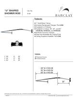
2.3.2 Field Communicator
An overview of the Field Communicator is shown in Figure 2-1.
See “Field Communicator menu trees” on page 125 for the menu tree diagrams.
Figure 2-1. 475 Field Communicator
A. Power key E. Enter key
B. Navigation keys F. Function key
C. Tab key G. Alphanumeric keypad
D. Backlight key
Get the latest Device Description (DD)
If the Rosemount 2140 DD is not included in your 475, then use the Easy Upgrade Utility to
update the Field Communicator with the latest DD.
For more information on how to update the DD and all the capabilities, see the 475 Field
Communicator User’s Manual
, available at www.fieldcommunicator.com.
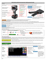
2.3.3 Local Operator Interface (LOI)
The LOI requires option code M4 to be ordered.
To activate the LOI, push either configuration button. Configuration buttons are located on
the LCD display (after removing the housing cover to access), or underneath the top tag of
the point level detector. See Table 2-1 for configuration button functionality and Figure 2-2
for configuration button location.
When using the LOI for configuration, several features require multiple screens for a
successful configuration. Data entered will be saved on a screen-by-screen basis; the LOI will
indicate this by flashing “SAVED” on the LCD display each time.
A
B
C
D
E
F
G

8
Reference Manual
00809-0100-4140, Rev AA
Configuration
January 2017
Configuration
LOI menu trees are available in Appendix D: Local Operator Interface.
Figure 2-2. LOI Configuration Buttons
A. Internal configuration buttons
B. External configuration buttons
Table 2-1. LOI Button Operation
2.4 Switching HART Revision
2.4.1 Switching HART revision with a generic menu
If the HART configuration tool is not capable of communicating with a HART Revision 7
device, it should load a generic menu with limited capability. The following procedures
allow for switching between HART Revision 7 and HART Revision 5 from a generic menu.
1. Locate “Message” field.
a. To change to HART Revision 5, enter HART5 and 27 spaces in the message field.
b. To change to HART Revision 7, Enter: HART7 and 27 spaces in the message field.
Button
Left No (SCROLL
Right Yes (ENTER
A
B

9
Reference Manual
00809-0100-4140, Rev AA
Configuration
January 2017
Configuration
2.4.2 Switching HART revision with Field Communicator
1. From the Home screen, select 2: Configure.
2. Select 2: Manual Setup > 5: HART (or 6: HART if Scaled Variable is available).
3. Select 2: Communication Settings > 4: Change HART Revision.
4. Change the HART revision.
Note
When messages about the loop appear, take appropriate safe action and select “OK”.
See “Configuration basics” on page 10 for further information.
2.4.3 Switching HART Revision with AMS Device Manager
1. Click on Manual Setup, and then select the HART tab.
2. Select Change HART Revision and then follow the on screen prompts.
Note
AMS Device Manager versions 10.5 or greater are compatible with HART Revision 7.
Note
When messages about the loop appear, take appropriate safe action and select “Next >”.
See “Configuration basics” on page 10 for further information.
2.4.4 Switching HART revision with Local Operator Interface
1. Press any LOI button to activate the menu.
(See Table 2-1 on page 8 for assistance with using the LOI buttons).
2. Scroll down (
) and then select EXTENDED MENU ().
3. Scroll down (
) and then select HART REV().
4. To change HART revision:
a. Select HART REV 5 () or scroll down (
) and select HART REV 7() to switch.
5. Exit the menu system by either waiting one minute for the EXIT MENU? prompt, or
scrolling down menus to find and select BACK TO MENU and EXIT MENU.
Note
When messages about the loop appear, take appropriate safe action and select “”.
See “Configuration basics” on page 10 for further information.
Fast keys
2, 2, 5 [or 6], 2, 4

10
Reference Manual
00809-0100-4140, Rev AA
Configuration
January 2017
Configuration
2.5 Configuration basics
The Rosemount 2140 and 2140:SIS Level Detectors (“level detectors”) can be configured
before or after installation. Configuring the point level detector before installation ensures
all level detector components are in working order before installation.
2.5.1 Setting the security switch
Verify that the security switch is set in the unlock position ( ) to proceed with
configuration. See Figure 2-6 on page 43 for the switch location.
2.5.2 Setting the loop to manual
When sending or requesting data that would disrupt the loop or change the point level
detector output, set the process application loop to manual control. The Field
Communicator, AMS Device Manager, or the LOI prompts you to set the loop to manual
when necessary. The prompt is only a reminder. Acknowledging this prompt does not set
the loop to manual. It is necessary to set the loop to manual control as a separate operation.
2.6 Configure device using Guided Setup
The options available in the Guided Setup wizard include all items required for basic
operation. All basic configuration parameters are described in “Basic setup” on page 14.
2.6.1 Guided setup on the AMS Device Manager
1. Click the Start button, and then select All Programs > AMS Device Manager >
AMS Device Manager.
2. Select View > Device Connection View.
3. In the Device Connection View, double-click the HART modem icon.
4. Double-click the device icon.
5. From the Home screen, select Configure > Guided Setup.
6. Select Basic Setup and follow the on-screen instructions.
2.6.2 Guided setup on the Field Communicator
1. Turn on the Field Communicator.
2. From the Main Menu, tap the HART symbol. The Field Communicator now
connects to the device.
3. From the Home screen, select Configure > Guided Setup.
4. Select Basic Setup and follow the on-screen instructions.
/